Week 4
Electronics Design
Objectives
Learnign Outcomes
Have I ...
Eagle
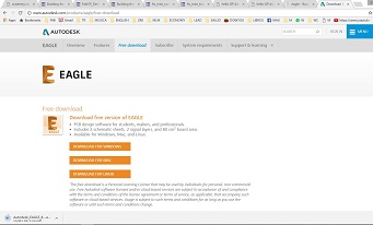
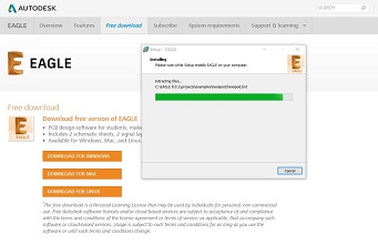
I decide to made my board based on Brian board. I download Eagle software from Autodesk and install on my laptop.
Design on Eagle
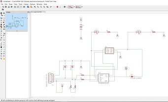
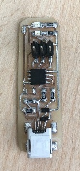
I design my FabISP using Attiny 45. In this case my board have mini usb because the suggestion was not use usb connector. There will be a short circuit damaging the usb port of your laptop or pc. I used the squematic from Brian page. About the board I made little changes.
I had one problem on Design phase, I couldn't find Attiny45 component on Eagle libraries. So I decide looking for this on internet. I did not find again. That is when I remember that in electronics production is possible to find a library.
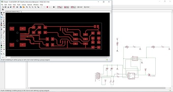
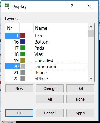
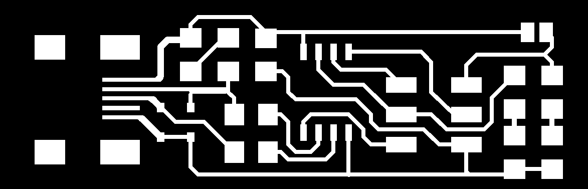
At the end of the design. To export an image .png. 1.Write "disp" and press enter on command toolbar 2.Choose only TOP and DIMENSION 3.Write "exp" and press enter 4.Choose the file where you want to save image .png 5.Mark Monochrome box 6.Number of pixels will be between 300 and 500 7.Check file where you save. It is done!

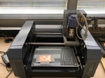
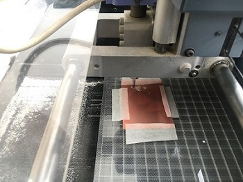
Manufacturing the PCB
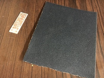
Take a new PCB and using a 3M doble tape (in this case was masking tape) put on the surface on Modela MDX-20.
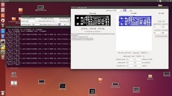
Now, open TERMINAL (I used fabmodules installed on Linux), write SUDO BASH, insert the password, write fab, press enter after each command.
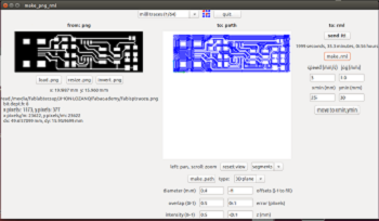
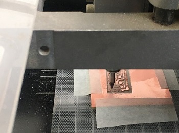
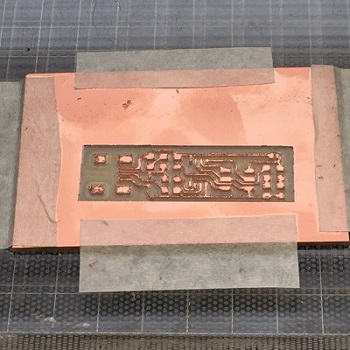
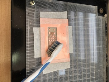
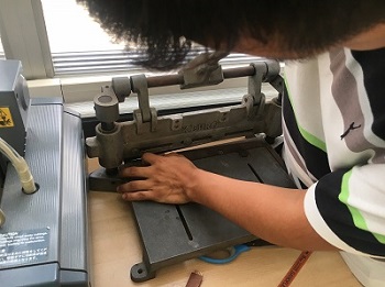
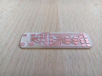
Follow those steps: 1.Choose "image.png" 2.Choose "Roland MDX-20 mill" 3.Click on "make_png_rml" 4.On the next window, click on "load.png" and choose your image 5.Make sure about the size indicated when you load your image 6.Set all parameters and click on "make.path", do not forget choose "mill traces (1/64)" at the top on the screen 7.Now, move modela header to the point where you want milling your board. Use a paper to calibrate distance among milling tool and board. 8.Click on "send it" 9.Inspect the board while milled 10.When the board was finished, using a brush to remove dust 11.In my case I cut PCB board waste using the guillotine 12.Using a sandpaper to give the final finishes
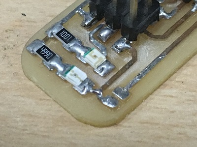
Soldering
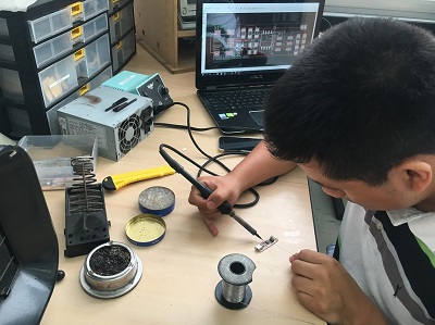
Once you have manufactured your PCB board, ask for electronic components to your instructor.
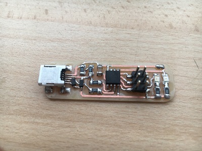
Follow those steps: -1x ATtiny45 -2x 1kΩ resistors -2x 499Ω resistors -2x 49Ω resistors -2x 3.3v zener diodes -1x red LED -1x green LED -1x 100nF capacitor -1x 2x3 pin header
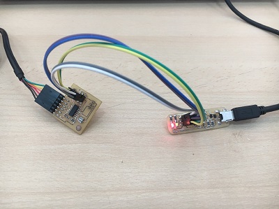
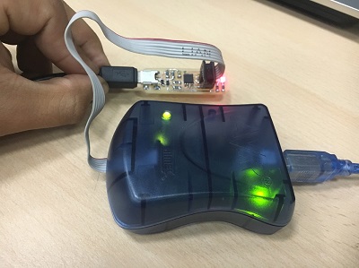
Get comfortable to solder the SMT components. Use tweezers, magnifiers, quick braid desoldering, etc. When you finish to solder, use AVR mkII to know if your PCB was well soldered (two green LEDs must be on).
Programming
I programming my FabISP on ubuntu. Use the next command line to update software.
sudo apt install avrdude gcc-avr avr-libc make
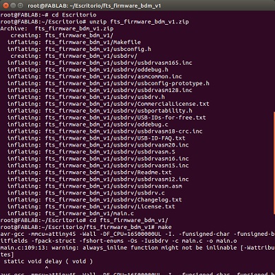
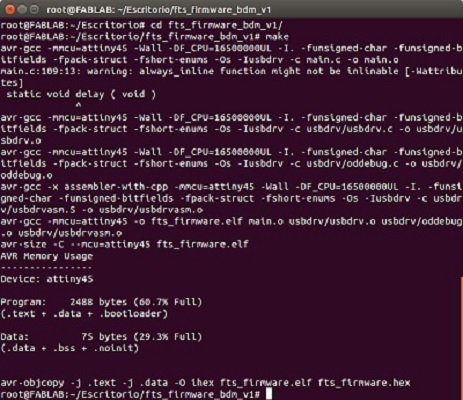
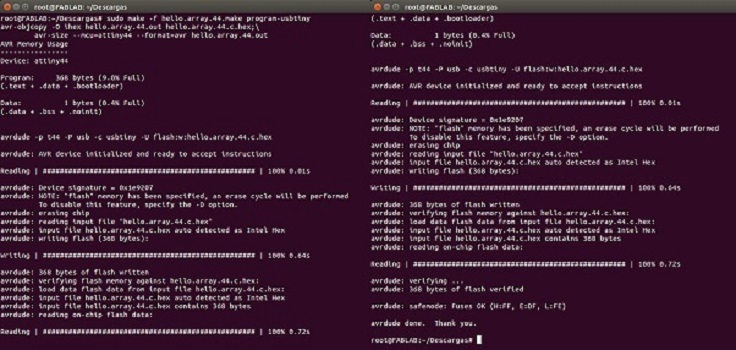
Now, download the firmware source code. and extract the zip file "unzip fts_firmware_bdm_v1.zip". Open your terminal program and cd into the source code directory. Run "make", the file .exe will be build. When the command completes you should have a file called "fts_firmware.exe". In my case I used a programmer with an Attiny so I did not have to change my .exe file. Now connect the programmer and the usb port using a cable.
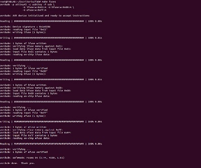
Run "make flash". If something went wrong, look for shorts using multitester, check your soldering, check connection between USB ports or change usb cable and programmer connection. Then "make fuses", if this step fails but the previous one worked, you likely have an intermittent connection somewhere.
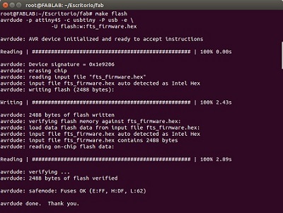
Run "make fuses", if this step fails but the previous one worked, you likely have an intermittent connection somewhere.
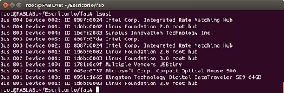
Disconnect the programmer from the card, olny keep usb connection. Run "lsusb", there must appear your board as "Multiple Vendors USBtiny", if not check the mini USB soldering. Connect your ISP programmer to your board one more time, and run "make rstdisbl".
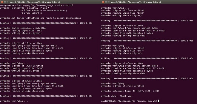
We need to disconnect VCC from the Vprog pin on the ISP header by removing the bridge on the solder jumper.
Files
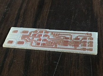
Here my files: -JhonISP traces (.png)
Result
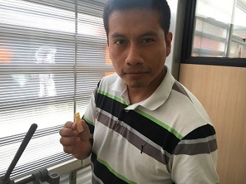
JhonIsp is done! It is working!
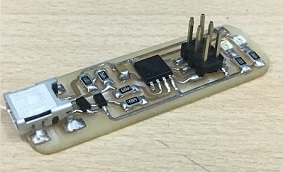
JhonISP