The assignment
This week’s assignment was to, in group, make a machine, including the end effector, build the passive parts and operate it manually.
The Light Painting Machine
I worked in group of 3, myself, Ola and Birkir. See group documentation here.
My main contributions
My main contributions during this week were:
- building the linear stages from Nadya’s modular design;
- finding a solution for attaching the end effector;
- testing long exposure picture set up and settings.
Building the linear stages
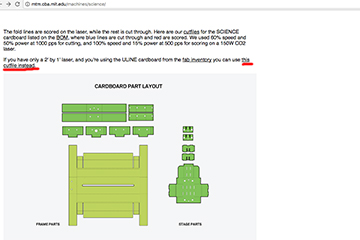
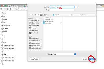
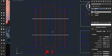
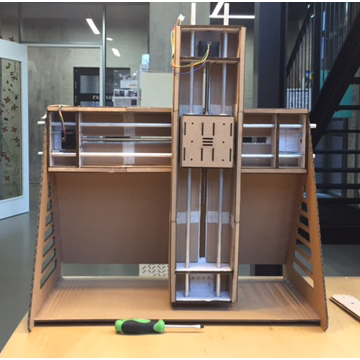
The light painting machine is based in 2 stages. To build them, I went to Nadya’s and James’ documentation. Their standard files required a bigger laser cutting area, so I used the file for ULINE cardboard. To save the file, you need to right click and “save as”, changing the file extesion to .dxf (instead of .txt).
Then I opened the file in AutoCad and made sure the settings (line thickness and color) were suitable for our laser cutter.
The cardboard we had in the lab is 3.1mm, instead of 3.85mm, but it worked very fine. To make it easy to assemble, I downloaded the GIF animation from the webpage, and played it picture by picture.
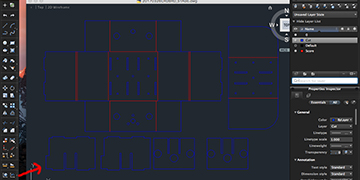
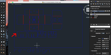
The outer envelope of the stages was missing holes (at least on one side, for the aluminium rods to slide in), but we did them manually with a drill machine, using the inner holes as reference. We checked and the standard dxf file was correct, so the holes were only missing in the ULINE file. The central box also showed problems in the ULINE file, namely with the placement of the holes for the aluminium rods. So for the central box, we lasercutted from the standard file instead of the ULINE.
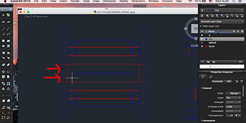
When attaching the nut from the lead screw to the central box in the stages, we become aware of an error with the cut files. I fixed it in Autocad, lasercutted the new file and everything worked perfectly.
Also, in the beginning we had some troubles sliding in the lid of the central box, it was too tight… But the problem was solved by “massaging” the edges cardboard.
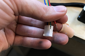
During the assembling, when everything was already glued and dry, the plastic cap where the cables from the motor come together broke. Instead of exchanging the whole motor (by that ruining the cardboard envelope), we managed to click out the remaining cables and set them in a new plastic cap (that we took from a spare motor).

The end effector
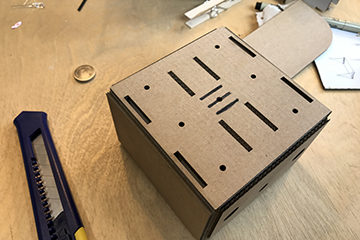
The end effector for this machine would be some sort of light. My goal was just to create a fast solution that would still around a certain degree of freedom to play with colours, amount of LEDs, etc. So I started by using a knife and manually cutting 3 rectangles in the central box, where a 3V batteries could fit. Like this, we could attach 1, 2 or 3 LEDs, as well as easily change them around.
Testing long exposure picture set up and settings
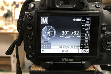
After our machine was done and tested its operation manually, I set up a tripod and a camera in a dark(er) room and made a couple of long exposure pictures, once again moving both x and y axis manually.

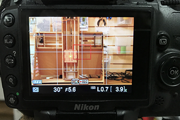
On the first, test, only 1 red LED was on, aperture was set on a factor of 5.6 and shuttle speed on 30 seconds. The result was quite good for a first experiment.

On the second trial, we had 3 LEDs (red, white and blue) and the same settings. The result was bad! The LEDS transmitted too much light, so it wasn’t possible to recognise the line “painted” by the LEDs.
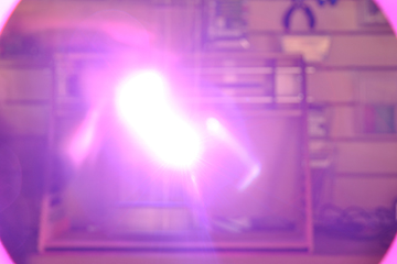
I the changed the aperture to be narrower, to a factor of 32 (max), and kept the shuttle speed on 30 seconds. It worked much better. The line is thicker than in the first experiment, where there was only 1 LED (instead of 3), but that was also expected.

In the coming weeks, we want to work more with the end effector. We are considering to have a circuit board, with multiple LEDs, and have a micro controller commanding which LEDs to turn on, as well as their blinking intervals.
A little extra… problems with GIT
There was some problems with GIT this week, something with access rights… To solve it, it’s necessary to remove the existing known_hosts. I’m using Terminal on a MacBook. To solve it, I…
- opened Terminal;
- typed ssh-keygen -f “.ssh/known_hosts” -R “git.fabacademy.org”;
- then went into the directory where I have my local repo (cd fabacademy2017, cd fablabspinderihallerne);
- typed git pull;
- a yes/no question showed, basically asking if I would like to accept the new host settings; I typed yes;
Everything works now, but git pull and git push became extreeeeeeemely slow commands.
