The assignment
This week’s assignment was to make something BIG on a CNC milling machine.
Designing for machining
So, since I’ll be producing some kind of wearable as a final project, I decided to make a mannequin. That involved some 2D files (making the stand) and 3d files (the mannequin body form itself).
I made the stand’s 2d files using Fusion 360. I used parameters, here is a really good tutorial, explaining how to take most advantage of parameters, so that if your design changes, you only need to update in one place. This proved to be specially helpful when testing joints later on.
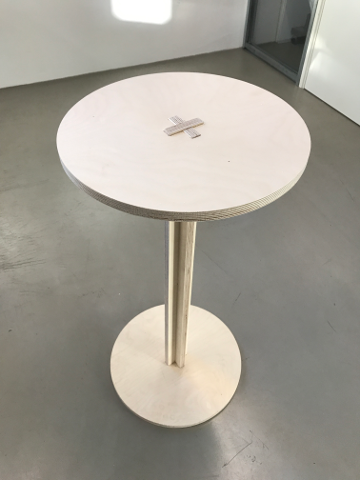
The stand is made of 18mm thick plywood and consists of:
- a bottom;
- a leg, consisting of 2 rectangles built together through a long finger joint; the leg builds up to the right height of the bust;
- a top, where the foam bust will rest.
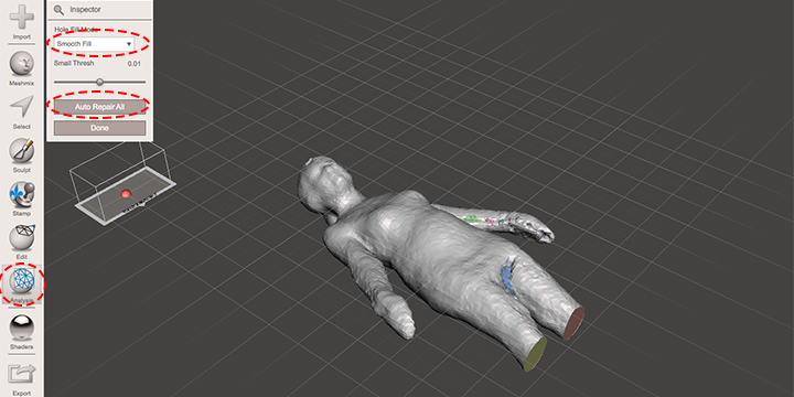
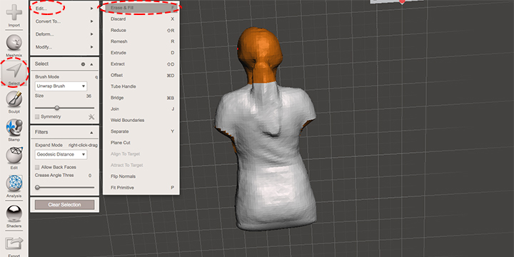
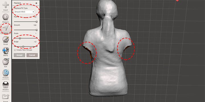
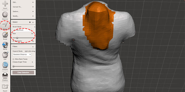
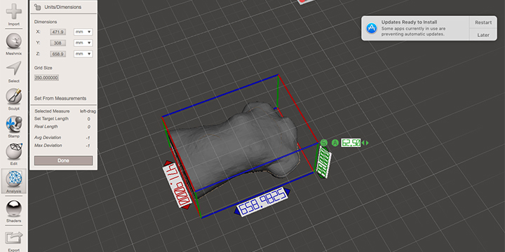
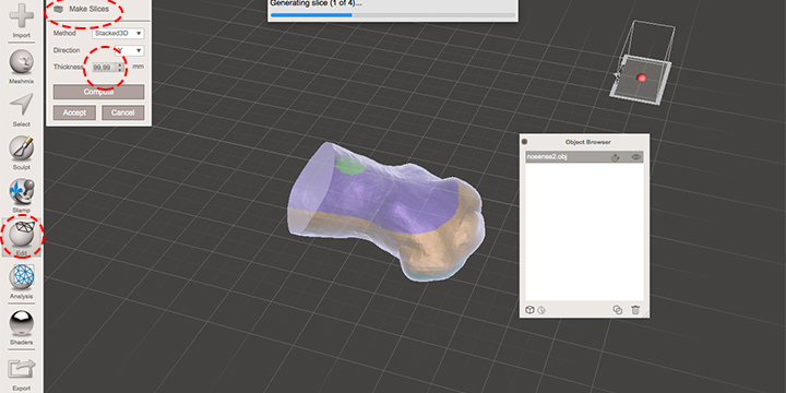
For the mannequin itself, I asked a colleague to 3d scan me. I used the iSense 3d scanner, that I have used previously in week 5 (link). Then, I imported the model in Meshmixer. Meshmixer has very good analysis tools to repair the mesh and work out the model (cut out arms, legs and head, correct ponytail, analyse and repair mesh, slice in material thickness - 10cm, etc.).
I saved the files in formats that were compatible with VCarve, so that I could generate tool paths for machining. So the 2d files from Fusion I exported as DXF and the 3d files from Meshmixer as OBJ. You can download all files in the end of this page.
Creating the toolpaths
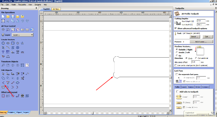
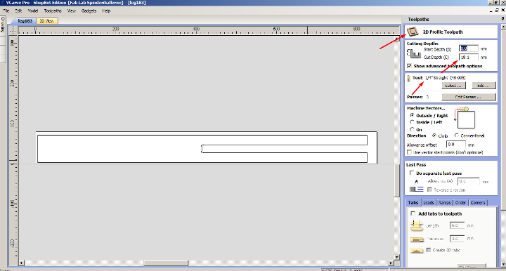
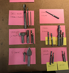
I started by creating the toolpath for the stand. I decided to use the 1/4 inch, 1 flute, straight milling bit; after my instructor’s explanation, it seemed a good compromise between an ok finishing look and milling speed. If the finishing look was the only focus, I would have started with a downcut milling bit, up to 11 mm depth, and a upcut milling bit afterwards, from 9-20mm depth (material is around 18mm thick).
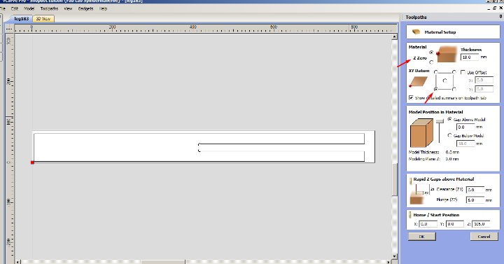
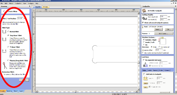
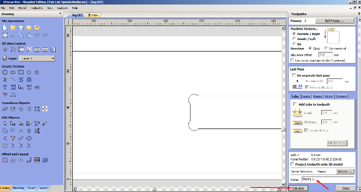
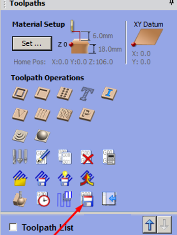
So I opened the DXF files in VCarve, one at a time, and set up material dimensions, the zero, the corners, the milling mode, the tool (milling bit) and tabs.
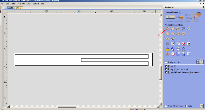
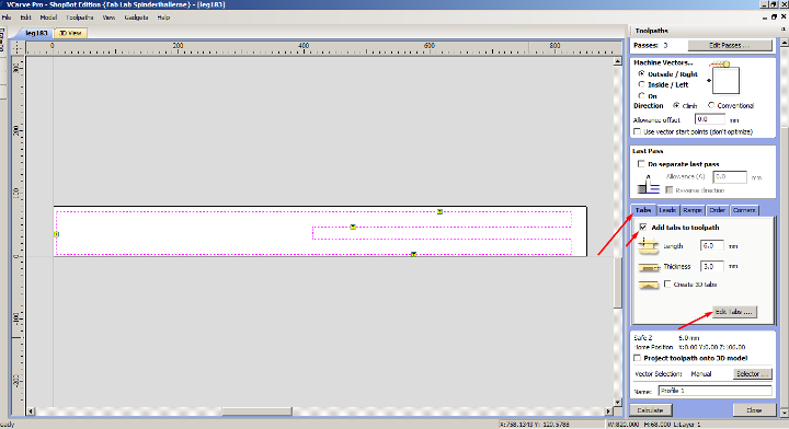
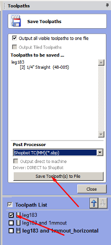
I then generated the toolpath and save it as a SBP file for the Shopbot (the brand of our large milling machine). After generating the toolpath and before saving, you are able to run a preview of the toolpath(s) generated.
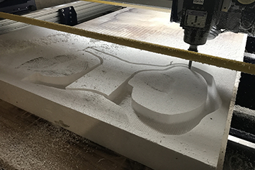
I proceeded by creating a toolpath for the foam. In Meshmixer, I have divided the mannequin in 10cm thick parts, which resulted in 3 slices (actually 4, but the forth slice was only 1,5cm high and corresponded to the belly area; I’m currently pregnant, so I thought there was no need to machine that part, since it will grow anyway). I decided to use a 1/2 inch, 2 flutes, spiral ball nose milling bit. It was important that this was long enough to mill 10cm thick foam; foam is a relatively soft material, so I could push the milling bit grip area to the limit.
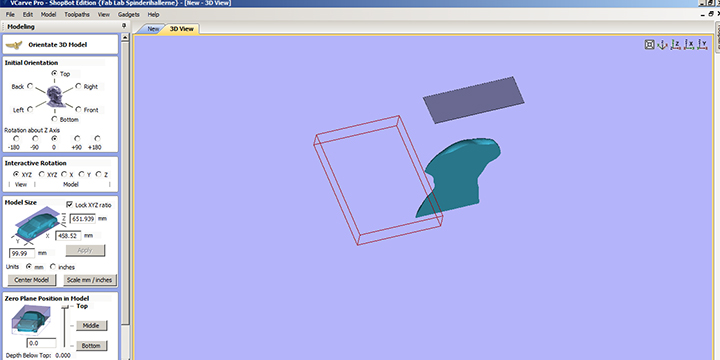
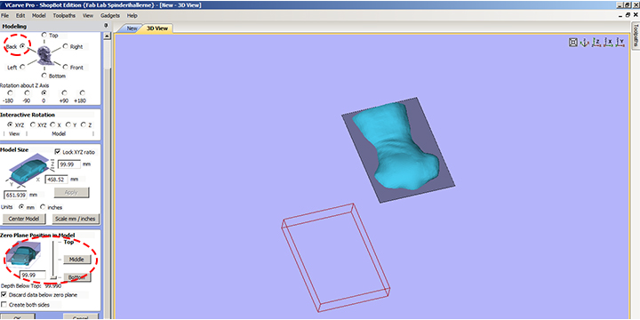
I started by creating a new file, setting up material dimensions, zero and then importing the first slice of the mannequin as an OBJ file. Then I rotated and adjusted the 3d model to the cutting area.
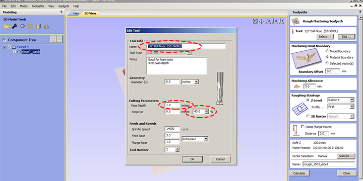
It was the first time cutting foam in our machine, so I decided to create new tool, as a reference for future users. In the tool section, I created a new folder called Foam. Then adjusted the cutting parameters, Feeds and Speed for the 1/2 inch Ball Nose tool. Comparing to the same tool being used for wood, on foam I changed…
- … the pass depth to a higher value, 1.4 inch;
- … the stepover to a higher distance value, 0.2 inch;
- … the spindle speed to a higher value, 140.000 rpm;
- … the feed rate to a higher value, 3 in/s.
Regarding milling modes, I used 3d roughing and 3d finishing for each slice. On the 3D roughing mode, I had a machining allowance of 5mm, in order to leave some material to be machined in the 3D finishing mode.
Once more, I generated the toolpath and save it as a SBP file for the Shopbot - this time the file consisted of 2 toolpaths that would run one after another. In this case, it was specially helpful to run the preview video. I had a couple of mistakes in the first toolpaths generated… Running the preview video helped to improve the toolpath and avoid running into trouble and wasting material and time later on, during machining. I applied the same procedure for the other 2 parts of the mannequin that needed to be machined in foam.
Machining
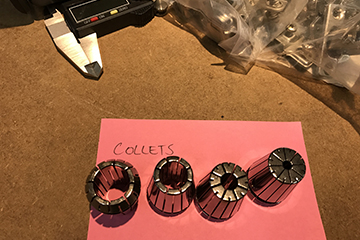
In December 2016, together with Bas Withagen, I installed the large CNC milling machine in our lab. At that time, I had training with Bas about the different milling bits, techniques and procedures. Even before designing for machining, I started by taking Ola (my fellow student) through the same training. When we had need for deeper knowledge, we easily found answers on the web. Here is a good article about general stuff to consider when using a CNC milling machine.
I started by milling the stand. For that I loaded a 18mm piece of plywood on top of our large milling machine sacrificial layer. I then loaded the 1/4 straight 1 flute milling bit. I fixed the plywood with screws only on the edges. I zeroed the machine on the X and Y axis, with a good distance from the screws and then used the zero plate to zero the Z axis (on the top of the material).
I saved all SBP files from the usb in the desktop of the computer connected to the Shopbot and removed the USB to prevent any interference.
I loaded the SBP file for the leg and followed the instructions on the screen. VERY IMPORTANT!!! READ CAREFULLY INSTRUCTIONS GIVEN BY THE PROGRAM, NAMELY THE PART WHERE YOU START THE SPINDLE, BEFORE ACTIVATING THE TOOLPATH!
After starting the spindle and hearing it was functioning, I then turned on the exhaust system. Only after, I activated the toolpath. I kept my eyes on the spindle, while having my fingers close to the space key. (in case of a problem or an error, this would be a way of stopping the machine without losing position). The emergency button was right next to my hand as well.
When it was done, I turned off the machine and took a closer look. Everything seemed fine. I then repeated the process for the other part of the leg, the bottom and the top of the stand. I used a hammer and a chissel to remove the tabs and unloaded the parts.
I then removed the screws and the 18mm piece of plywood.
I attached the first foam piece to the sacrificial layer with double sided tape. While trying to move around the spindle head and zero the axis, I ran into a lot of problems… the spindle head kept on dropping for no apparent reason… Even when I managed to zero the axis and start running the toolpath, it would stop around line 20. By talking to my instructor, we had a suspicion that it had something to do with the max. height for the Z axis. We talked about 2 possible solutions:
- change Z zero to bottom of material to avoid safe rest position being higher then max. height for Z axis;
- look into the machine setup file and change the safe rest position to a lower value. Shopbot tutorial here.
The problem was solved by going back to VCarve and changing the zero to the bottom of the material, as well as carefully measuring the length of the milling bit that was exposed (10.5cm).
Then everything ran smooth. I repeated the process for the other 2 slices of the mannequin.
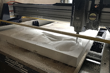
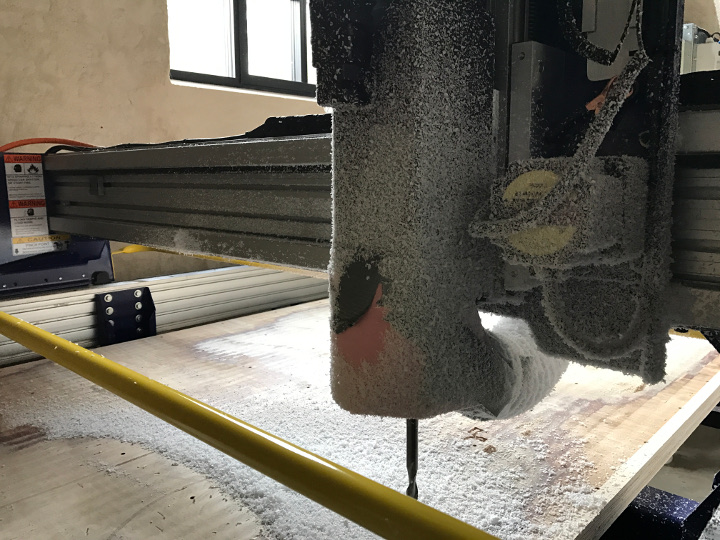
NOTE: foam is messy!! Specially a thick piece, because it prevents the exhaust to be more efficient - milling bit keeps the distance between the material and the exhaust tube. I made a fast solution in carton, trying to get the exhaust to be more efficient, but it was still a lot of work to clean everything after the finished…

Assembling
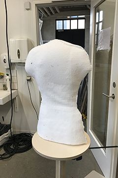
When all files were machined, I assembled them.
For the wood, I verified that the long finger joint was not the best choice. I had to hammer it hard both in the bottom and top parts. Next time I’ll do a leg that is t-shaped instead, machining two simple rectangles. It is easier to be precise and work with tolerances that way.
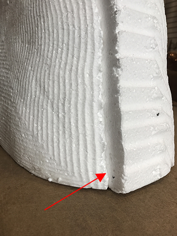
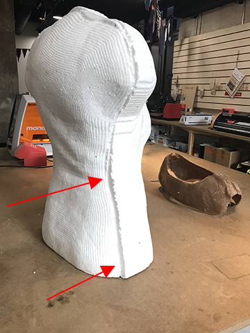
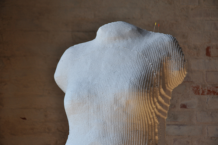
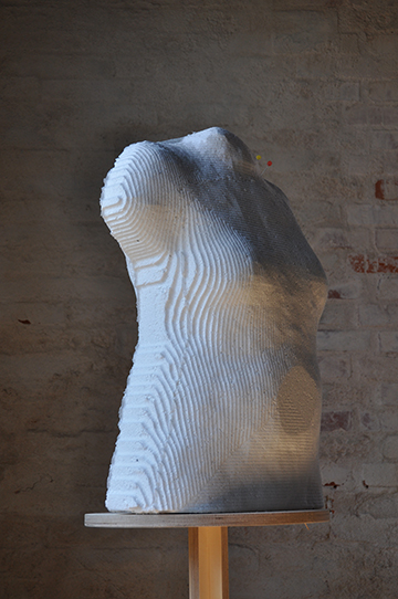
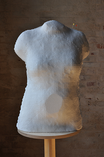
About the 3d milling, only in the assemble phase I realised that it should have been double sided (slice 2). It was a very small part that it wasn’t able to mill, so have decided to fix it using a hot wire (hand sculpt). I assembled the 3 foam slices with white glue and voilà!:D
Main learnings from this week
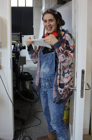
The large milling machine is the most powerful machine in the lab, it demands high respect and focus when operating it. It’s really important to follow all regulation in the room, and always wear eye protection when around this machine.
Working with foam is messy, the thicker the block, the bigger the compromise with extraction efficiency. If I should do something similar in the future, I would probably use 5cm thick foam instead.
Foam might be annoying when it comes to dust, but it proved to be a cheap and fast way of testing 3d roughing and finishing tool paths.
Working towards the final project
I was quite happy with the end result of this week. Making a personal mannequin in foam was cheap, easy and fast to mill. Foam seems ok durable and great to use together with sewing pins when working on final project.
Files
All files can be found here. To download the files, right click with the mouse and chose “save link as”.
Foam_OBJ_part1, Foam_OBJ_part2, Foam_OBJ_part3, Foam_OBJ_part4
Foam_VCarve_part1, Foam_VCarve_part2, Foam_VCarve_part3
Foam_Shopbot_part1, Foam_Shopbot_part2, Foam_Shopbot_part3
Stand_Leg_VCarve, Stand_Base_VCarve
