Final Project Development & Process
Project Timeline
Development Summary
I am thankful for my department and colleagues for their understanding that I am able to meet my weekly development on time. Therefore most of task met its deadline. The only tasks to complete are to finish up the reports and waiting for next phase of timing to improve the machine.
9 to 15 Apr 2017 - Soldering of Fabkit 0.4
17 to 22 Apr 2017 - Designing of breakout boards
24 to 29 Apr - Testing out the Fabit with Arduino IDE Codes
1 to 6 May - Planning and designing of 2D and 3D designs of vacuum former.
7 to 13 May - Fabricating partial 2D designs of the Vacuum Former, making test cut
14 to 20 May - Fabricating 2D designs on plywood
21 to 27 May - Design and fabricating 3D design for Vacuum Former
29 to Present - Assemble of Vacuum former and Spiral improvement to the Vacuum Former.
15 Apr 2017 - Soldering of Fabkit 0.4
Task: Soldering of the Fabkit was a big challenge to me. After soldering, I bootloaded the Fabkit with the instructions and did uploaded the Blink Example code and it works! Super delighted!
22 Apr 2017 - designing of breakout boards
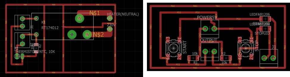
Task: Designing 2 breakout boards, thermistor and button boards
29 Apr - Testing out the Fabkit with Arduino IDE Codes
Task:Testing out with some basic codes and figuring out the IO pins. Reading the datasheet
6 May - Planning and designing of 2D and 3D designs of vacuum former.
Task: Looking at reference pictures of other compact Vacuum formers and gathering ideas on how to make it.
Watching YouTube videos on how people use vacuum formers.
13 May - Fabricating partial 2D designs of the Vacuum Former, making test cut
Task: Using the laser cutter and paper, I cut out the rough design of the vacuum former and test fit it.
20 May - Fabricating 2D designs on plywood
I decided to use plywood as I have no access to metal sheet nor I have prior knowledge to it.
27 May - Design and fabricating 3D design for Vacuum Former
Task: Design it on Fusion 360 and made some test prints for the project.
29 May to present - Assembly, testing and fabrication of Vacuum Former (and Spiral Improvements!)
Task:
After working on my Input devices, I decided to work on my programming part for my Fabkit.
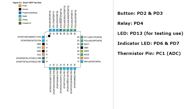
1) Using the thermistor as in input
2) Display temperature to I2C
3) When the temperature reaches a certain temperature, it will trigger the relay to turn off the heater
4) Relay to maintain till condition is met to turn on the machine.
I will be designing the body of the Vacuum Former with Plywood. As the Fablab in library there is no Metal work and I have no experience in using the proper metal. Therefore, I decided to work on Plywood.
Development & Process
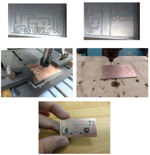
Fabkit 0.4
Made some tweaking, modification and soldered the board. Bootloaded it and ran some basic codes to test its functionality. Great success!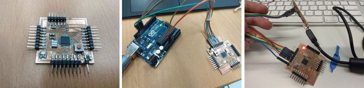
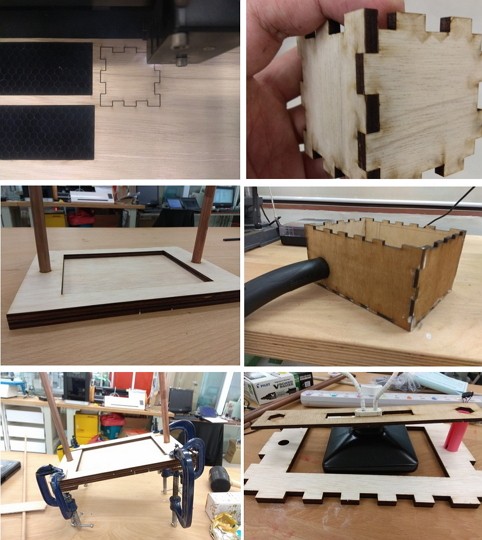
Prototyping
First, I Designed it on paper on how it would look like and the size of the Vacuum Former. Then I used the Laser cutter to cut out a prototype with the finger joins to see how it would look like.
Testing of boards and integration
Testing of boards in breadboard first and then design, mill and integrate.
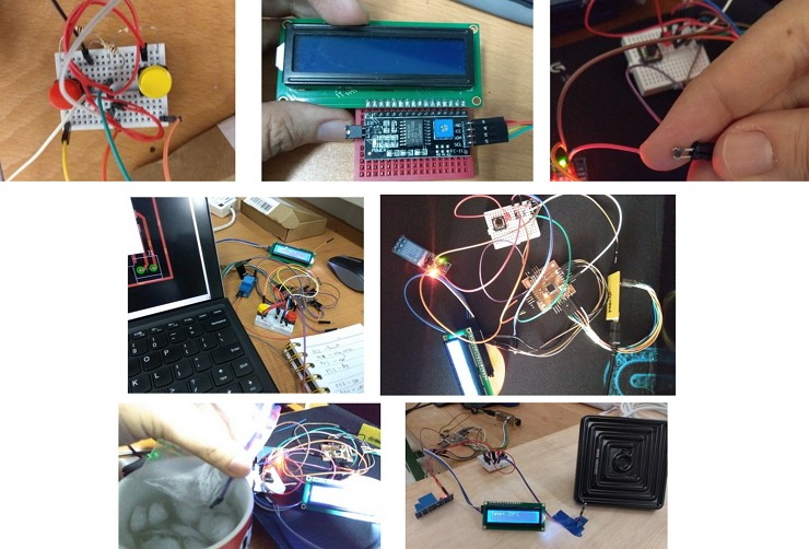
Circuit Fabrication
After testing, I designed 2 breakout boards, one as button input and the other to control the relay to turn on the heater.
Computer Controlled Fabrication
I decided to use Laser Cutter for my project body as I mentioned, I am not familar with metalwork.
Therefore I used 10mm and 5mm plywood to create my vacuum former body.
I also used glue to stick pieces of wood together to make the base thicker.
3D Printing
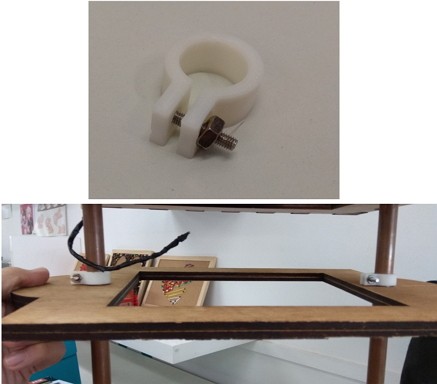
I had to design 3D models to hold my copper rods as there is no base to hold it, therefore I designed in to hold M6 Nut and Bolt so that it can screw into place when installation.
I also designed a c-clip to restrict the plastic holder to a certain distance away from the ceramic heater.
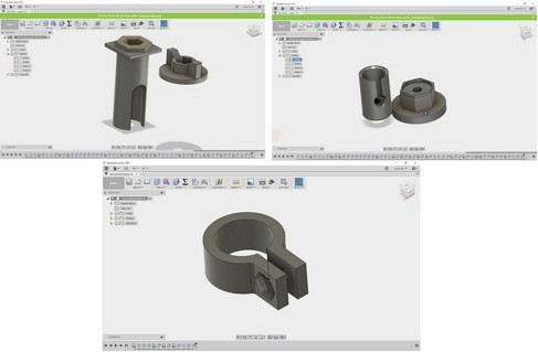
Base: using M6 Nut and Bolt
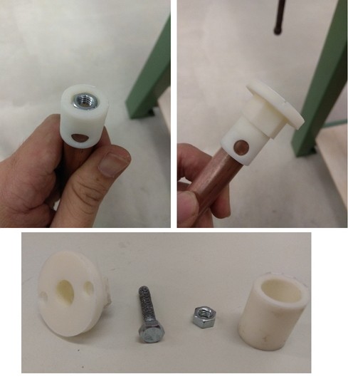
Top: Using M6 Nut and Bolt
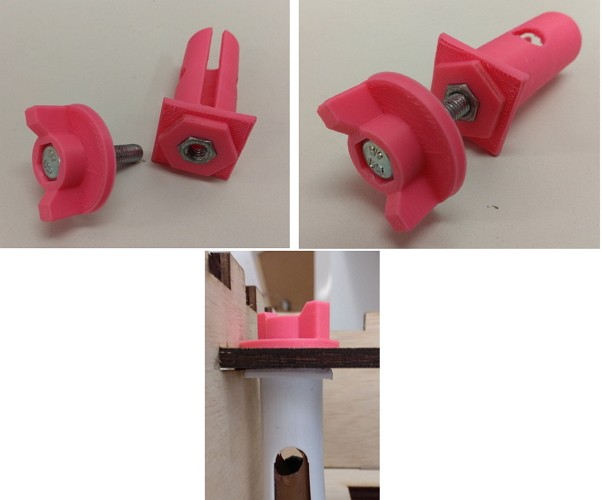
C-Clip: using M3 Nut and Bolt
Final assembly, testing & improvement
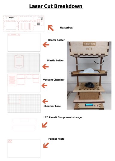
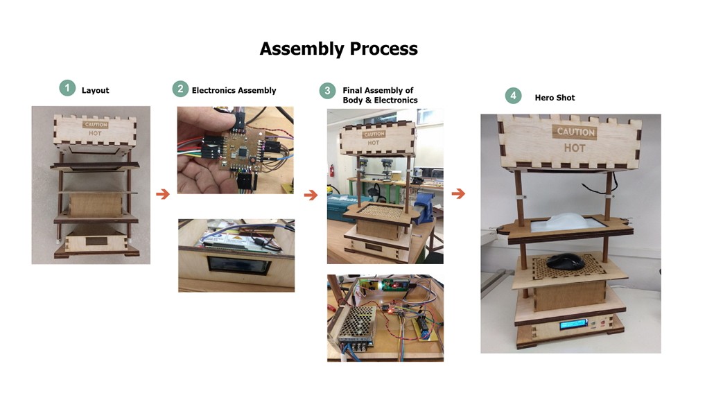
This is the breakdown of what have I done for the body of the vacuum former, I used Corel Draw and Adobe Illustrator to create the drawings of the box and laser cut it using Universal Laser System.
I also did some engraving for the wordings like Fablab & Caution Sign
After Laser cutting and gluing some parts, I decided to do a test assembly to see if it is working.
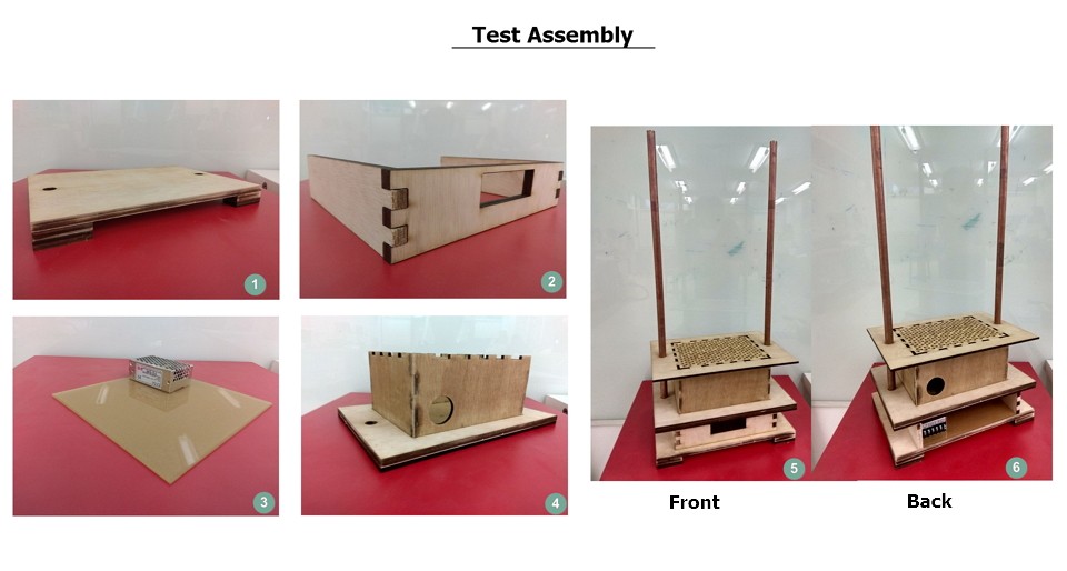
After double checking of the components and electronics, I assembly the whole machine.
During this phase, I had some challenges, like how do I hide the wires in the copper tube, how do I make it more visually interesting and how to make it more stable. Like what Neil has mention Spiral improvments.
After setting up the vacuum former, I realised that the thermistor is reading the heat radiated from the heater to the surface of the plastic instead. I was lucky to have a FLIR themometer from my dad and I checked the differences, it is approximately 50-60 degrees difference. It is to compensate the measurement of ambient temperature from the Thermistor and on the surface of the plastic.
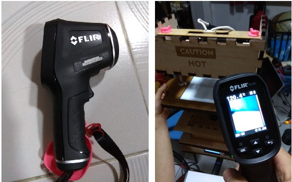
This method may not be the best practice, but based on experimentation, the compensated measurement from the Arduino/Thermistor reading is about the sameas the reading by the FLIR.
Testing
I didnt manage to get HIPS (High Impact PolyStrene) but instead, I got Strene from our local Art Store.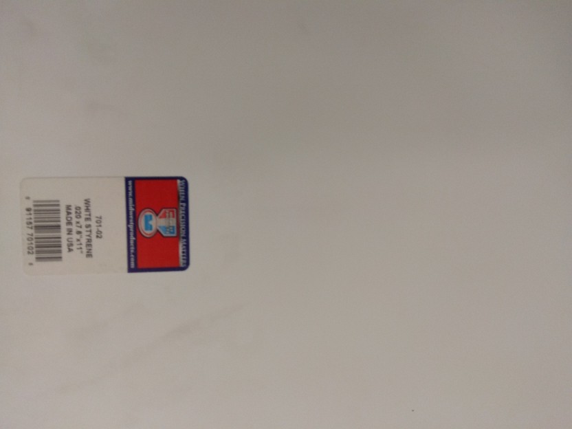
Dimension: 7.6in x 11.0 inch x 0.20 inch (193mm x 279.4mm x 0.5mm) Cost: 3 SGD , ~2.17 USD
I read online regarding the MSDS: here and MSDS sent by Midwest themselves here
I set my Arduino IDE code to read the surface temperature to about 150 degrees and then toggle the relay to turn it off to retain the heat. With that it can be safe that the temperature will not over heat the plastic.
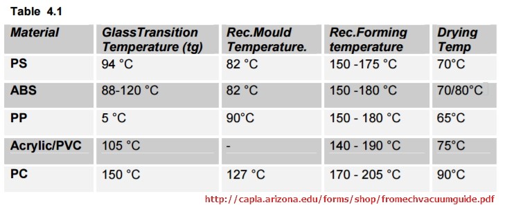
In the future if I want to use other material, I'll use this chart as a reference in the future.
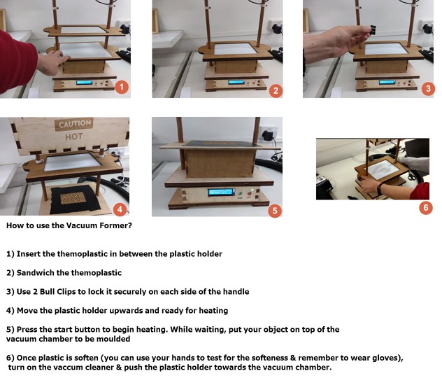
Here is the pictorial guide on how to use the vacuum former:
Results?
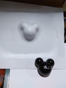
My first test was using a Mickey shaped cover that I found it at home.
I pressed on the start to let it heat and moved my plastic holder towards the ceramic heater
When it reaches 150 Degrees (as stated on MSDS, 150 - 175 degrees is optimum) on the surface, the Relay kicks in to stop supplying power to the heater and it retains the heat.
Once it became visually soft, I followed how the Youtube videos has been testing visually, they use the probing test to see if it is soft enough to mould.
Then I turn on my Vacuum Cleaner and I pressed it down to the Vacuum chamber.
And walla! It Works!
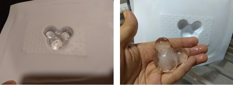
As Styrene is used in packaging, I also decided to do some 'casting' with water and to make it into Ice cube!
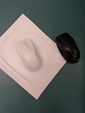
Testing didnt stop there! I tested on moulding a wireless mouse as a packaging example. And here is the result:
Improvements
These are some improvements along the way, like what Neil has said, Spiral Improvements.
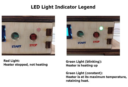
Improvement 1: I added LED indicator lights, to show the users when the heater reaches its recommended heat.- Blinking Green Light: Ceramic heater is heating up to the temperature
- Constant Green Light: temperature limit reached, controlled by code.
- Constant Red Light: Heater has stopped and is cooling down
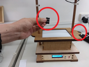
Improvement 2: - Additional Bullclips to hold the plastic firmly while heating to prevent warping.
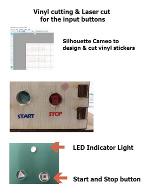
Improvement 3: - Added 2 buttons to indicate start and stop - Added 2 vinyl cut stickers to indicate start and stop of the button
Improvement 4: - Adding tape to seal partial holes of the Vacuum Chamber to reduce vacuum leakage from the sides.
Improvement in the future: - I may include a buzzer or tone to indicate that the heater is at it's peak.
- I may shorten the distance of the copper rod, so that the distance to form required is lesser so as to prevent it from cooling too fast when pushing it down to form.
- I may change to a bigger heater to even out the heating of the plastic.
- I may use a switch to turn on the vacuum cleaner upon pushing down to the chamber. - Increase copper pipe size
Failures and Findings
After working and doing testing on the vacuum former, I realised and learnt many new things!Failures:
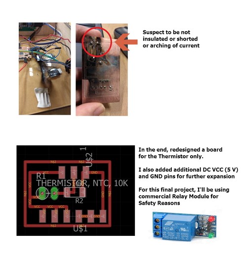
1) While working on the relay board and testing it, my board got shorted and destroyed it entirely. With the fear of safety, I seeked adviced from my dad and learned that my board may not be well insulated and may be connected wrongly. Therefore I created a new board for my thermistor and using a Commercial board for the relay.
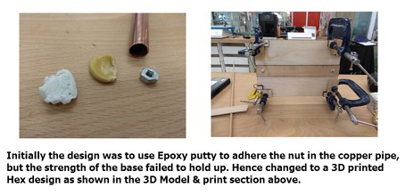
2) When working on the body for the Vacuum former, I had a hard time trying to make the base stable as it is a copper pipe and there was no way to stablize it. My course mate, Jeff, adviced me to design a hex design to affix it to the base to stable it. There is where I 3D design it and placed it on the base.
3) My Guru, Steven Chew, told me that it is critical to have a even heat on the surface of the plastic. My ceramic heater is small and therefore may not achieve even heating, to fix this, either I make it smaller or change the heater size.
Findings:
1) While testing the vacuum former, like I mention, I realised that the thermistor only measures the radiated heat and not the surface. Therefore I had to recalcuate and made compensation.
2) The plastics will tend to warp when heated due to uneven heating, to fix this, I added 2 bull clips to sandwich it firmly.
3) Not all vacuum cleaners come with the same hose size, I may need to design an adapter for other vacuum cleaners.
References
Styrene.org: link Styrene MSDS :linkThermoforming by Plasticsmag :link
Toolcraft Plastics: link
Fabkit 0.4: link
Thermistor on Arduino: link
Formbox: link
Downloads
Lasercut plans for the Vacuum Former Body: zip3D print holder for the Copper Pipes: zip
Arduino INO code: here
Eagle sch & Brd:Fabkit(fixed), thermistor, button