Exercise 15 -Networking & Communication
I2C
This week we are to make something that has Network & Communication. Thus I've decided to make I2C as my Final project will have an LCD which I decided to have and LCD indicator, and to also make a better understanding of how it work.
What is I2C and how it works?
"It is a serial Protocol for 2-wire interface to connect low-speed devices like microcontrollers, EEPROMS, A/D and D/A converters, I/O interfaces and other similar peripherals" source
In short, it is using a Master board to control the slave board via 2 lines, SDA and SCL.
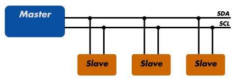
"SCL is for the clock signal, and the SDA is for the data signal. Both the SCL and SDA lines are "open drain" drivers. What this means is that the chip can drive its output low, but cannot drive it high. For the line to be able to go high you must provide pull-up resistors to the 5V supply. You only need one set of pull-up resistors for the whole I2C bus and not for each device. If the resistor are missing, the SCL and SDA lines will always be low - nearly 0 volts - and the I2C bus will not work." source
The I2C bus is a half-duplex, synchronous, multi-master bus requiring only two signal wires: data (SDA) and clock (SCL). These lines are pulled high via pull-up resistors and controlled by the hardware via open-drain drivers, giving a wired-AND interface. I2C uses an addressable communications protocol that allows the master to communicate with individual slaves using a 7-bit or 10-bit address. During communication with slave devices, the master generates all clock signals for both communication to and from the slave.
Each communication begins with the master generating a start condition, an 8-bit data word, an acknowledge bit, followed by a stop condition or a repeated start. Each data bit transition takes place while SCL is low, except for the start and stop conditions.
The start condition is a high-to-low transition of the SDA line while the SCL line is high. A stop condition is a low-to-high transition of the SDA line while the SCL line is high. The acknowledge bit is generated by the receiver of the message by pulling the SDA line low while the master releases the line and allows it to float high. If the master reads the acknowledge bit as high, it should consider the last communication word not received and take appropriate action, including possibly resending the data.
Board Designing
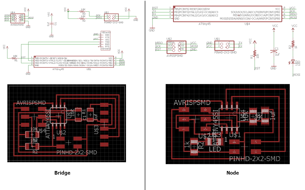
But before I jump in into the LCD module for my final project, I designed the I2C Bridge and Node done by Neil and to create it, I'll use Eagle again to redesign the board.
After designing, mill and solder we are coding it in Arduino IDE.
In order for ATtiny MCU to communicate using I2C, new libraries need to be install into Arduino IDE. As a Master ->TinyWireM, as a Slave ->TinyWireS.
To include library in Arduino IDE. TinyWireM.h as master and TinyWireS.h as slave
    #include "TinyWireM.h"
    #include "TinyWireS.h"
In I2C, to initialize as Master address is not require. But as a Slave user need to predefine an address for the MCU
Using the command "begin" for initializing the MCU
    TinyWireM.begin();

    -------------------------------
    #define I2C_SLAVE_ADDRESS 0x6

    TinyWireS.begin(I2C_SLAVE_ADDRESS); // join i2c network as slave
Example are included when both the library are install, or more example can be found on the web site (TinyWireM, TinyWireS).
Master
		#include <TinyWireM.h>
		#define slave1 (1)
		#define slave2 (2)
		void setup() {
		TinyWireM.begin();
		}
		void loop() {
		TinyWireM.beginTransmission(slave1);
		TinyWireM.send(1);
		TinyWireM.endTransmission();
		delay(2000);
		TinyWireM.beginTransmission(slave1);
		TinyWireM.send(0);
		TinyWireM.endTransmission();
		delay(2000);
		TinyWireM.beginTransmission(slave2);
		TinyWireM.send(1);
		TinyWireM.endTransmission();
		delay(2000);
		TinyWireM.beginTransmission(slave2);
		TinyWireM.send(0);
		TinyWireM.endTransmission();
		delay(2000);

		}
What does the Master code mean?
First, the library TinyWireM is included, next is to define the 2 slaves that I would be using.
Next, we will begin the TinyWireM library, and then it will parse into the Loop
In the loop, it will 'transmit' a signal, 1, to the 'slave1' and it will end the transmission and delay for 2 seconds. Then it will 'transmit' a signal, 0, to the 'slave1' again and it will end the transmission and delay for 2 seconds.
After "slave1" is done, "slave2" will be called in action, and back to "slave1".
Slave1
		#include <TinyWireS.h>
		#define output (PB0)
		#define I2C_SLAVE_ADDR (1)
		void setup() {
		// put your setup code here, to run once:
		TinyWireS.begin(I2C_SLAVE_ADDR);
		pinMode(output, OUTPUT);
		}
		volatile byte msg = 0;
		void loop() {
		if (TinyWireS.available())
		msg = TinyWireS.receive();
		if (msg == 1)
		digitalWrite(output, HIGH);
		else if (msg == 0)
		digitalWrite(output, LOW);
		else
		msg = 0;
		}
Slave2
			#include <TinyWireS.h>
			#define output (PB0)
			#define I2C_SLAVE_ADDR (2)
			void setup() {
			// put your setup code here, to run once:
			TinyWireS.begin(I2C_SLAVE_ADDR);
			pinMode(output, OUTPUT);
			}
			volatile byte msg = 0;
			void loop() {
			if (TinyWireS.available())
			msg = TinyWireS.receive();
			if (msg == 1)
			digitalWrite(output, HIGH);
			else if (msg == 0)
			digitalWrite(output, LOW);
			else
			msg = 0;
			}
What does the Slave1 and Slave2 code mean?
Each slave has it's own address, so each Slave's address is defined as I2C_SLAVE_ADDR(1) & I2C_SLAVE_ADDR(2). As each slave there is an LED, therefore we need to declare the pinMode as an OUTPUT.
In the loop, it is receving messages from the Master and based on the condition, if the message is 1, it will turn on the LED Light and when it is 0, it will turn off the light. Simple as that.
After this, we would need to program them individually, for our case, we are using FabISP to program it instead.
We hit with a snag we were unable to program the master. After much meddling, we found the reason, we need to burn a bootloader.
Now, lets recap what is bootloader:
"In simple terms, a bootloader is the code that runs on a device (be it a phone or computer) before the operating system starts up. Almost all operating systems have bootloaders of some sort. This low-level code contains the instructions that tell a device how to start up and find the system kernel"
Therefore we need this to program our master!
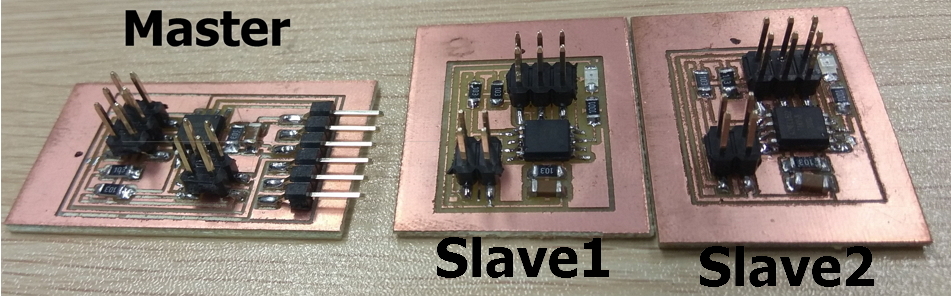
Here is the hero shot of the I2C boards:
Video shot of the boards working:
Downloads
I2C master Schemetic:Here
I2C master Board:Here
I2C node Schemetic:Here
I2C node Board:Here
Arduino: Master, Slave1, Slave2