Exercise 8 - Embedded Programming
Reading the Datasheet - Attiny85 (Read here!)
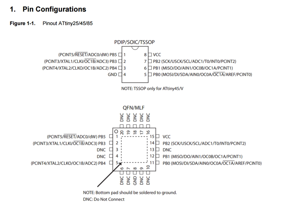
Reading thru the Datasheet, it shows plenty of information of the ATTINY85 which I used for the hello board.
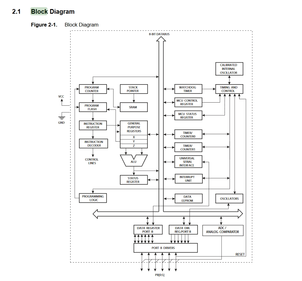
It also shows the block diagram of the chip. I am actually quite surprise that such a small chip, and so many logic gates and components all cramped into one chip.
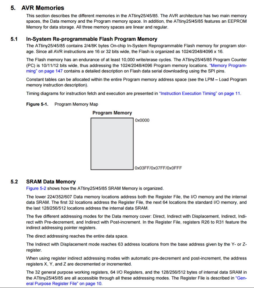
We can also check out the memory differences between Attiny45 and Attiny85
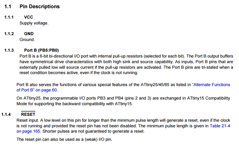
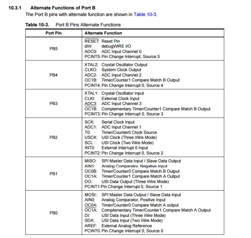
Interestingly, the chip has 6 I/O (Input Output) pins that we can configure and to play with.
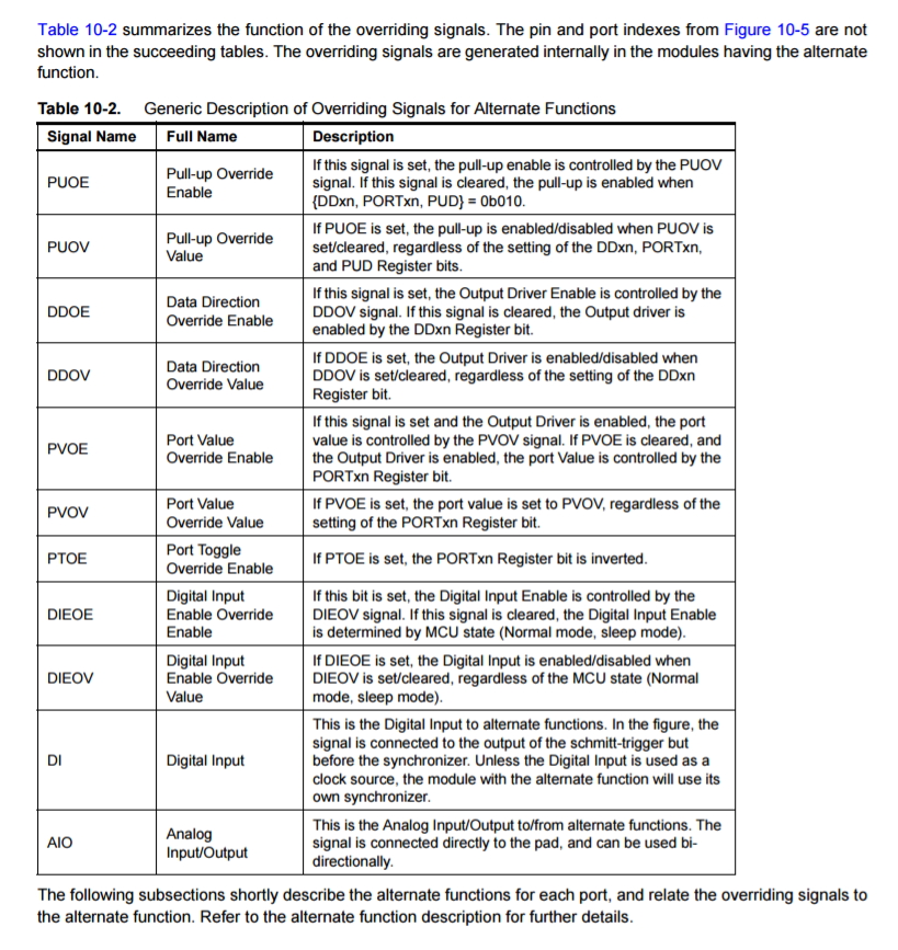
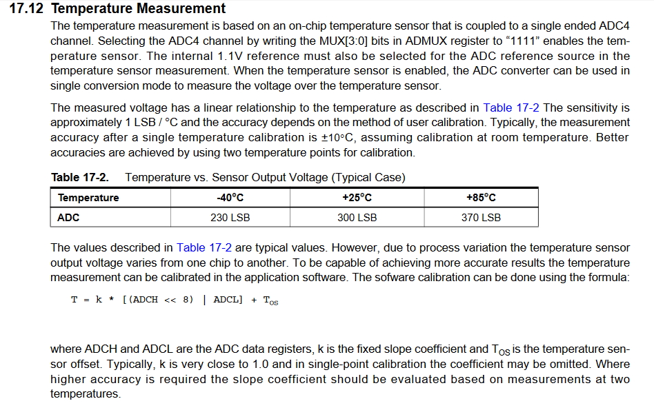
Based on the Datasheet it also says that ATTINY85 has a build in temperature sensor, and with some coding and lead assignment, I am able to activate the sensor.
The on-chip temperature sensor is selected by writing the code “1111” to the MUX[3:0] bits in ADMUX register when the ADC4 channel is used as an ADC input.
I am beginning to imagine how am I gonna implement it into my Final Project...
Combining the FABISP with HELLOWORLD BOARD
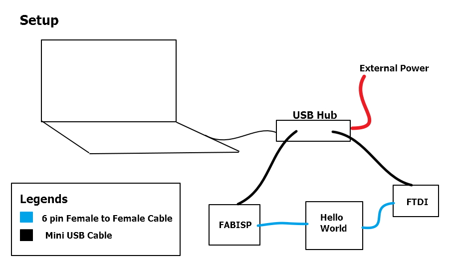
Previously on exercise 6, program our board using the Arduino and Arduino IDE. What we need are:
- USB Hub with optional power
- 2 x Mini USB cable
- 2 x 6 pin Female to Female cable
- 1 x FABISP
- 1 x HELLO BOARD (ATTINY 44/45)
- 1 x FTDI board
Here is a sample of how it looks like when including the FTDI board to communicate with the computer.
This week's assignment is similar to what we have done in week 6. Using it to display Blinking lights and Press button to turn on and off lights.
Blink code
				/*
			  Blink
			  Turns on an LED on for one second, then off for one second, repeatedly.

			  Most Arduinos have an on-board LED you can control. On the UNO, MEGA and ZERO
			  it is attached to digital pin 13, on MKR1000 on pin 6. LED_BUILTIN is set to
			  the correct LED pin independent of which board is used.
			  If you want to know what pin the on-board LED is connected to on your Arduino model, check
			  the Technical Specs of your board  at https://www.arduino.cc/en/Main/Products

			  This example code is in the public domain.

			  modified 8 May 2014
			  by Scott Fitzgerald

			  modified 2 Sep 2016
			  by Arturo Guadalupi

			  modified 8 Sep 2016
			  by Colby Newman
			*/


			// the setup function runs once when you press reset or power the board
			void setup() {
			  // initialize digital pin LED_BUILTIN as an output.
			  pinMode(PB1, OUTPUT);
			}

			// the loop function runs over and over again forever
			void loop() {
			  digitalWrite(PB1, HIGH);   // turn the LED on (HIGH is the voltage level)
			  delay(1000);                       // wait for a second
			  digitalWrite(PB1, LOW);    // turn the LED off by making the voltage LOW
			  delay(1000);                       // wait for a second
			}
What this code does?
This is to define PB1 as an output.
			void setup() {
			  // initialize digital pin LED_BUILTIN as an output.
			  pinMode(PB1, OUTPUT);
			}
This is in a loop where it is running nonstop. It gives a 'HIGH' which is means to turn 'ON' PB1(which is the LED), then it will delay for 1000 milli second (which is 1 second). Then it turn off for another 1 second.
			// the loop function runs over and over again forever
			void loop() {
			  digitalWrite(PB1, HIGH);   // turn the LED on (HIGH is the voltage level)
			  delay(1000);                       // wait for a second
			  digitalWrite(PB1, LOW);    // turn the LED off by making the voltage LOW
			  delay(1000);                       // wait for a second
			}
Button code:
			/*
					  Button

					 Turns on and off a light emitting diode(LED) connected to digital
					 pin 13, when pressing a pushbutton attached to pin 2.


					 The circuit:
					 * LED attached from pin 13 to ground
					 * pushbutton attached to pin 2 from +5V
					 * 10K resistor attached to pin 2 from ground

					 * Note: on most Arduinos there is already an LED on the board
					 attached to pin 13.


					 created 2005
					 by DojoDave <http://www.0j0.org>
					 modified 30 Aug 2011
					 by Tom Igoe

					 This example code is in the public domain.

					 http://www.arduino.cc/en/Tutorial/Button
					 */

					// constants won't change. They're used here to
					// set pin numbers:
					const int buttonPin = PB0;     // the number of the pushbutton pin
					const int ledPin =  PB1;      // the number of the LED pin

					// variables will change:
					int buttonState = 0;         // variable for reading the pushbutton status

					void setup() {
					  // initialize the LED pin as an output:
					  pinMode(ledPin, OUTPUT);
					  // initialize the pushbutton pin as an input:
					  pinMode(buttonPin, INPUT);
					}

					void loop() {
					  // read the state of the pushbutton value:
					  buttonState = digitalRead(buttonPin);

					  // check if the pushbutton is pressed.
					  // if it is, the buttonState is HIGH:
					  if (buttonState == HIGH) {
					    // turn LED on:
					    digitalWrite(ledPin, HIGH);
					  } else {
					    // turn LED off:
					    digitalWrite(ledPin, LOW);
					  }
					}
What this code does?
These are setting the global setting. But instead of using the pin name, I've used variable names for it to represent the Pin
			const int buttonPin = PB0;     // the number of the pushbutton pin
			const int ledPin =  PB1;      // the number of the LED pin

			// variables will change:
			int buttonState = 0;         // variable for reading the pushbutton status
This is the setup function where it declares the ledPin as an Output and buttonPin as as an Input.
			void setup() {
			 // initialize the LED pin as an output:
			 pinMode(ledPin, OUTPUT);
			// initialize the pushbutton pin as an input:
			pinMode(buttonPin, INPUT);
					}
In this loop, it will check for the buttonPin to see if it is HIGH or LOW.
If it detects a button press, it will turn on the LED else it will turn it off.
					void loop() {
					  // read the state of the pushbutton value:
					  buttonState = digitalRead(buttonPin);

					  // check if the pushbutton is pressed.
					  // if it is, the buttonState is HIGH:
					  if (buttonState == HIGH) {
					    // turn LED on:
					    digitalWrite(ledPin, HIGH);
					  } else {
					    // turn LED off:
					    digitalWrite(ledPin, LOW);
					  }
					}
The only difference we have this week is to include PuTTy to communicate my board and my PC. Therefore the requirement to have the FTDI board.
here is the setup:
This is how it is done:
1) Download and install PuTTY.
2) Write code to produce output via RX and TX (for my example, PB3 as RX and PB4 as TX)
				#include < SoftwareSerial.h>
				// constants won't change. They're used here to
				// set pin numbers:
				const int rx=PB3; // on ATTINY 85, RX is on PB3
				const int tx=PB4; // on ATTINY 85, RX is on PB4
				const int buttonPin = PB0;     // the number of the pushbutton pin
				const int ledPin =  PB1;      // the number of the LED pin
				int val = 0;
				int old_val = 0;
				int state = 0;
				int flag = 0;

				SoftwareSerial mySerial(rx,tx);
				// variables will change:

				void setup() {
				  mySerial.begin(9600);
				  // initialize the LED pin as an output:
				  pinMode(ledPin, OUTPUT);
				  // initialize the pushbutton pin as an input:
				  pinMode(buttonPin, INPUT);
				}

				void loop() {
				  if(mySerial.available() > 0){
				    state = mySerial.read();
				    flag=0;
				  }
				  // read the state of the pushbutton value:
				  val = digitalRead(buttonPin);

				  // check if the pushbutton is pressed.
				  // if it is, the buttonState is HIGH:
				  // resets written counter to 0
				  if ((val == HIGH) && (old_val == LOW)) {
				    state = 1 - state;
				    flag = 0;
				    delay(10);
				  }
				  old_val = val;

				  if ((state == 1) && (flag == 0)) {
				    digitalWrite(ledPin, HIGH);   // turn the LED on (HIGH is the voltage level)
				    mySerial.println("led is on!");
				    flag = 1;
				  } else if ((state == 0) && (flag == 0)) {
				        digitalWrite(ledPin, LOW);
				        mySerial.println("led is off!");
				        flag = 1;
				        }
				    else {
				      //do nothing
				    }


				}
What this code does?
These are setting the global setting. But instead of using the pin name, I've used variable names for it to represent the Pin. And of course, we have to add a SoftwareSerial.h as it is required to show it on our Serial Monitor of Arduino IDE. I also added some variables as a flag or state to store the value. PB3 and PB4 are the RX and TX of the Attiny 85.
				#include < SoftwareSerial.h>
				// constants won't change. They're used here to
				// set pin numbers:
				const int rx=PB3; // on ATTINY 85, RX is on PB3
				const int tx=PB4; // on ATTINY 85, RX is on PB4
				const int buttonPin = PB0;     // the number of the pushbutton pin
				const int ledPin =  PB1;      // the number of the LED pin
				int val = 0;
				int old_val = 0;
				int state = 0;
				int flag = 0;

				SoftwareSerial mySerial(rx,tx);
				// variables will change:
Next is to setup the Serial with the BitRate 9600 and setting ledPin as OUTPUT and buttonPin as an INPUT.
				void setup() {
				  mySerial.begin(9600);
				  // initialize the LED pin as an output:
				  pinMode(ledPin, OUTPUT);
				  // initialize the pushbutton pin as an input:
				  pinMode(buttonPin, INPUT);
				}
In this loop, it will check if the serial is available, if so, it will then set read the button input and then it will do a comparative check for the state, flag and a delay of 10ms for debouncing of the button. If the state is set as 1 and the flag is 0, it will turn the LED on and print the serial a line "led is on!"
Then if both the state and flag condition are 0, it will turn off the led and show it on the serial monitor that the led is off.
				void loop() {
				  if(mySerial.available() > 0){
				    state = mySerial.read();
				    flag=0;
				  }
				  // read the state of the pushbutton value:
				  val = digitalRead(buttonPin);

				  // check if the pushbutton is pressed.
				  // if it is, the buttonState is HIGH:
				  // resets written counter to 0
				  if ((val == HIGH) && (old_val == LOW)) {
				    state = 1 - state;
				    flag = 0;
				    delay(10);
				  }
				  old_val = val;

				  if ((state == 1) && (flag == 0)) {
				    digitalWrite(ledPin, HIGH);   // turn the LED on (HIGH is the voltage level)
				    mySerial.println("led is on!");
				    flag = 1;
				  } else if ((state == 0) && (flag == 0)) {
				        digitalWrite(ledPin, LOW);
				        mySerial.println("led is off!");
				        flag = 1;
				        }
				    else {
				      //do nothing
				    }


				}
3) In PuTTY, we set it as Serial communication, for my example, my FDTI board is in COM7, make sure the Speed is set to 9600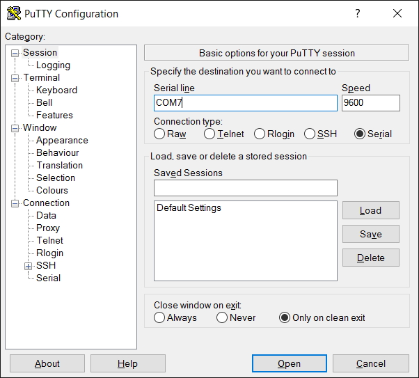
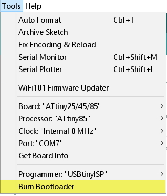
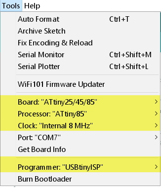
4) We are going to burn a bootloader, thus select burn bootloader
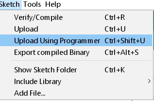
5) Then we, upload the code using programmer via Arduino IDE.
6) see the Magic!
Atmel Studio
Check if the wiring is correct again, we can do this
you can check your wiring and that you installed both AVRDUDE and the driver correctly. Open a console and type
avrdude -c usbtiny -p t85 -n -v
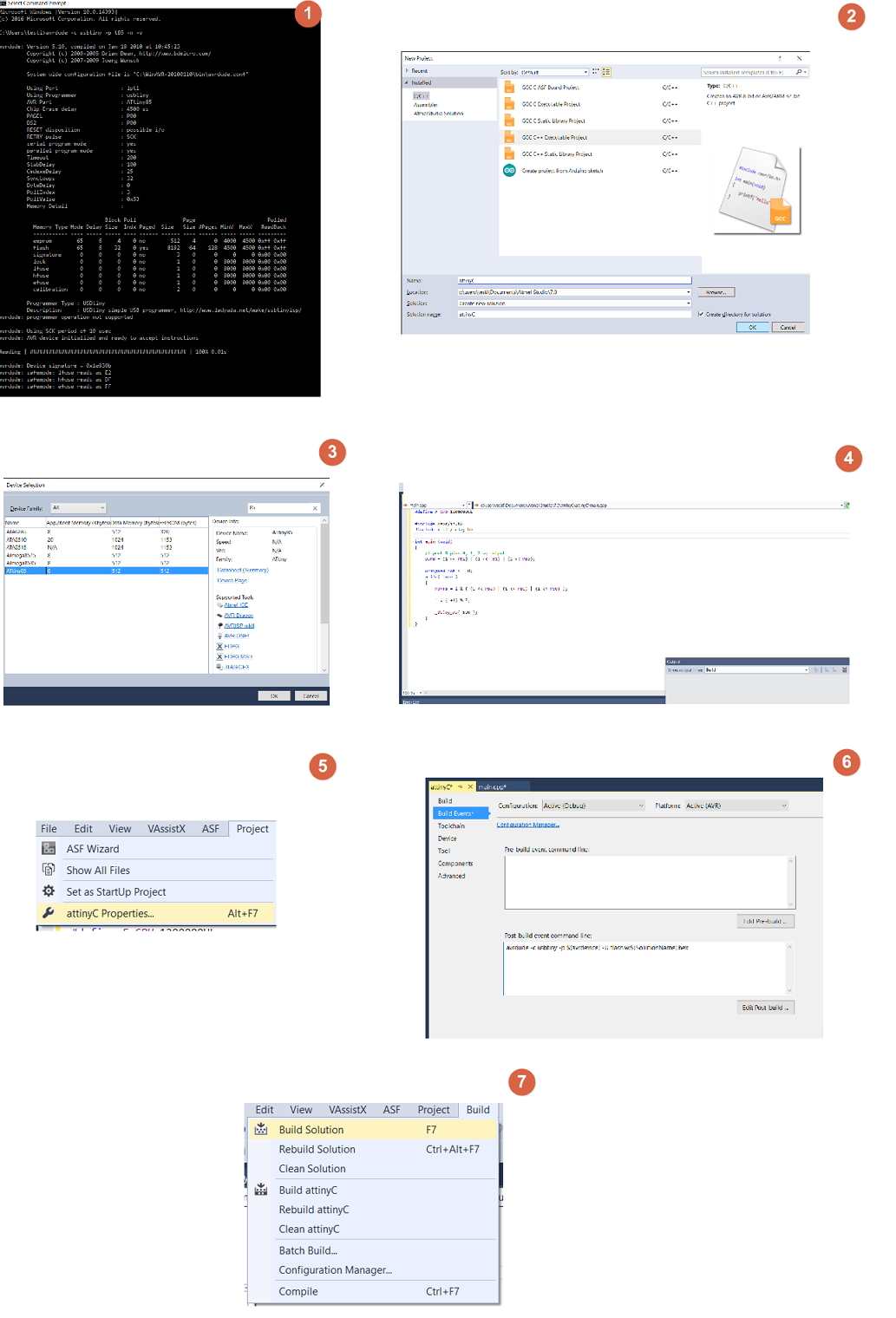
1) Launch AtmelStudio, choose File->New->Project. Select "GCC C++ Executable Project" and choose a name and a directory below.
2) After clicking OK a 'Device Selection' dialog will appear, choose 'ATtiny85' and click OK.
3) To make programming the microcontroller even easier, click Project-> "name of project" Properties, choose 'Build Events' on the left, and add
avrdude -c usbtiny -p $(avrdevice) -U flash:w:$(SolutionName).hexThis will execute AVRDUDE and copy the binary file of our program to the microcontroller after the program was built successfully.
4) hit F7 ("Build Solution"). If the project is set up correctly, you should see something like this:
Downloads
Blink- downloadButton - download
Button with Terminal- download
C++ - download