Exercise 7 - Computer-controlled Machining
Making Something BIG
This week is an exciting one, I have many things I want to do, but something in my heart that I really want to do to improve my home's Desktop.
There are 2 Monitors on my desktop for dual screen purposes and it is occupying quite a big space when combined, plus my desktop is also occupying too much space.
This is my plan
To create a monitor stand for my desktop.
As my layout is slightly tilted to face me, I designed the table top to be at an angle. I measured the size of my TV and monitor's base, length, height and thickness of the 2 displays.
I drew rough models of my TV and Monitor as a reference for my monitor stand.
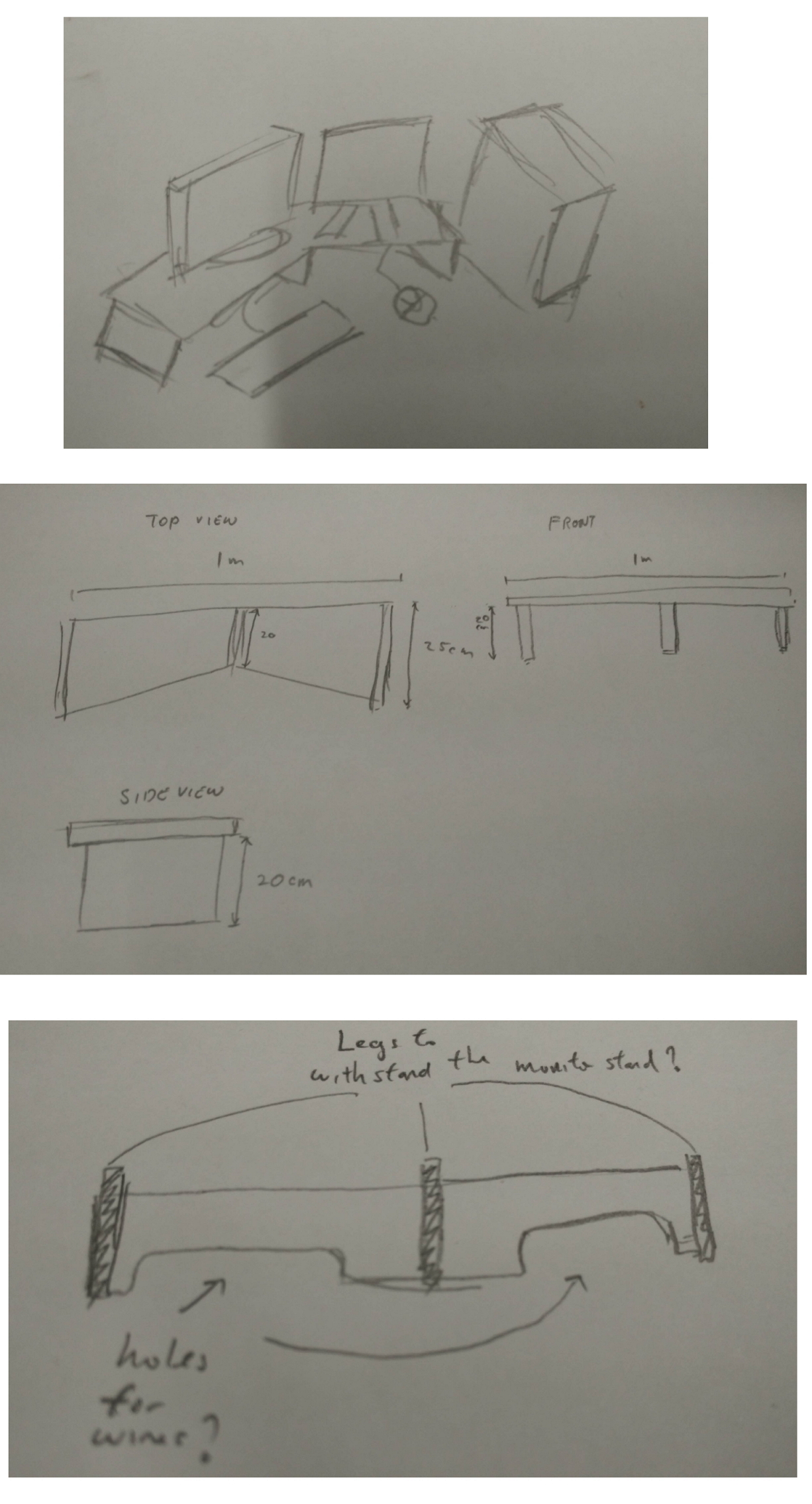
I gave a rough size of 100cm on the length, 25cm on the width and 20 cm on the height (without the material thickness).
After designing for a while, I was worried that my console may not withstand the weight. Therefore I added a rib at the back of the stand to make the monitor stand stronger. As this week's making something BIG, we are not supposed to use any screws or glue to help us, therefore my design requires to be press-fit.
Test Cut + Fusion 360 Model & CAM(Computer Aided Machinery)
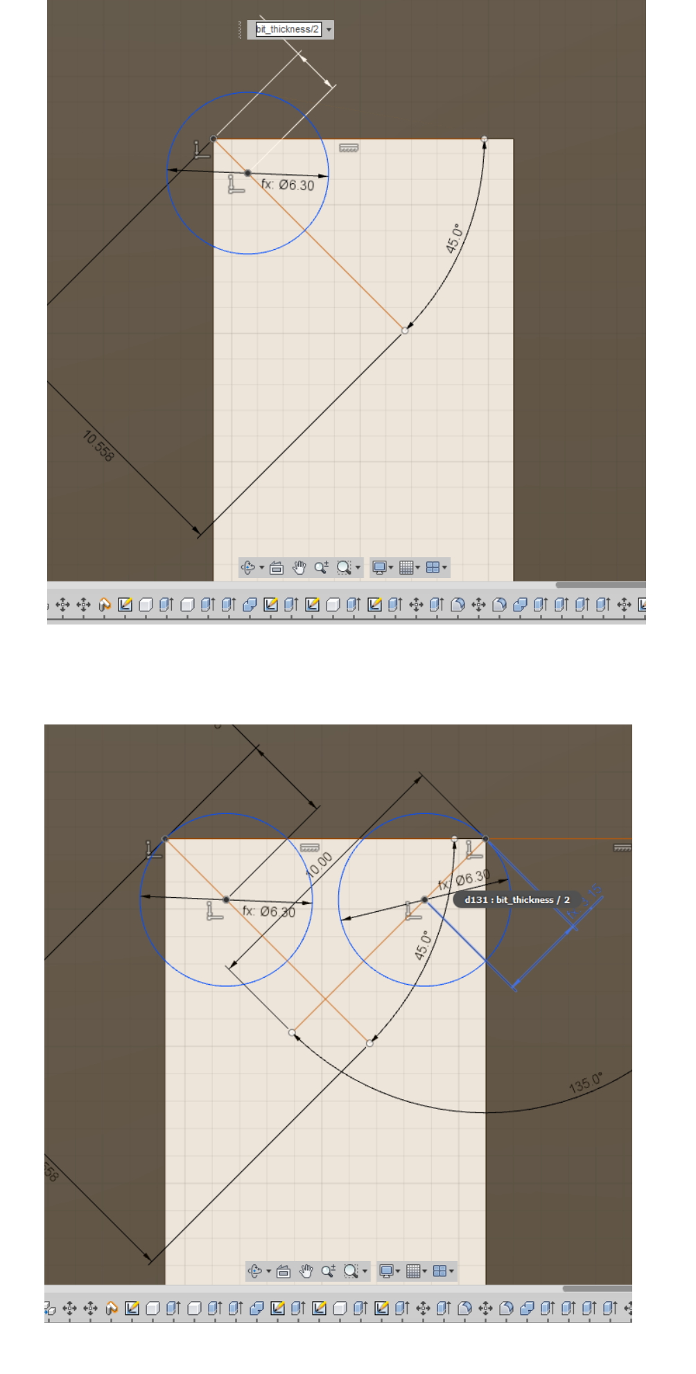
I designed the test cut in Fusion 360 and I designed 2 different designs to test 1 with Dogbone and one without.
So what is Dogbone?
Dogbones are said to help fittings to fit nice and snug instead of forcing the tabs into the slots.
Watch this tutorial on how to create a press fit stool with dogbones:
I am impressed with Fusion 360 on the ability to have a package that allows modelling and CAM all in one page.
Before I bring the files to CAM to do some settings for it to be cut, I measure the plywood that I need to cut, and go back to Fusion 360 using Parametric to change the values of wood thickness. This is important so as to scale the slots accordingly on every slots.
After designing the 2 sets of sample slots with 0.1mm incremental, I send the file to CAM mode.
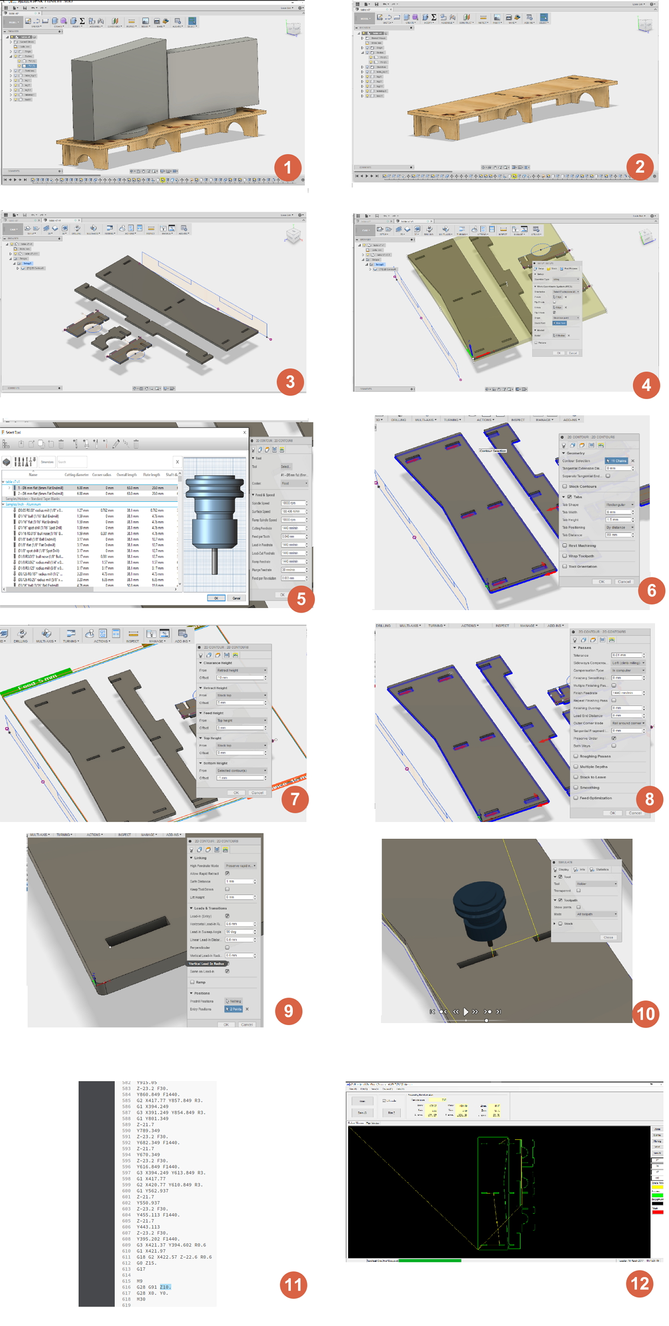
These are the steps that I've done to setup the CAM settings.
- First, I click on setup to do the following settings for my router.
- I have to take note on the X, Y and Z axis on the file, as that would be the origin and that is where my Router machine will cut.
- Next, I will click on 2D Contour, that is where I am able to cut my model.
- These are the settings I've set for my router. I also make sure the Tool used is a 6mm End Mill, which can be found on the Library itself.
- Next I will select the bottom outline of my models. Making sure it is in BLUE and the direction of the arrows. (point in = Inside cut, point out = Outside cut). I also select the insides cut first and then the outside of the mode, remember to select the "Preserve order", this check box is important! The reason is, Fusion 360 will auto generate the toolpath with may cut outsides first and then the insides last, this will cause the wood to slip and cause serious injury or mis-cut.
- Next, I enable Tabs, these tabs are extremely helpful when cutting the outline, it is designed like a preforated outlike (black to cut and the space to skip). It helps to "hold down" the object. For this example, my settings are set at 6mm width, and 2mm height @ 80mm distance. I also set Multicut of 7mm to try it out (optional, but it's best to have it to relief stress from the bit
- After clicking OK to let it generate a tool path, I click on "Simulate" to show me the path. I make sure the direction is correct and the inners are cut first before the outer. And most importantly, the Tabs are also being cut.
- Finally I click to "Generate code" for my cutting route, it will generate a G-code for the routing machine. My guru mentioned to use to adjust the Z Axis on the code before the code ends to prevent accidental cut on the surface of my cut out. I also make sure the file saved is in ".tap"
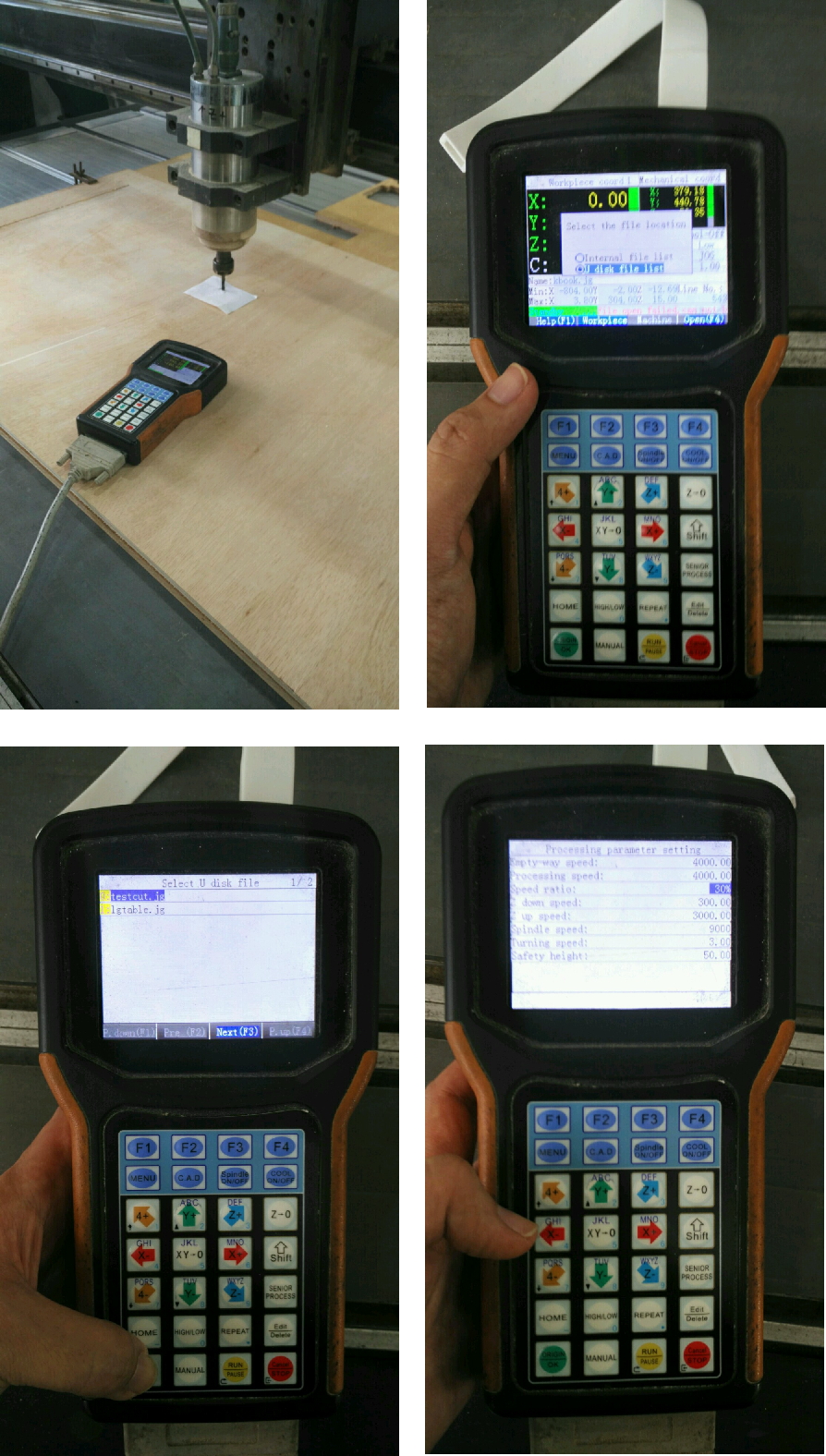
JG & CNC
With the .Tap file, I need to generate .JG file for the Router machine that we have. Unfotunately it only reads JG files, I preview my files on JG and confirm with the cut, I saved the file as a .JG.Next, I saved it into a thumb drive and bring it to the Router machine's controller. I had to adjust the XY Origin first and once i'm confortable with the location, I bring down the Z axis to zero it. One thing I realised on the machine, it didn't take in the values of my Feed rate, spin rate from Fusion 360. I had to manually key in the values from the console.
I will need to understand three values: Speed, Feedrate and Depth when deciding how to cut a new material with a new tool.
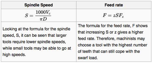
Taken from https://en.wikipedia.org/wiki/Milling_cutter#Using_a_milling_cutter
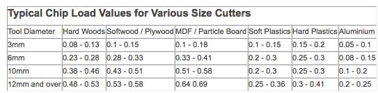
I am using a 2 flute 6mm end millcutter, spindle speed at 8000 rpm on softwood
Feedrate = chip load x rpm x no of flute
= 0.28 x 8000 x 2 = 4480mm per minute
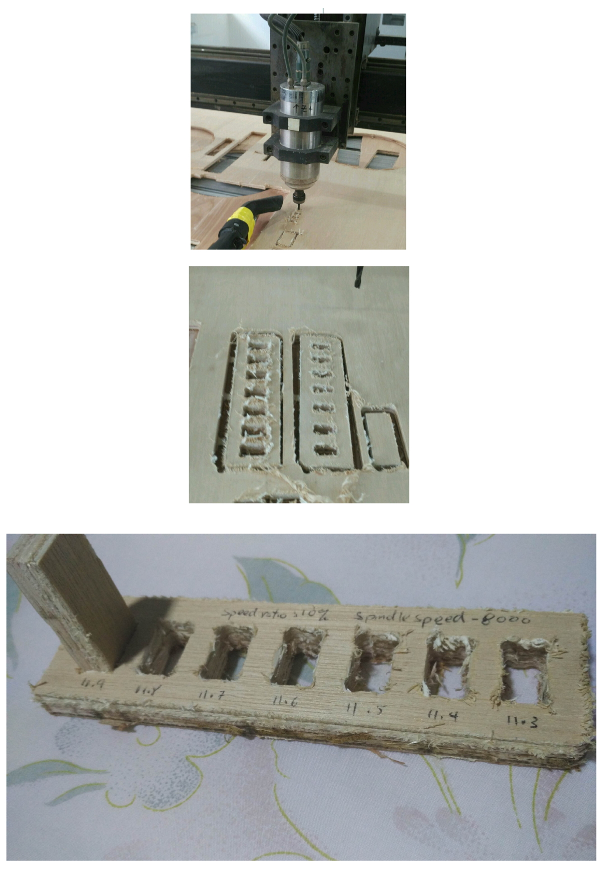
I clamped the ply wood firmly and screwed in some screws to hold it down.
After cutting my models, I was wondering how come it created so much wood burrs, even at a low speed and at 8000 rpm spin speed.
I was also able to remove my cut out with a tap with the mallet without using the chisel.
I cleaned up the male part of the fitting and only managed to slot in to the last slot of 11.9mm.
With that, I know the tolerance value of my plywood. Only the one with Dogbone fits nice and snug but the one without dogbone is impossible to slot it in @ 11.9mm.
Back to design board - Fusion 360
I designed my Console Table on Fusion 360. I am still getting the hang of it, hence the browser side is still quite messy.
I remeasured the Plywood that I will be using as I realised all plywood has different thickness, check the grain direction of the plywood to be cut along the beautiful top grain.
With that I go back to Fusion 360 to change the orientation and resize the wood thickness in the Parametric design.
With that all set, I followed the steps I did for the test cut in preparing and proceed on to cut.
Mistakes and Experience gained
1) When I was cutting the inner side of my cut out, I realised I made a mistake, the origin was too close to the edges for comfort, hence I stopped the cut and reset a new XY Origin.2) After my first cut on the Table top, the board shifted, it came loose from the tabs! But on my smaller test cut, it didnt break loose. I came to understand, maybe a bigger cut requires a thicker tab to hold it as it would be stronger.
3) I also realised that middle of the cut, the board starts to wobble, that is a mistake! I should screw in the board to the sacrifical board below to stablise it
4) When I was trying to cut my back rib of the table, the cut out was too close to the Table top and I had to stop the cut as the cut out popped out from the cavity and it was too risky to carry on. I had no choice but to rearrange it and cut the remaining legs and the back rib seperately.
Results
Turn out the cut was what I expected! Minus the messy burrs, I had to do some clean up with the help of a penknife (to remove the spiky burrs), orbital sander to remove splinters on the Plywood and a Dremel Rotary tool to remove burrs in the dogbone and slot.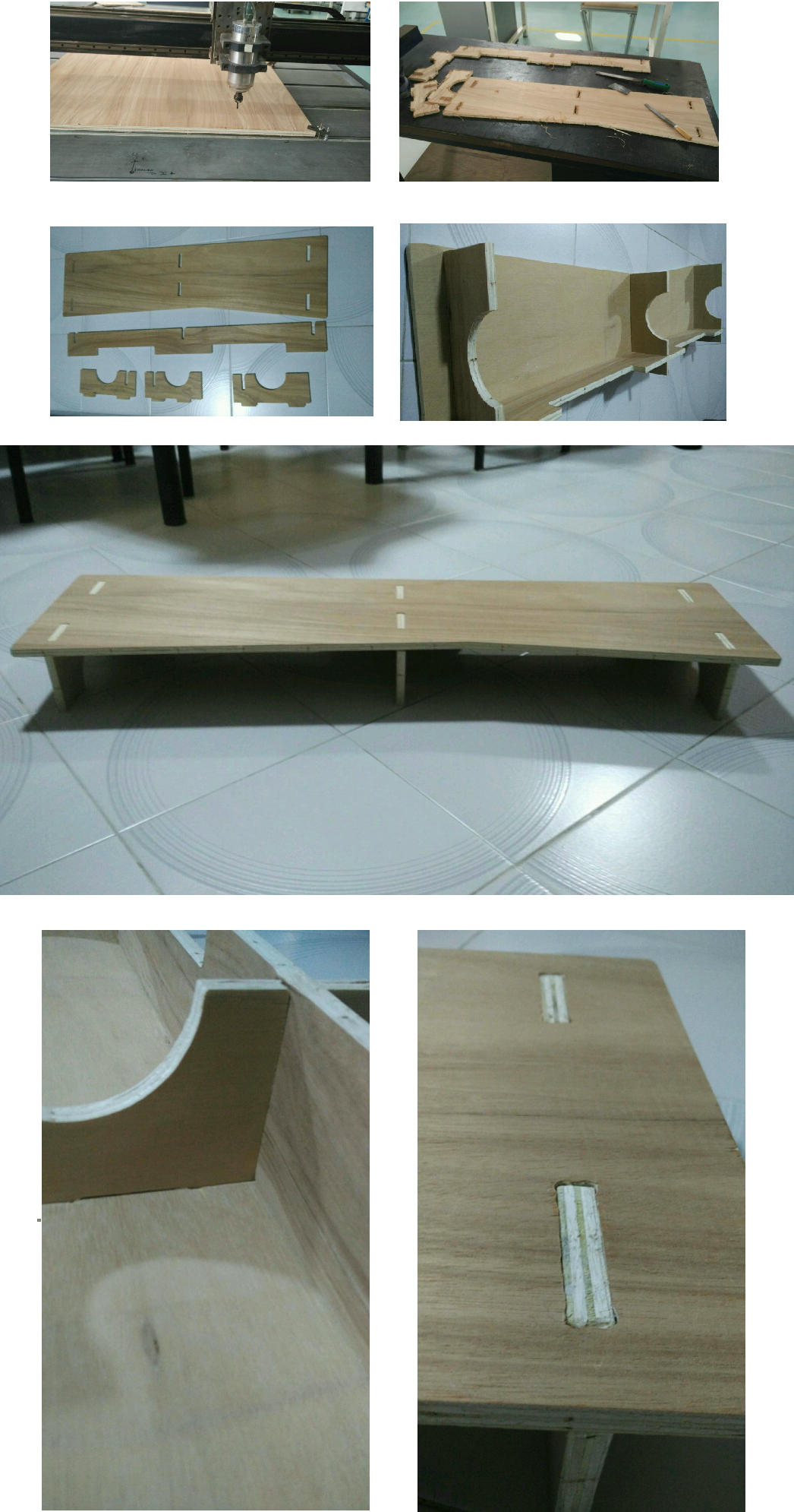
It was a messy clean up, but a satisfactory one. Now what it lacks is a good coat of laquer to protect it, I will find time to get a laquer spray and give it a good coat to show the beautiful grain and of course to protect it!
I was so excited that day, I had to quickly assemble it and put it to good use for my desktop!
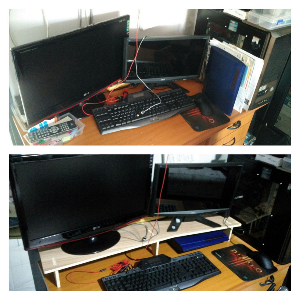
After assembling, everything fits well and it looks pretty awesome and now my Desktop looks so much neater! Except one problem.
I forgot to measure the length of my keyboard! Well, with this experience gained, I can always go back to the drawing block and redesign my Monitor Stand!
I really enjoyed this session thorougly!
Now for the next idea...
Probably an electric Guitar? :P
Downloads
Note: I recommend you to download the Fusion file and generate the toolpath yourself. As different machine differs, it is safer to do this method
Testcut:Fusion
Tabletop:Fusion