Exercise 6 - Electronics Design
This week we are to design a "Hello World" board. I pretty much enjoy this exercise as I get to work on soldering the SMD components.
I first started trying and practice it on EAGLE to draw my schematic and drawing the board. Using Neil's sample diagram.

The diagram above shows how I added components in Eagle and instead of using the current library, we used the Fab library supplied by Neil.(NOTE: this is for ATTINY 44.)
You can find it here. Add it to your Eagle Library List.
Then its all about schematic linking. Sorting the components like what Neil has give us.here.
Our board
But instead of using ATTINY 44, we are told to use to use ATTINY 45, but was given ATTINY 85 instead.
I did a search on ATTINY 85 datasheet and apparently, they belong to the same family and the pins are the same.
The difference between ATTINY 45 & ATTINY 85?
In-system programmable Flash (4Kb vs 8kB),EEPROM (256 bytes vs 512 bytes)and the same SRAM of 256 bytes. Other than that, its the same chip. Read / download the Datasheet here We got the schematic on how the circuit should be linked and design.
Components list
1x Microcontroller Attiny45/85
1x Programming Header J1, 2x3 (AVRISPSMD)
1x FTDI Header J2, 1x6 (FTDI-SMD-HEADER)
1x Resistor 499 (RES-US1206)
2x Resistors 10K (RES-US1206)
1x Capacitor 1uF (CAP-US1206)
1x LED (LED1206) Red
1x 6mm Switch button
I find this list requires lesser components as compared to the t44 version, as it does not have a resonator, because it uses it's inbuild clock.
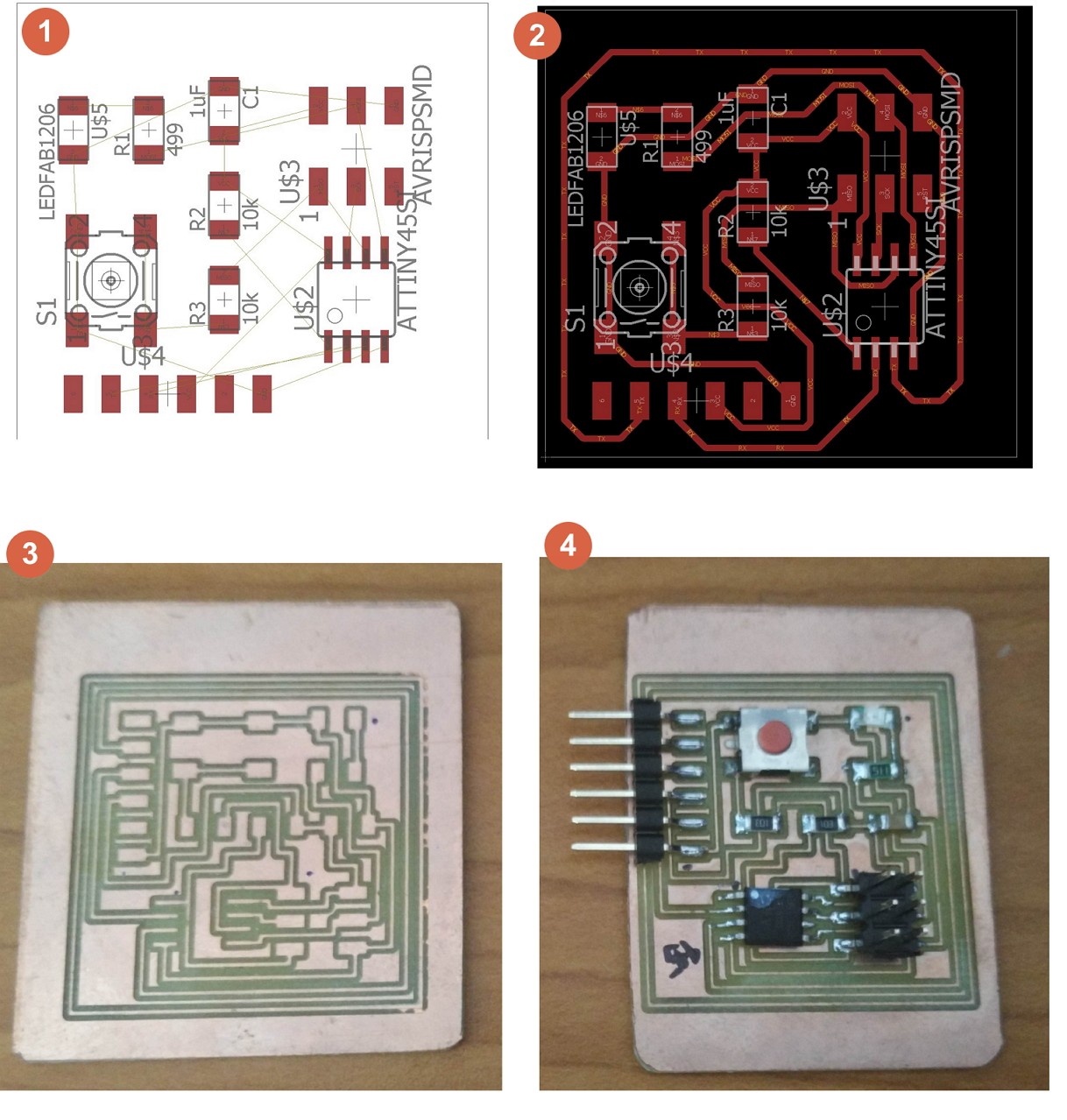
Thus with the above components and some guide, I designed the board with the schematics done in Eagle.
Process
With some help from my course mate Jeff, I designed circuit in schematic, convert it in board, routing the tracks, milling it out and soldering the components into the circuit.I had to struggle a bit as it was 12 years ago when I learnt electronics.
In EAGLE, there are helpful tools like ERC function, it helps you check your schematic for unconnected pins or pins that is open.
And DRC function where you are able to check your tracks after routing for clearance issues.
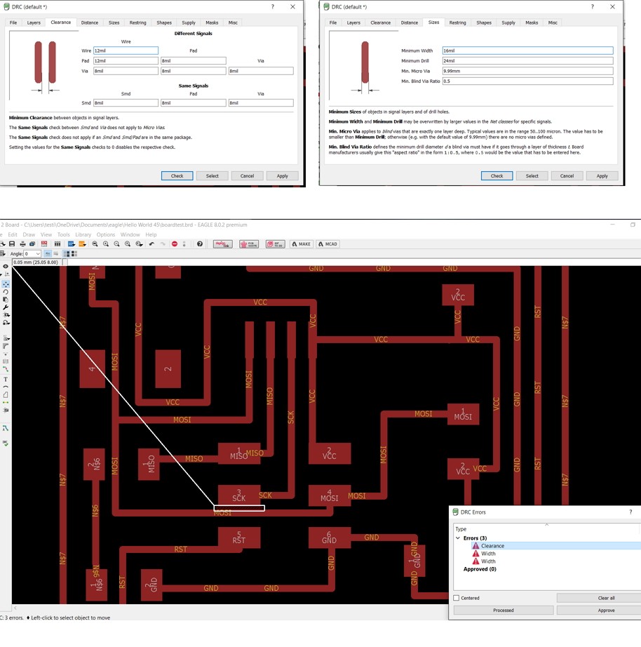
I challenged myself to create a small board making it more compacted.
My design also changed from 45 degree track to all 90 degree track as my guru told mentioned that chemical etching requires 45 degree. Milling can handle 90 degrees and easier to mill.
After soldering, I tested the board by using the Multimeter for short, and finished it off with some hot glue for the pins, to prevent it from ripping out the copper board when pulling out pin connectors.
Programming
Then, we program an Arduino board as an AVRISP. Connect the wires to the Hello world board.| Uno | ATtiny45/85 | |
|---|---|---|
| 10 | <--> | Reset |
| 11 | <--> | MOSI |
| 12 | <--> | MISO |
| 13 | <--> | SCK |
| 5V | <--> | VTG |
| GND | <--> | GND |
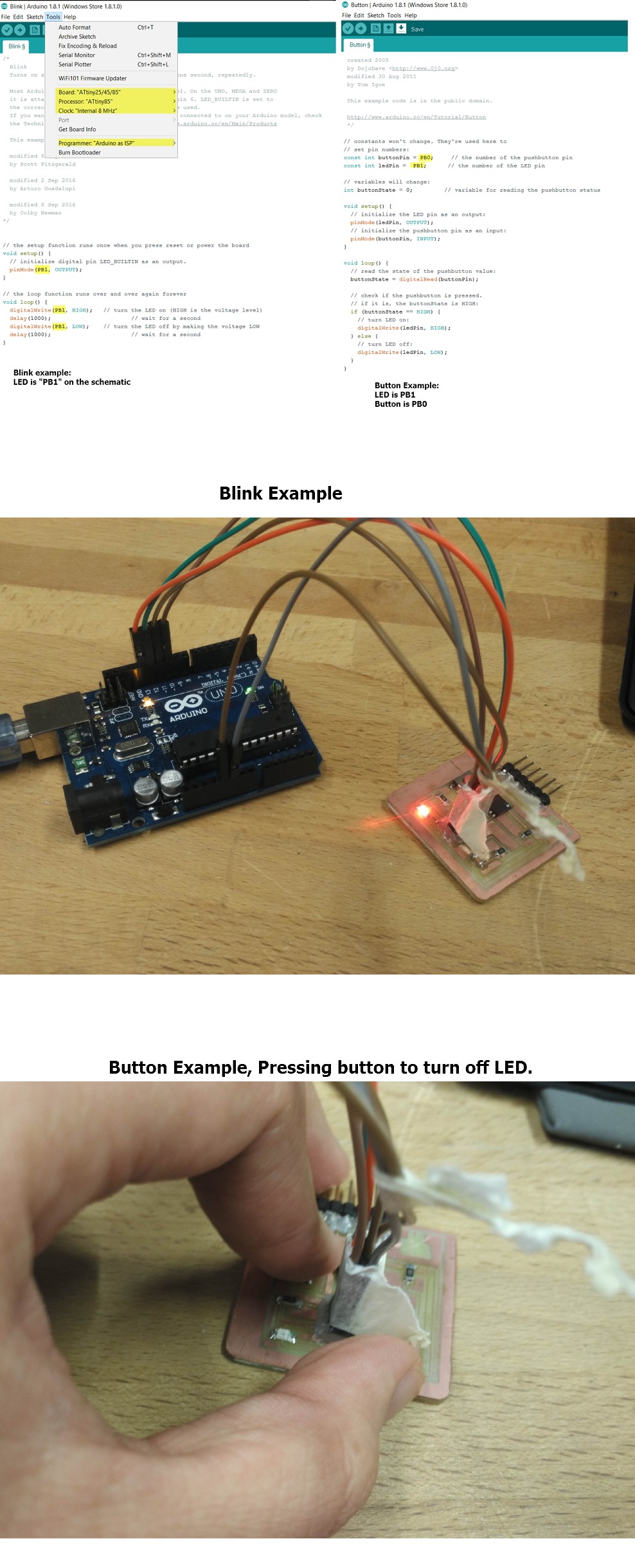
After connection, I used the Arduino IDE and open up the Example Code>Blink and change the LED to "PB1"
Then I change the settings of my ARDUINO IDE for it to Program the "ATTINY 85 @ 8MHz".
Programmer I set it as "Arduino as ISP".
Thoughts
Got to be honest, I kinda enjoy this exercise. the routing of the PCB, checking for DRC for clearance, soldering the components to the board and getting it work with the Arduino board. I'm looking forward to design something on my own in the future.
Links to my schematic and board design:
Schematic, Board, Etch file: Zip