08. Embedded Programming
read the data sheet
I go to the schedule pages in archive.fabacademy.org and downloads it and read it
Since I am using the Attiny44 so i find the Pins of the ATtiny44's picture:
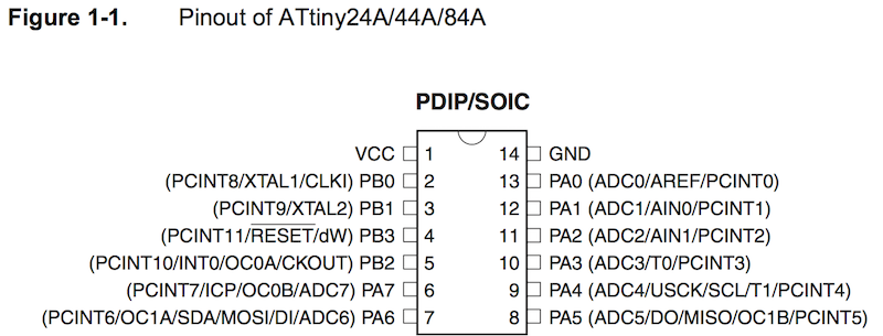
And found that the lEDpin is 7 - which will be used when programming it
The brief summary of the datasheet:
1. High endurance :10,000 Write/Erase Cycles -- 100,000 Write/Erase Cycles (So I can test my code and circuit frequently without any being worried about it)
2. One 8-bit and One 16-bit Timer/Counter with Two PWM Channels, I can use PWM on it
3. Universal Serial Interface -- friendly for me, since I don't have much knowledge of it.
4. Operating Voltage:  1.8 – 5.5V , I can use my computer to power it.
5. Speed Grade: 0–4MHz@1.8–5.5V – 0–10MHz@2.7–5.5V – 0–20MHz@4.5–5.5V
6. Oscillator Type : Internal(128 kHz & 8 MHz) and External (20 MHz) -- useful while choosing oscillator in arduino
7. 12 general purpose I/O lines
use arduino to code the board
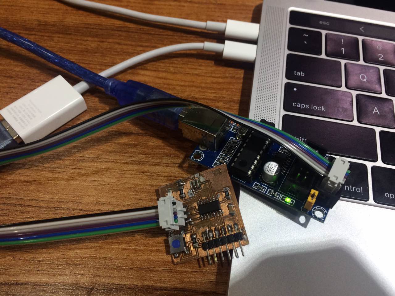
I linked my board with the Arduino board - ( since I can't find my FABISP board that have been created before )
Then open the arduino in your computer:
Since there is no information about the Attiny44 in Arduino so I need to clone it from the remote repositories:
What I did:
Open the Arduino > Preference.
Goto Additionak Boards Manager URLS and Add:
https://raw.githubusercontent.com/damellis/attiny/ide-1.6.x-boards-manager/package_damellis_attiny_index.json
Click on "OK" and save my changed
Then goto the toolbar menu > Tools
Select the Board: "Attiny24/44/84"
Choose the Processor: "Attiny44"(The Processor I used)
Choose the Clock: "External 20 MHz"(Since I used it in my board)
And choose the programmer: USBtinyISP ( Since I used this one to burn my borad. )
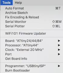
Then click on Burn Bootloader.
And you will see it showed Done burning - if something is wrong, check the previous selections and your board.
Then click on Verify and Upload it to your board.
Here is what I did:
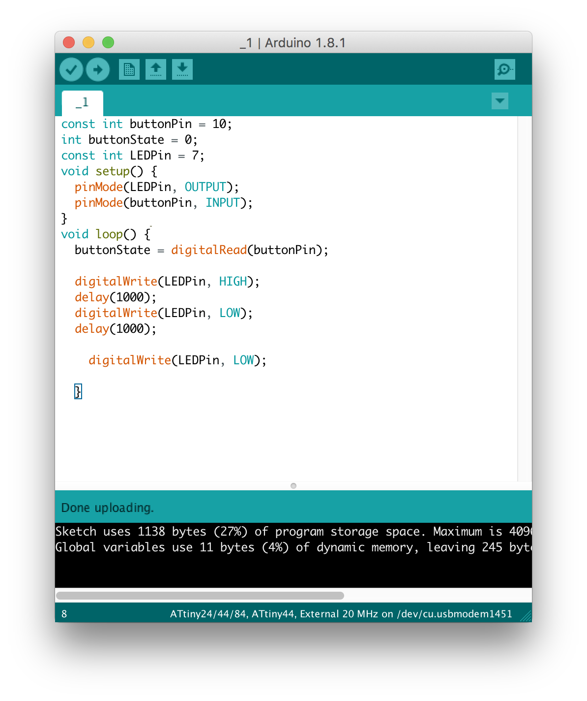
what I code for my board:
After reading the Attiny44 data sheet, I found: The LEDPin is 7 in Attiny44.
const int buttonPin = 10;
int buttonState = 0;
const int LEDPin = 7;
void setup() {
  pinMode(LEDPin, OUTPUT);
  pinMode(buttonPin, INPUT);
}
void loop() {
  buttonState = digitalRead(buttonPin);

  digitalWrite(LEDPin, HIGH);
  delay(1000);
  digitalWrite(LEDPin, LOW);
  delay(1000);

    digitalWrite(LEDPin, LOW);

  }
And here you will see the programmed board:
Modifitcation
The global instructor points out a mistake of my homework, I haven't used the button state.
So, I remake my board and reprogram it.
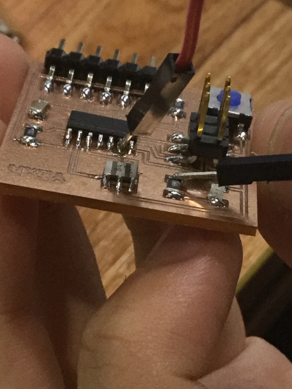
Here is a video of solidering
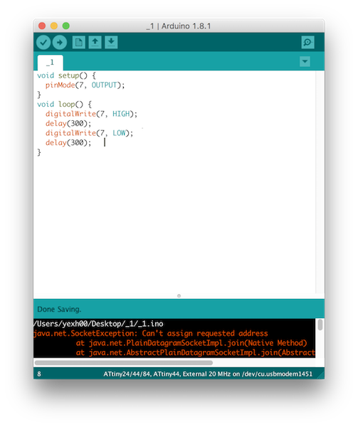
Here is the arduino code for it:

const int buttonPin = 3;
int buttonState = 0;
const int LEDPin = 7;
void setup() {
  pinMode(LEDPin, OUTPUT);
  pinMode(buttonPin, INPUT);
}
void loop() {
  buttonState = digitalRead(buttonPin);
  if(buttonState == HIGH) {
    digitalWrite(LEDPin, HIGH);
  delay(100);
  }
  else{
     digitalWrite(LEDPin, LOW);
  delay(100);
  }
}
But, after finishing programming, I found it still don't work, and I check the circuit and find that the lED doesn't link to the Pin6
So, I adjust it:
And here is the video of it