15. Networking and Communications
design the board with wifi 2.4g
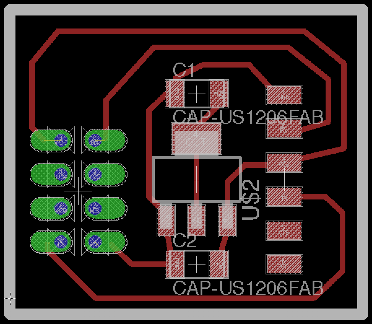
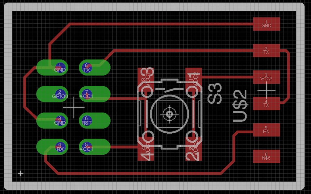
I used the Eagle to design my board - since there are some ESP-01 in my Lab, I designed a board for it.
The ESP-01 also used the chip, ESP8266EX.
Here you see is the design of my board:
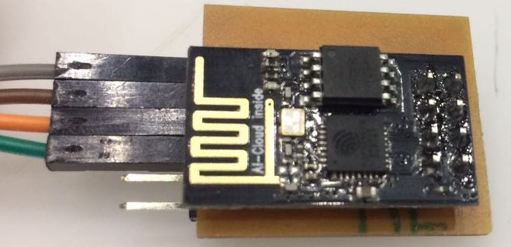
Since the board can only be used in one side - I want to solid the wifi board in the back of my board
here is the ESP-01:
Get the original Eagle design files.
cut the board out and solid the components
As usual, used Fabmodules to calculate the traces and outline
I used the outline to calculate the holes and used the 1/32 inches tools to cut it out - it is really appropriate to use it.
I export 3 png files - since I don't know whether the machine would cut the outline first and the hole then - so I cut the holes before the outline.
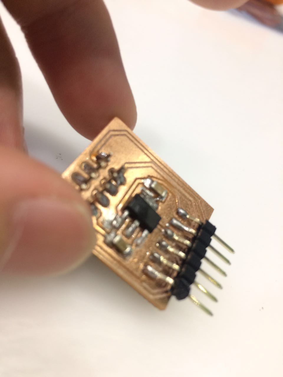
Here is what I got:
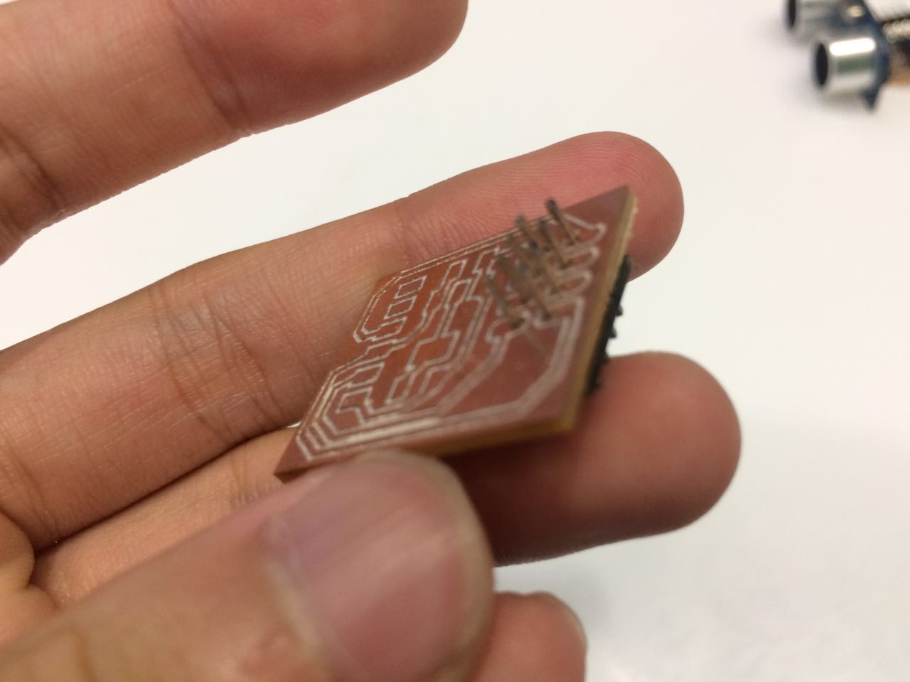
Then solid the components to the board:
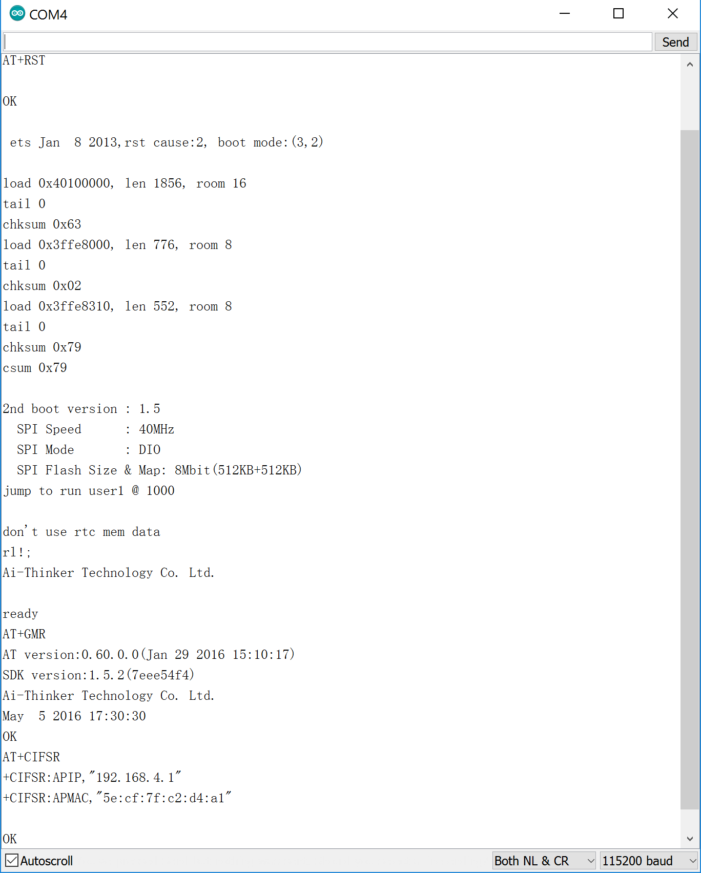
test the board
I used the code in the terminal:
miniterm.py /dev/tty.usbserial-A50285BI 9600
AT
But I got no response then I search it in google and found that the ESP-L01 need to burn the program, so I got the program files on git hub and burn it to my board.
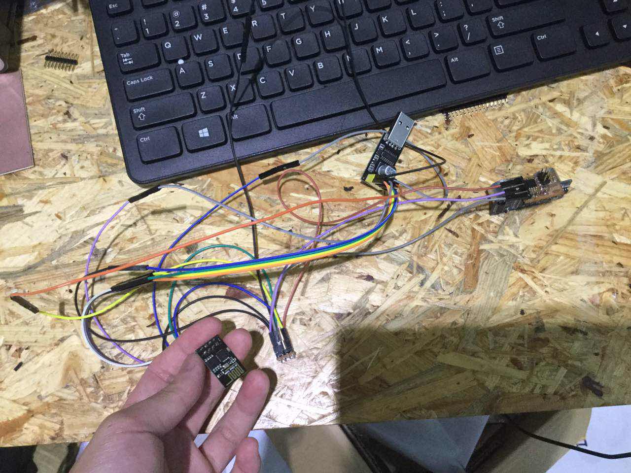
Then, I found there was actually something wrong with my esp 01, so I just bought another one and use it connect to the arduino and work:
use the board
Then I want to connect my input board - the distance board to the wifi board so that I can get the serial data by using the phone connecting to the wifi. - that is what I thought
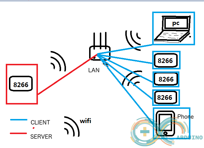
Then, I searched the internet for the information to do that, and I got 2 ways:
1. use the esp8266-01s as a TCP client and then connect it to the servers -
I searched quiet a lot tutorials about this method. It said that there need to
configure the server that can provide a data reservior for the data transported by
the esp8266, and then configure the server that can provide the data visited from the client
like the phone/ pc.
Since I found it is going to be really hard and I don't need to visit my data while the
devices are not with me, I chose not to use this method and tried another one:
2. use the esp8266-01s as a TCP server and connect it to the LAN -
so that I can use other devices like my phones/ pc to connect to the esp8266-01s board with
the distance data collector (the input devices week's homework)
and it needs 2 esp8266-01s - one for the TCP servers, and one for the tranports of the data
collected by the serial - like my distance board
So I used the second method - the tutorial said it needs to program the board A ( the server board) :
#include <ESP8266WiFi.h>
#define MAX_SRV_CLIENTS 3   //max connect clients,8266tcpserver can only support 5 clients connection
const char *ssid = "bao"; ////wifi ssid
const char *password = "123456780w"; //wifi key
WiFiServer server(8266);//random,range:0-65535
WiFiClient serverClients[MAX_SRV_CLIENTS];
void setup()
{
    Serial.begin(115200);
    delay(10);
    pinMode(16, OUTPUT);
    digitalWrite(16, 0);
    WiFi.begin(ssid, password);

    while (WiFi.status() != WL_CONNECTED)
    {
        delay(500);
    }
    server.begin();
    server.setNoDelay(true);
}
void loop()
{
    blink();
    uint8_t i;
    if (server.hasClient())
    {
        for (i = 0; i < MAX_SRV_CLIENTS; i++)
        {
            if (!serverClients[i] || !serverClients[i].connected())
            {
                if (serverClients[i]) serverClients[i].stop();//not connected - release
                serverClients[i] = server.available();//new
                continue;
            }

        }
        WiFiClient serverClient = server.available();
        serverClient.stop();
    }
    for (i = 0; i < MAX_SRV_CLIENTS; i++)
    {
        if (serverClients[i] && serverClients[i].connected())
        {
            digitalWrite(16, 0);//lights up when the link exists

            if (serverClients[i].available())
            {
                while (serverClients[i].available())
                    Serial.write(serverClients[i].read());
            }
        }
    }
    if (Serial.available())
    {
        size_t len = Serial.available();
        uint8_t sbuf[len];
        Serial.readBytes(sbuf, len);
        //push UART data to all connected telnet clients
        for (i = 0; i < MAX_SRV_CLIENTS; i++)
        {
            if (serverClients[i] && serverClients[i].connected())
            {
                serverClients[i].write(sbuf, len);  //transport all data to the clients
                delay(1);
            }
        }
    }
}
void blink()
{
    static long previousMillis = 0;
    static int currstate = 0;
    if (millis() - previousMillis > 200)  //200ms
    {
        previousMillis = millis();
        currstate = 1 - currstate;
        digitalWrite(16, currstate);
    }
}
And the code for the board B - collector of the serial data and tranporter:
/*use 8266 as TCPcleint,add to the phone-created tcpServer*/
#include <ESP8266WiFi.h>
#define relay1 2
const char *ssid     = "KMYZ8HL";//wifi ssid
const char *password = "kmyz6051180";//wifi keuy
const char *host = "192.168.191.4";//tcpServer IP - the ip of your phone in the LAN
WiFiClient client;
const int tcpPort = 8266;//port number
void setup()
{
    Serial.begin(115200);
    delay(10);
    Serial.println();
    Serial.println();
    Serial.print("Connecting to ");//printf
    Serial.println(ssid);
    WiFi.begin(ssid, password);
    while (WiFi.status() != WL_CONNECTED)//WiFi.status() ,
    {
        delay(500);
        Serial.print(".");
    }//if not connected, digital write..... to the serial ports

    Serial.println("");
    Serial.println("WiFi connected");
    Serial.println("IP address: ");
    Serial.println(WiFi.localIP());
}
void loop()
{
    while (!client.connected())
    {
        if (!client.connect(host, tcpPort))
        {
            Serial.println("connection....");
            //client.stop();
            delay(500);
        }
    }
while (client.available())
    {
        uint8_t c = client.read();
        Serial.write(c);
    }
    if (Serial.available())
    {
        size_t counti = Serial.available();
        uint8_t sbuf[counti];
        Serial.readBytes(sbuf, counti);
        client.write(sbuf, counti);
    }
}
By the way, it might not be easy to program the board like programming the board you programed before:
Here is the pin of the esp8266-01s:

work mode:
VCC----3.3
GND--GND
CH_PD--3.3
RX--TX
TX--RX
——————————————————————————————————
program the board:
VCC----3.3v
GND--GND
CH_PD--3.3v
GPIO0--GND
RX--TX
TX--RX
so I made a board for programming my esp8266-01s:
But then, my local instructor told me that it didn't need to be so complicated:
It just need to modified the distance files and use the esp8266 as a TCP server, and then it can just upload the data to the cloud.
so, I modified the programming file:

#include <SoftwareSerial.h>
SoftwareSerial mySerial (0,2);
int trig = 3;
int echo = 4;
long duration, distance ;
void setup() {
mySerial.begin(115200);
pinMode(trig, OUTPUT);
pinMode(echo, INPUT);
}
void loop() {
digitalWrite(trig, LOW);
delayMicroseconds(2);
digitalWrite(trig, HIGH);
delayMicroseconds(10);
digitalWrite(trig, LOW);
duration = pulseIn(echo,HIGH);
distance = duration / 58;
mySerial.println("AT+CIPSTART=\"TCP\",\"192.168.99.25\",8080");
mySerial.println("AT+CIPSEND=10");
mySerial.println(distance);
delay(100);
}
Then connect it to the esp8266 --> RX to the TX
But I found there might be something wrong with my input devices - the distance device that worked a week ago just didn't work. I found that I just can't receive the RX data from the distance board.
After that, I use the commend :
AT+CIOBAUD = 9600
To change rate to the 9600.
In this way, the esp8266 can receive the data from the input devices by using 9600 port rate.
But I still can't get the distance number from my input devices:
file / arduino
this file is the same as the code showed above.