10. Output Devices
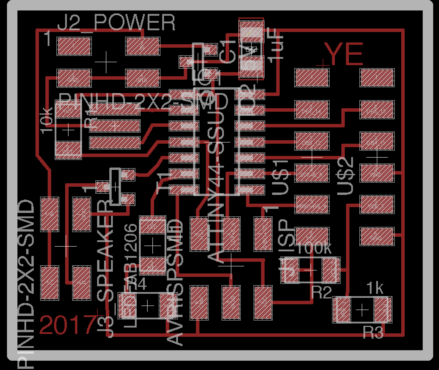
The design of my board
Since the Shih-Kuo Lin from Fablab Taipei came to our labs and worked together with the MTM assignment, so we have a discussion about the design of the board:
We deicided to make a board that can control a LCD, a LED and a speaker, so we make full used of the Pin in Attiny44.
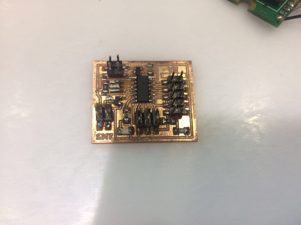
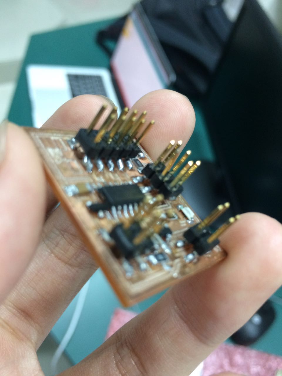
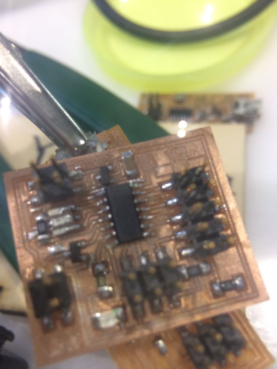
Here is what my board look like:
In my board, Pin9 - Pin13 are used to control the LCD, Pin 6 is used to control the LED, and Pin 5 is used to control the speaker.
To make sure the LED work normally, it should be linked to a 499R resistor.
Since the speakers in our lab need 5 voltage to power, I need to use a 5v IC2 on my board to make it work.
Then solider the component on it
The list of the materials that are needed:
1. 2*2 smd jack       --2
2. 2*3 smd jack       --1
3. Attiny 44          --1
4. LED                --1
5. 20 MHZ resonator   --1
6. Resistor : 100k*1 1k*1 10k*1
7. 1uf Capacity       --1
8. 2*5 smd jack       --1
9. IC2 5v             --1
preperation
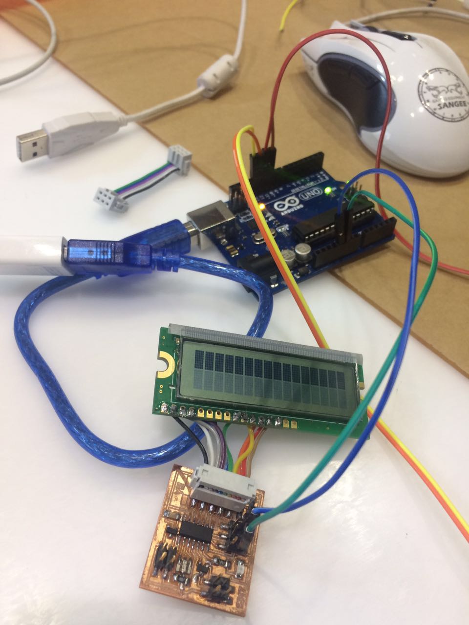
Since I can't find the arduino uno in our lab, I taked the advice from Shih-Kuo Lin that used the arduino uno as a ISP
Here is what he said:
1. burn the examples file - ArduinoISP - to the arduino uno
Then:
● ATTINY44 SCK Pin to Arduino Pin 13
● ATTINY44 MISO Pin to Arduino Pin 12
● ATTINY44 MOSI Pin to Arduino Pin 11
● ATTINY44 Reset Pin to Arduino Pin 10
I I found it work so I used the arduino uno to code my board.
2.LCD has 16 pins and each pin has specific function. I just follow the tutorial which described on the arduino website and The video of the LCD board in the schedule website.
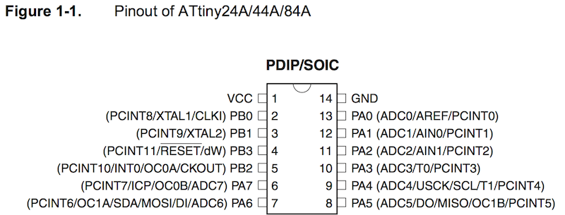
After reading the Attiny44 data sheet, I found: the pins connection between Attiny44 and LCD were as following :
PA0 -> LCD 14(DB7)
PA1 -> LCD 13(DB6)
PA2 -> LCD 12(DB5)
PA3 -> LCD 11(DB4)
PA4 -> LCD 6(Enable signal)
PA5 -> LCD 4(Register select)
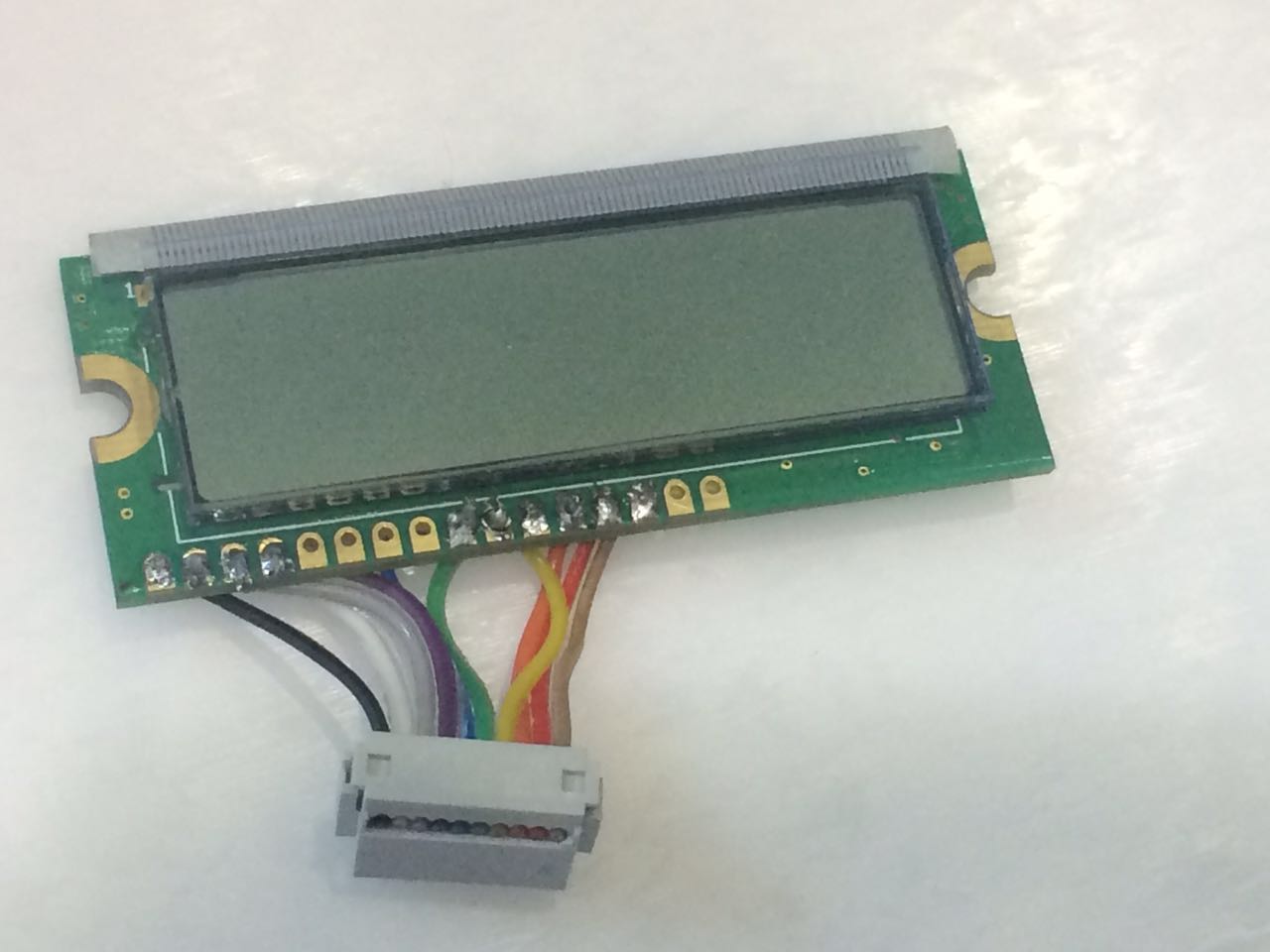
Here is the my LCD board:
The time you connect the board and the LCD to the arduino UNO and the computer/ any VCC you will find the LCD lights up:
what i code for my board
#define  c     3830    // 261 Hz
#define  d     3400    // 294 Hz
#define  e     3038    // 329 Hz
#define  f     2864    // 349 Hz
#define  g     2550    // 392 Hz
#define  a     2272    // 440 Hz
#define  b     2028    // 493 Hz
#define  C     1912    // 523 Hz
#define  R     0
#include <LiquidCrystal.h>
LiquidCrystal lcd(5,4,3,2,1,0);
int LEDPin = 7;
int speakerOut = 8;
int DEBUG = 1;
void setup()
{
  pinMode(LEDPin,OUTPUT);
  lcd.begin(16,2);
  lcd.setCursor(0,0);
  lcd.print("Ye Xiaohua");
  lcd.setCursor(0,1);
  lcd.print("FabAcademy2017");
   pinMode(speakerOut, OUTPUT);
}
int melody[] = {  C,  b,  g,  C,  b,   e,  R,  C,  c,  g, a, C };
int beats[]  = { 16, 16, 16,  8,  8,  16, 32, 16, 16, 16, 8, 8 };
int MAX_COUNT = sizeof(melody) / 2;
long tempo = 10000;
int pause = 1000;
int rest_count = 100;
int tone_ = 0;
int beat = 0;
long duration  = 0;
void playTone() {
  long elapsed_time = 0;
  if (tone_ > 0) {
    while (elapsed_time < duration) {
      digitalWrite(speakerOut,HIGH);
      delayMicroseconds(tone_ / 2);
      digitalWrite(speakerOut, LOW);
      delayMicroseconds(tone_ / 2);
      elapsed_time += (tone_);
    }
  }
  else { // Rest beat; loop times delay
    for (int j = 0; j < rest_count; j++) {
      delayMicroseconds(duration);
    }
  }
}
void loop() {
  for (int i=0; i<MAX_COUNT; i++) {
    tone_ = melody[i];
    beat = beats[i];
    duration = beat * tempo;
    playTone();
    digitalWrite(LEDPin,HIGH);
    delayMicroseconds(pause);
  }
  digitalWrite(LEDPin,LOW);
  delay(500);
}
Here is a short video of it:
problem and fix
1. After we finished the solid of the board, Shih-Kuo Lin started to test the speaker but failed many times. As a result, we scrutinized the files from the website about it and check the board between the schedule website and our eagle files.
Then we found out that we design the T1 components in a reverse direction.
As a result, we discussed and decided to resolid it by reversing its direction from the front to the back and fixed it.
The Eagle files above have already fixed this problem!
2. Then, we used the arduino examples: tone Melody() but the speaker still can't work
Shih-Kuo Lin and I find the information in the website from Arduino/Attiny44 data sheet/ MOSFET's data sheet. Then we knowed that it needs to use the PWM to control the speaker to play sound.
We read another arduino instruction from the website and let the speaker played the melody
Here is a short video of it: