~ Embedded programming.
~ post date: 2017.3.20, recent update: 2017.3.22
When you have a stuffed printed circuit board, it will do nothing until you program it. There are many programming languages available, all with their own quirks, advantages, barriers to entry, etc. Within the Fab Academy, Arduino IDE is the most widely used programming enviroment. The code is relatively easy to understand and widely supported and documented online. On the other end of the spectrum is C. C is one of the oldest programming langauges and is a bit daunting for a fledgling programmer. I rather enjoy programming (although I am only a beginner) and would like to learn a language beyond Arduino IDE but I think for the next few months, I will focus mostly on Arduino as it is a good gateway drug. In this post, I will explore programming in C and Arduino IDE.
Project files
Datasheet Atmel ATtiny24/44/84
Datasheets are hardcore product manuals for instructing makers on how to integrate specific products (ie electronic components) into systems. Datasheets are typically created by the product manufacturer and include technical and performative characteristics, connectivity information, coding examples, etc.
A datasheet for an electronic component, such as an MCU like the ATtiny44, typically contains the following:
- Feature list and overview
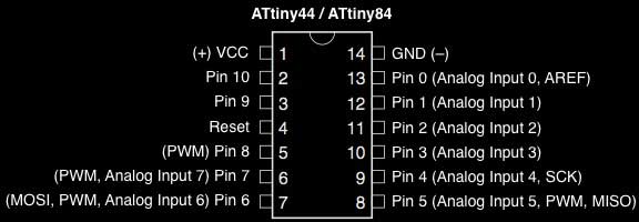
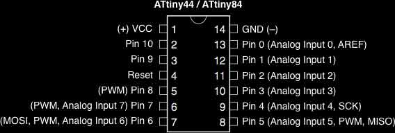
- Pin configurations and descriptions
- Timing diagrams
- Reset and interrupt handling
- Register description
- Memories details
- Input/output informations
- Clock system
- Power management
- Packaging details and configurations
- and much more!
This is the first time I have read a datasheet and I have only a handful of hours of experience working with electronic components physically and digitally. Following I pulled out some informations that grabbed my attention and diagrams. I like diagrams.
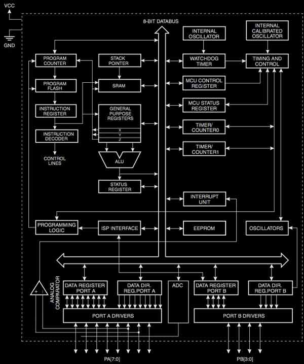
The ATtiny24A/44A/84A provides the following features: 2K/4K/8K byte of In-System Program- mable Flash, 128/256/512 bytes EEPROM, 128/256/512 bytes SRAM, 12 general purpose I/O lines, 32 general purpose working registers, an 8-bit Timer/Counter with two PWM channels, a 16-bit timer/counter with two PWM channels, Internal and External Interrupts, a 8-channel 10-bit ADC, programmable gain stage (1x, 20x) for 12 differential ADC channel pairs, a programmable Watchdog Timer with internal oscillator, internal calibrated oscillator, and four software select- able power saving modes. Idle mode stops the CPU while allowing the SRAM, Timer/Counter, ADC, Analog Comparator, and Interrupt system to continue functioning. ADC Noise Reduction mode minimizes switching noise during ADC conversions by stopping the CPU and all I/O mod- ules except the ADC. In Power-down mode registers keep their contents and all chip functions are disbaled until the next interrupt or hardware reset. In Standby mode, the crystal/resonator oscillator is running while the rest of the device is sleeping, allowing very fast start-up combined with low power consumption. -pg.5
ATtiny24A/44A/84A are low-power CMOS 8-bit microcontrollers based on the AVR enhanced RISC architecture. By executing powerful instructions in a single clock cycle, the ATtiny24A/44A/84A achieves throughputs approaching 1 MIPS per MHz allowing the system designer to optimize power consumption versus processing speed. -pg.4
The AVR core combines a rich instruction set with 32 general purpose working registers. All 32 registers are directly connected to the Arithmetic Logic Unit (ALU), allowing two independent registers to be accessed in one single instruction executed in one clock cycle. -pg.4
Block diagram:
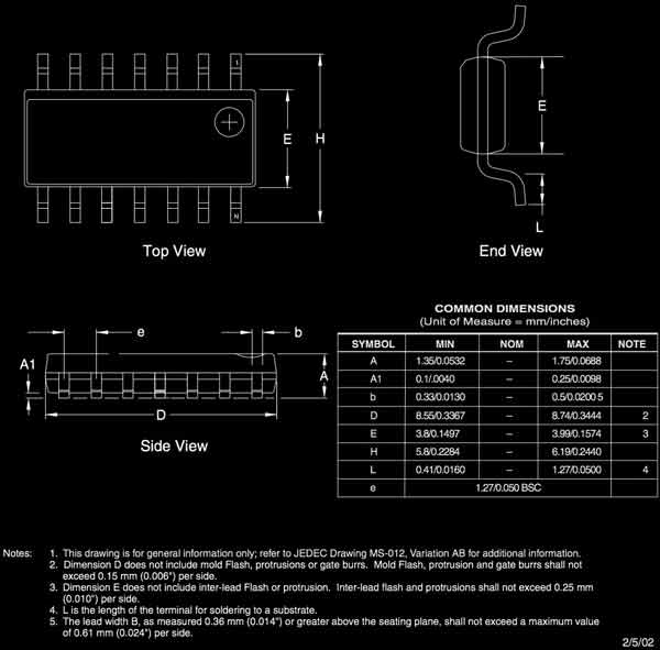
Packaging drawing:
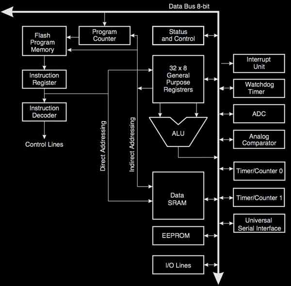
In order to maximize performance and parallelism, the AVR uses a Harvard architecture – with separate memories and buses for program and data.-pg.7
Block diagram of the AVR architecture:
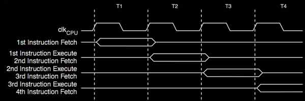
The parallel instruction fetches and instruction executions diagram:
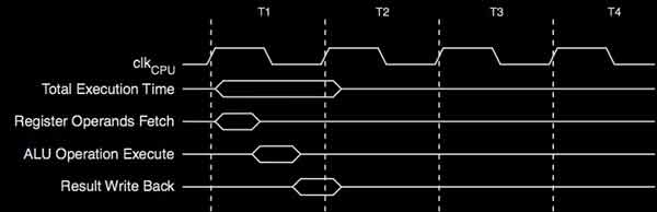
Single cycle ALU operation diagram:
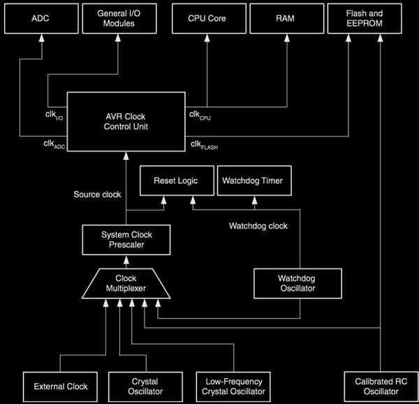
Clock distribution diagram:
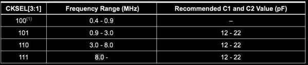
XTAL1 and XTAL2 are input and output, respectively, of an inverting amplifier which can be con- figured for use as an On-chip Oscillator. Either a quartz crystal or a ceramic resonator may be used. -pg.28
Crystal oscillator operating modes diagram:
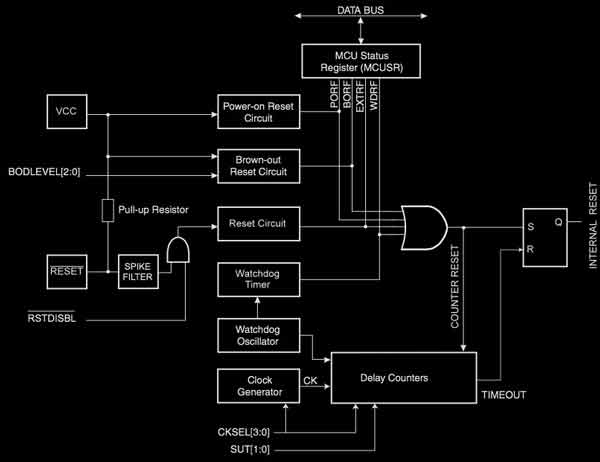
Reset logic diagram:
I will post links to resources I have found helpful here.
Arduino IDE 1.8.0
This is Arduino:
- a family of open-source, programmable Atmel microcontroller-based boards
- an abstraction on top of standard C syntax and libs
- a cross-platform IDE
- a bootloader that can upload code without a hardware programmer
- a micro-USB port to plug into the computer, digital/analog input/output pins, a separate power jack, an ISP header, and a reset button
For my purposes today, I will be using the Arduino IDE, an application written in Java in combination with my own fabbed TinyISP. In my limited experience, it is quite similar to Processing. (Unfortunately, I have forgotten everything else about Processing.) Programs may be written in any programming language for a compiler that produces binary machine code for the target processor (wikipedia).
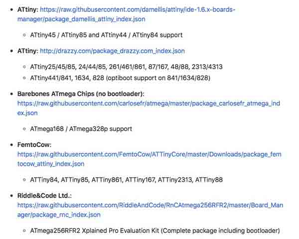
I will be using Arduino 1.8.0. You can find it online with something called google. If you are not using an Arduino AVR board, you will need to add support for non Arduino boards. Here is an unofficial list of 3rd party boards support urls github. You can start there. In my case, I am using my ATtiny44 board. Here is the appropriate URL (as of today):
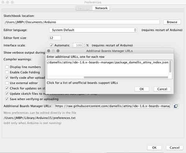
Copy the URL into the Arduino application's board manager. File>Preferences "Additional Boards Manager URLs".
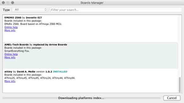
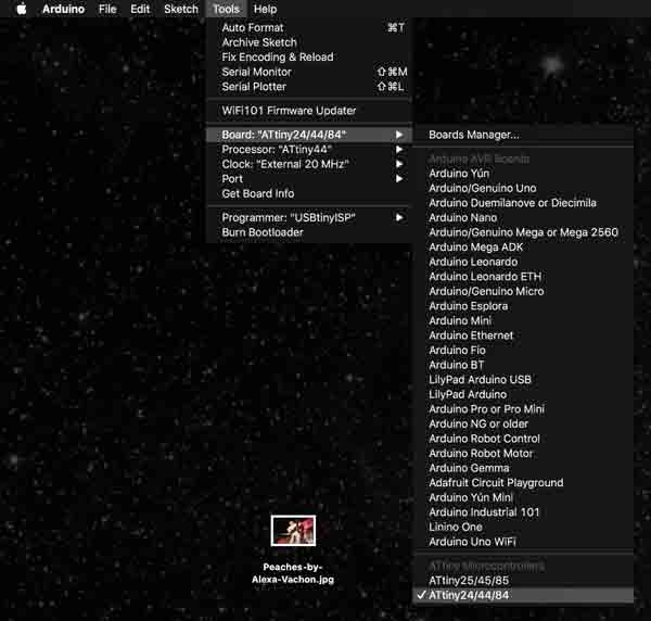
From Tools>Board>Boards Manager... Find the corresponding entry for the board you added and click the install button. Arduino will download the stuff it needs to work with your board.
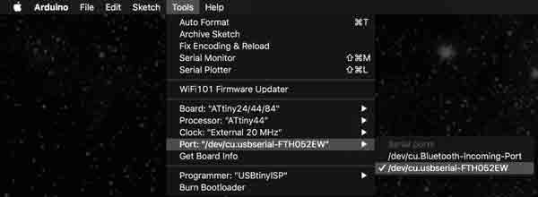
Then within the Tools menu, specify your board, processor, clock and programmer. For my board in the same order:
- ATtiny24/44/84
- ATtiny44
- External 20 MHz
- USBtinyISP
One last step before coding for your board. You will need to translate your microcontroller pin-outs to Arduino friendly speak. Google is your friend. For instance the ATtiny44 pin 6 needs to be designated as Pin 7 in Arduino. Pin 6 (Arduino 7) is the location of my LED and Pin 10 (Arduino 3) my switch.
According to High-Low Tech these Arduino commands are supported by the ATTiny44:
- pinMode()
- digitalWrite()
- digitalRead()
- analogRead()
- analogWrite()
- shiftOut()
- pulseIn()
- millis()
- micros()
- delay()
- delayMicroseconds()
- SoftwareSerial
The Arduino application is packaged with some simple example sketches which are great for a quick start with your board. Go to File>01.Basics>Blink
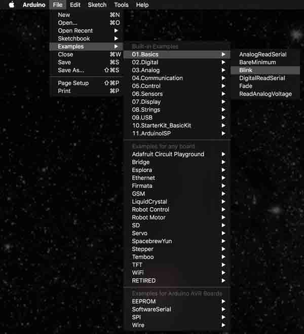
The programming window will open with Blink. Super!
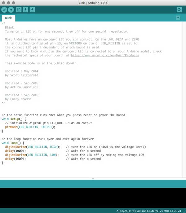
The setup function is called just once when the sketch is loaded and/ or after a restart or power-up (not the mushroom variety of power-ups). This area is for loading libraries, initializing variables, input and output pin modes, etc.
void setup() {
  pinMode(LED_BUILTIN, OUTPUT);
}
Following the setup, the loop is the main program which will run FOREVER. Or, until the board is reprogrammed or powered off. The program runs sequentially. First, the LED is turned on. Then the microcontroller is told to hold tight for a timed interval, here, one second. After, that interval, turn the LED off and wait another time interval. Repeat. That means, return to the first line of the loop, and work through the commands again. And again. Again. Again!
void loop() {
  digitalWrite(LED_BUILTIN, HIGH);
  delay(1000);
  digitalWrite(LED_BUILTIN, LOW);
  delay(1000);
}
One problem though, the "LED_BUILTIN" refers to an Arduino on-board LED, not my custom board. I need to specify my LED pin 6 (Arduino 7). I can do this by changing the three "LED_BUILTIN" locations to "7". Or, I could specify an integer, the primary data-type for number storage and change the "LED_BUILTIN" to my integer variable name. In this syntax, you can see the structure. "int" tells Arduino this is an integar. This needs to be written exactly as so. "var" is your integar variable name and "val" is the value you assign to this variable.
int var = val;
So in my case it will be written:
const int ledPin = 7;
I will write that somewhere above the void setup and then change "LED_BUILTIN" to "ledPin", my integar value. I added the "const" keyword, meaning constant, because this is an integar that never changes.
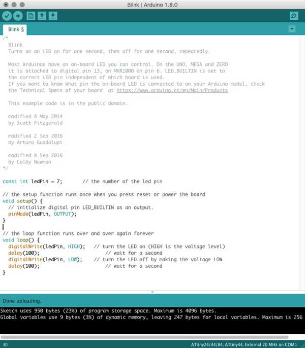
With the fabISP, the ATTiny44 board and your computer interconnected, press the arrow button to load the program to the ATTiny44. And, I have a blinking LED! Believe me, it is blinking. Wait for it.
Unfortunately, the LED is blinking on an estimated 8 second delay instead of the intended 1 second. Perhaps there is a necessary conversion for the 20MHz clock speed with the ATtiny44 using Arduino, my confusion over proper conversion of the delay(time) and 20MHz CPU speed, a calibration between the external resonator and the ATtiny44, or confusion with the clock speed / clock prescaler. I changed the delays to 100 and the LED began blinking at nearly one second on, one second off. I tried adding some code from the ATMEL datasheet (page 30) into my Arduino sketch to adjust the clock prescaler (haha): nothing. Shooting in the dark here.
const int ledPin = 7;

void setup() {
  pinMode(LED_BUILTIN, OUTPUT);
}

void loop() {
  digitalWrite(LED_BUILTIN, HIGH);
  delay(100);
  digitalWrite(LED_BUILTIN, LOW);
  delay(100);
}

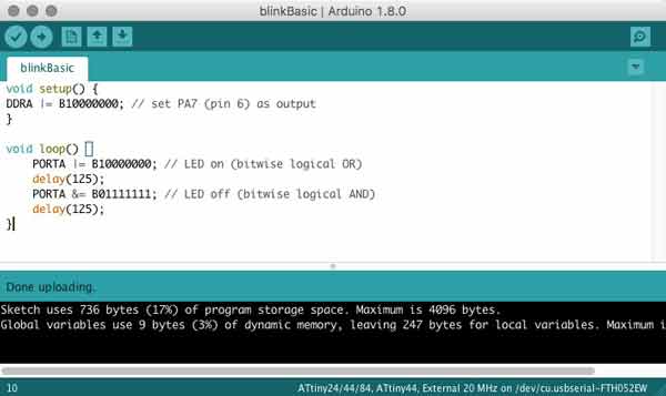
Thanks to Karsten Nebe, this code directly manipulates the registers and is more efficient. The delays set to 125 makes for 1 second blinky.
void setup() {
    DDRA |= B10000000; // set PA7 (pin 6) as output
}

void loop() {
    PORTA |= B10000000; // LED on (bitwise logical OR)
    delay(125);
    PORTA &= B01111111; // LED off (bitwise logical AND)
    delay(125);
}
I will post links to resources I have found helpful here.
Echo : Programming.c
I am testing the assembly of the board by attempting to program it.
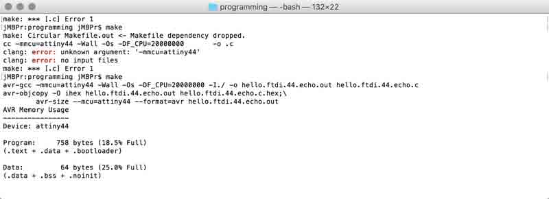
Start by downloading the Makefile and the echo hello-world C program written by Neil Gershenfeld. To make things simpler, rename the *.make file to simple "Makefile". No extension. In MacOS the best way to do this is in the file information dialogue. Open the Makefile with a neutral editor, such as Textedit to learn about its setup. The first group of lines refer to the project name, the source of the project (echo hello-world C program), the Micro-controller (ATtiny44), and the clock cycles 20mHz. All matching the electronic components on my board. The second half refers to the two HEX files that will be generated. "avr-gcc" is a programming language compatible with ATtinies.
PROJECT=hello.ftdi.44.echo
SOURCES=$(PROJECT).c
MMCU=attiny44
F_CPU = 20000000

CFLAGS=-mmcu=$(MMCU) -Wall -Os -DF_CPU=$(F_CPU)

$(PROJECT).hex: $(PROJECT).out
	avr-objcopy -O ihex $(PROJECT).out $(PROJECT).c.hex;\
	avr-size --mcu=$(MMCU) --format=avr $(PROJECT).out

$(PROJECT).out: $(SOURCES)
	avr-gcc $(CFLAGS) -I./ -o $(PROJECT).out $(SOURCES)
Several lines down in the file are the commands specific to my programmer: usbtiny.
program-usbtiny: $(PROJECT).hex
	avrdude -p t44 -P usb -c usbtiny -U flash:w:$(PROJECT).c.hex

program-usbtiny-fuses: $(PROJECT).hex
	avrdude -p t44 -P usb -c usbtiny -U lfuse:w:0x5E:m
Open terminal. Browse to the folder with the two files and enter one simple command.
make
Initially, the command did not operate because the Makefile was corrupted by Textedit in my process of fiddling. I deleted the Makefile and downloaded another copy and the commanded executed.
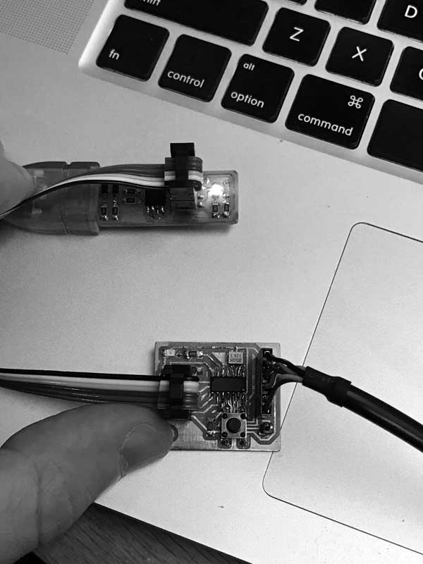
Now connect the boards to your computer. I connected the programmer I made previously to one USB port and the new board to my other via an FTDI to USB cable. The black wire aligns with the ground. Then with the grounds aligned (USB left), I can visualize how to properly connect my freshly fabbed ISP line.
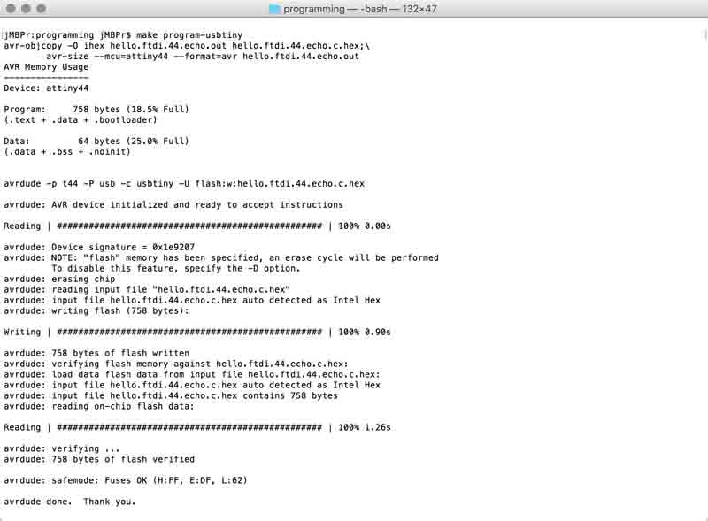
With the boards connected flash the program to the MCU:
make program-usbtiny
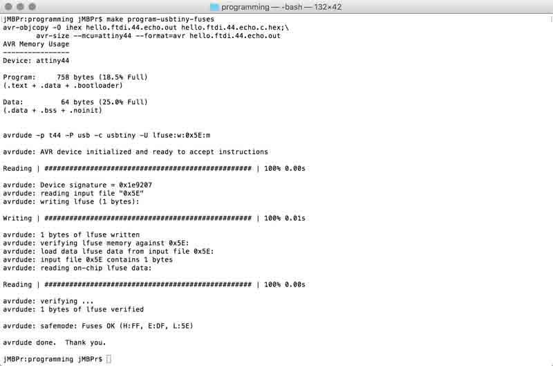
And set the configuration fuses:
make program-usbtiny-fuses
Now my board is recognized by my computer's USB drive. This next part was tricky because I did not know anything about serial monitors, much less python. Thankfully, where there are questions there is this. Ultimately, I was able to use Arduino and Python as serial monitors. I will explain both.
Python 2.7 is preloaded on MacOS yet needs to be extended with additional libraries for communicating with the serial port: Pyserial. Go there and download the appropriate installation files. Unzip. Direct terminal to the unzipped folder.
python setup.py install
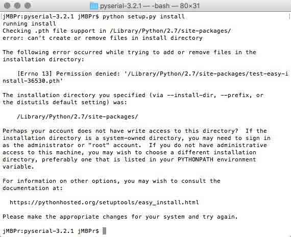
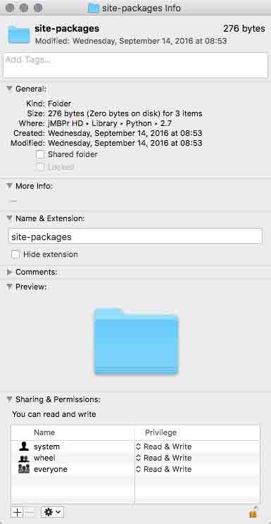
The Python folders on my computer were set to prevent me from making changes... MY COMPUTER! I took the shortcut of temporarily changing two folders' permissions:
/Library/Python/2.7/site-packages/
/usr/local/bin/
With that change, the installation was successful. Copy: rx.py and term.py into your working directory. With your board connected via FTDI, you need to find its serial port. Use a list command. /dev/tty stands for the "controlling terminal for the current process." Okay, well, I have to keep moving.
ls /dev/tty.*
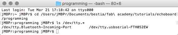
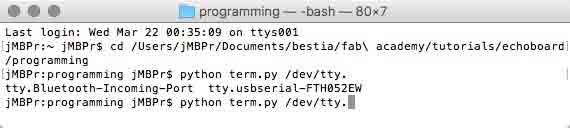
I am looking for the USB->FTDI cable. Fortunately, this is self-evident. Finally, you need to launch a python comm window with the programmed echo board. Issue a python command. Use term.py (which calls on a serial library installed previously). Point it at your FTDI connected device. Set the BAUD rate to 115200.
python term.py /dev/tty.usbserial-FTH052EW 115200
Another technique is to type up to the "...tty." then press TAB. A list of available serial ports will be listed. Copy/paste the correct one and end the command with the BAUD rate.
If all is correct, this window might open. Click somewhere in the window and press a key. You will not see any recognition of your key press within the window but your board should respond with the key you pressed. For some reason, I am receiving some odd inconsistencies: the name of the board is returned in variations, sometimes key cases are changed, and sometimes the space bar does not return a space. Also, when I try to quit the window, it stalls until I disconnect the FTDI cable. Still, it is mostly working.
Alternatively, Arduino can be used as a serial monitor and it was a much easier setup. Ensure the Python serial monitor is disconnected (and vice versa) or it may cause problems for you. Browse to Tools>Port> and select your FTDI connection. Incidentally, this is a workable alternative to the ls terminal command. The address is slightly different but still operational. I know, I tested it.
Return to the Tools menu and select "Serial Monitor". Type characters and press send. One at a time. Hello world.
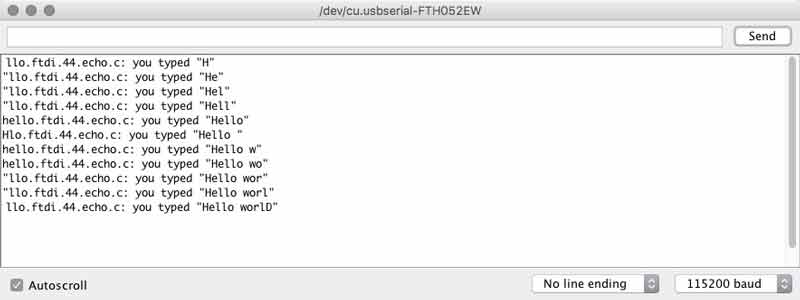
I have found that garbled text sometimes is associated with mismatched BAUD rates so I tested this with different rates. The text became symbols.
I will post links to resources I have found helpful here.
Breathing light : An arduino experiment
I now have a grasp of making slight adjustments to code and uploading code to my board. Now that I have a little taste, I want more, so I imagined a simple idea to go a step beyond the tutorials and example codes. An interesting thing to me about coding is how the process is not linear, like what can often happen in other design fields. I can start layering in code and then make a little game of optimizing that code for editing, total number of executions, or number of lines, for instance. In fact, speaking of games, I am a fan. And there are many games available online for learning code in many different languages. Although I did not have much time to explore them all, I will probably come back to some in my free time. One multiplatform (including iOS) game: Human Resource Machine helped prime my brain for thinking code. The diffculty ramps up nicely (which translates into increasingly challenging coding) and it was fun!
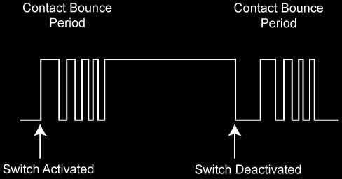
Next, I dove into this tutorial to learn about using a switch, which was absent up to this point, Pulse Width Modulation (PWM) and compensating for switch bouncing (more on these later).
When the button is pressed, there may be some bouncing that occurs within. These are tiny parts and the bouncing may only occur over fractions of a second. To the MCU, however, that might be what we perceive as days. This diagram shows the effect. Your code can include a configurable delay in reading the switch to bypass the bouncing period after pressing it.
From Arduino: "Pulse Width Modulation, or PWM, is a technique for getting analog results with digital means. Digital control is used to create a square wave, a signal switched between on and off." I went back to the ATtiny datasheet and sure enough, Pin 6, the location of my LED, has PWM.
I started by following along with the tutorial with some small mods. I think it is good to get a sense of how my process of building a code happens, so I will show some steps. Not interested? Skip to the bottom of this section. This first sketch turns on the LED when the switch is engaged and off when it is released.
const int switchPin = 3;
const int ledPin = 7;

void setup() {
  pinMode(switchPin, INPUT);
  pinMode(ledPin, OUTPUT);
}

void loop() {
  if (digitalRead(switchPin) == HIGH)
  {
    digitalWrite(ledPin, HIGH);
  }
  else
  {
    digitalWrite(ledPin, LOW);
  }
}
The next iteration changed the action to flipping the LED on and off with button presses, like a light switch. Here, you can see a couple of booleans are added. A boolean holds one of two values, ie. true or false. In the loop, if the switch is pressed which is verfied against the previous switch state, then flip the ledState (this is the function of the ! mark) and then change the lastSwitch back to high to reset the conditions for the if / else statement. And write the change to the ledState, change it to true for on, false for off.
const int switchPin = 3;
const int ledPin = 7;
boolean lastSwitch = LOW;
boolean ledState = false;

void setup() {
  pinMode(switchPin, INPUT);
  pinMode(ledPin, OUTPUT);
}

void loop() {
  if (digitalRead(switchPin) == HIGH && lastSwitch == LOW)
  {
    ledState = !ledState;
    lastSwitch = HIGH;
  }
  else
  {
    lastSwitch = digitalRead(switchPin);
  }
  digitalWrite(ledPin, ledState);
}
This iteration adds a debounce boolean to negate signal noise in the button presses. Basically, if the button state seems to change, wait a moment and verify the change. Adjust the delay according to its effectiveness. Then the loop incorporates the debounce boolean.
const int switchPin = 3;
const int ledPin = 7;
boolean lastSwitch = LOW;
boolean currentSwitch = LOW;
boolean ledState = false;

void setup() {
  pinMode(switchPin, INPUT);
  pinMode(ledPin, OUTPUT);
}

boolean debounce(boolean last)
{
  boolean current = digitalRead(switchPin);
  if (last != current)
  {
    delay(5);
    current = digitalRead(switchPin);
  }
  return current;
}

void loop() {
  currentSwitch = debounce(lastSwitch);
  if (lastSwitch == LOW && currentSwitch == HIGH)
  {
    ledState = !ledState;
  }
    lastSwitch = currentSwitch;
  digitalWrite(ledPin, ledState);
}
This version drops the ledState boolean, for an analog brightness. Everytime the button is pressed, the brightness of the light increases slightly. Until, that brightness number exceeds 255, when it is set back to 0 (off). That is the PWM at work.
const int switchPin = 3;
const int ledPin = 7;
boolean lastSwitch = LOW;
boolean currentSwitch = LOW;
int ledLevel = 0;

void setup() {
  pinMode(switchPin, INPUT);
  pinMode(ledPin, OUTPUT);
}

boolean debounce(boolean last)
{
  boolean current = digitalRead(switchPin);
  if (last != current)
  {
    delay(5);
    current = digitalRead(switchPin);
  }
  return current;
}

void loop() {
  currentSwitch = debounce(lastSwitch);
  if (lastSwitch == LOW && currentSwitch == HIGH)
  {
    ledLevel = ledLevel + 51;
  }
    lastSwitch = currentSwitch;

    if (ledLevel > 255) ledLevel = 0;
  analogWrite(ledPin, ledLevel);
}
I started trying to get the light to go through a series of brightness changes each time the button was pressed (rather than one change per press, several changes per press). After some trial and error, I moved the analogWrite function into the if statement, added some delays and went to work. This time with each button press the light turns off and then slowly increases in brightness up to full brightness and remains on.
const int switchPin = 3;
const int ledPin = 7;
boolean lastSwitch = LOW;
boolean currentSwitch = LOW;
int ledLevel = 0;

void setup() {
  pinMode(switchPin, INPUT);
  pinMode(ledPin, OUTPUT);
}

boolean debounce(boolean last)
{
  boolean current = digitalRead(switchPin);
  if (last != current)
  {
    delay(5);
    current = digitalRead(switchPin);
  }
  return current;
}

void loop() {
  currentSwitch = debounce(lastSwitch);
  if (lastSwitch == LOW && currentSwitch == HIGH)
  {
    ledLevel = 0;
    analogWrite(ledPin, ledLevel);
    delay(125);
    ledLevel = ledLevel + 51;
    analogWrite(ledPin, ledLevel);
    delay(125);
    ledLevel = ledLevel + 51;
    analogWrite(ledPin, ledLevel);
    delay(125);
    ledLevel = ledLevel + 51;
    analogWrite(ledPin, ledLevel);
    delay(125);
    ledLevel = ledLevel + 51;
    analogWrite(ledPin, ledLevel);
    delay(125);
    ledLevel = ledLevel + 51;
    analogWrite(ledPin, ledLevel);
  }
    lastSwitch = currentSwitch;

    if (ledLevel > 255) ledLevel = 0;
}
Next, I tried to get the light to increase in brightness from an off state to a full state and then back down. I added some variables for the brightness step and timer. Still, if I want to make any changes its a lot of work...
const int switchPin = 3;
const int ledPin = 7;
boolean lastSwitch = LOW;
boolean currentSwitch = LOW;
int ledLevel = 0;
int timer = 125;
int ledChange = 51;

void setup() {
  pinMode(switchPin, INPUT);
  pinMode(ledPin, OUTPUT);
}

boolean debounce(boolean last)
{
  boolean current = digitalRead(switchPin);
  if (last != current)
  {
    delay(5);
    current = digitalRead(switchPin);
  }
  return current;
}

void loop() {
  currentSwitch = debounce(lastSwitch);
  if (lastSwitch == LOW && currentSwitch == HIGH)
  {
    ledLevel = ledLevel + ledChange;
    analogWrite(ledPin, ledLevel);
    delay(timer);
    ledLevel = ledLevel + ledChange;
    analogWrite(ledPin, ledLevel);
    delay(timer);
    ledLevel = ledLevel + ledChange;
    analogWrite(ledPin, ledLevel);
    delay(timer);
    ledLevel = ledLevel + ledChange;
    analogWrite(ledPin, ledLevel);
    delay(timer);
    ledLevel = ledLevel + ledChange;
    analogWrite(ledPin, ledLevel);
    delay(timer);
    ledLevel = ledLevel - ledChange;
    analogWrite(ledPin, ledLevel);
    delay(timer);
    ledLevel = ledLevel - ledChange;
    analogWrite(ledPin, ledLevel);
    delay(timer);
    ledLevel = ledLevel - ledChange;
    analogWrite(ledPin, ledLevel);
    delay(timer);
    ledLevel = ledLevel - ledChange;
    analogWrite(ledPin, ledLevel);
    delay(timer);
    ledLevel = ledLevel - ledChange;
    analogWrite(ledPin, ledLevel);
  }
    lastSwitch = currentSwitch;
}
So I started to look around for a (my words) repeat something until something command. For that, I found the while statement. While the light is powered lower than my ledMax integar, add power at my timing. Once the ledMax is surpassed, reduce the power to zero at my timing. It is more convenient for me to ask the chip to find its own ledMax based on the ledChange interval. It mostly works, but sometimes the light flickers at its brightest.
const int switchPin = 3;
const int ledPin = 7;
boolean lastSwitch = LOW;
boolean currentSwitch = LOW;
int ledLevel = 0;
int timer = 25;
int ledChange = 5;
int ledMax = 0;

void setup() {
  pinMode(switchPin, INPUT);
  pinMode(ledPin, OUTPUT);
  while(ledMax <= 255) {
     ledMax = ledMax + ledChange;
  }
}

boolean debounce(boolean last)
{
  boolean current = digitalRead(switchPin);
  if (last != current)
  {
    delay(5);
    current = digitalRead(switchPin);
  }
  return current;
}

void loop() {
  currentSwitch = debounce(lastSwitch);
  if (lastSwitch == LOW && currentSwitch == HIGH)
  {
    while(ledLevel < ledMax) {
    ledLevel = ledLevel + ledChange;
    analogWrite(ledPin, ledLevel);
    delay(timer);
    }
    while(ledLevel > 0) {
    ledLevel = ledLevel - ledChange;
    analogWrite(ledPin, ledLevel);
    delay(timer);
    }
  }
    lastSwitch = currentSwitch;
}
Because, I was using poor math. I made some adjustments to the ledMax integar and it seems to be working now. Press the switch, and the light ramps up and ramps back down according to a specified timing and change interval.
const int switchPin = 3;
const int ledPin = 7;
boolean lastSwitch = LOW;
boolean currentSwitch = LOW;
int ledLevel = 0;
int timer = 50;
int ledChange = 25;
int ledMax = 0;

void setup() {
  pinMode(switchPin, INPUT);
  pinMode(ledPin, OUTPUT);
  while(ledMax < 255) {
     ledMax = ledMax + ledChange;
  }
  ledMax = ledMax -ledChange - 1;
}

boolean debounce(boolean last)
{
  boolean current = digitalRead(switchPin);
  if (last != current)
  {
    delay(5);
    current = digitalRead(switchPin);
  }
  return current;
}

void loop() {
  currentSwitch = debounce(lastSwitch);
  if (lastSwitch == LOW && currentSwitch == HIGH)
  {
    while(ledLevel < ledMax) {
    ledLevel = ledLevel + ledChange;
    analogWrite(ledPin, ledLevel);
    delay(timer);
    }
    while(ledLevel > 0) {
    ledLevel = ledLevel - ledChange;
    analogWrite(ledPin, ledLevel);
    delay(timer);
    }
  }
    lastSwitch = currentSwitch;
}
Then for fun, I removed the switch functionality completely for a more lifelike blinking sketch.
const int ledPin = 7;
int ledLevel = 0;
int timer = 50;
int ledChange = 25;
int ledMax = 0;


void setup() {
  pinMode(ledPin, OUTPUT);
  while(ledMax < 255) {
     ledMax = ledMax + ledChange;
  }
  ledMax = ledMax -ledChange - 1;
}

void loop() {
    while(ledLevel < ledMax) {
    ledLevel = ledLevel + ledChange;
    analogWrite(ledPin, ledLevel);
    delay(timer);
    }
    while(ledLevel > 0) {
    ledLevel = ledLevel - ledChange;
    analogWrite(ledPin, ledLevel);
    delay(timer);
    }
}
It could be fun to see if I can make the breathing like function turn on with the switch and off without and/ or to add some math induced variables to the change and timing intervals to make it even more wild.
Download project files
I will post links to resources I have found helpful here.
Jump : Index
J.travis Russett © 2017
 All the work contained within is licensed under a Creative Commons Attribution-NonCommercial-ShareAlike 4.0 International (CC BY-NC-SA 4.0) License
You may remix, tweak, and build upon my work non-commercially, as long as you credit me and license your new creations under the identical terms.