Week 16 May 10th: Networking and Communications
Wired and wireless communication between your projects
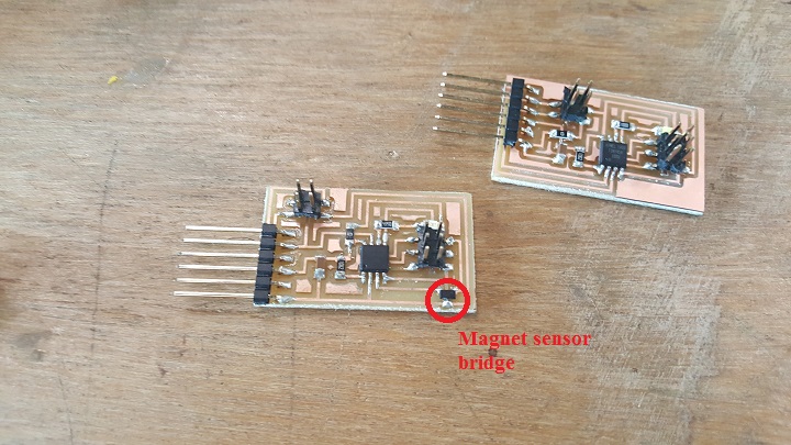
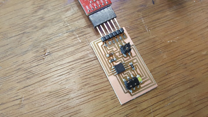
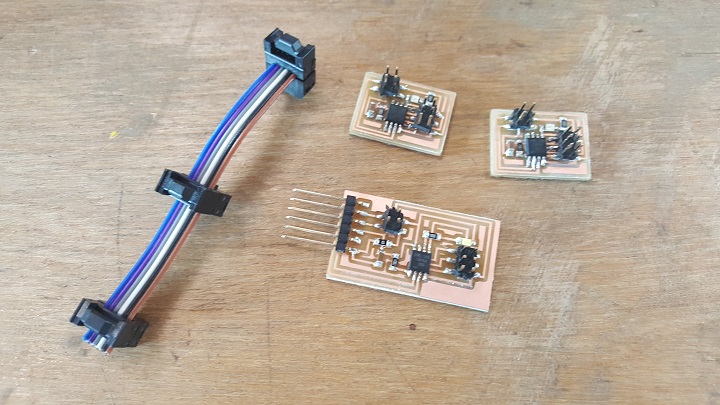
As I had to go on a 2.5 week trip to Shanghai next week(see you soon FabLab O and XinFabLab), I had to start doing my project beforehand. I started this week with plans to make a wired 2 node system that connects to my input magnetic sensor and then another wireless one using Edu's recommendation for a radio transmitter/reciever. I followed the directions on the archive website and built two nodes in record time, with one having a blue LED(node 2) and the other with an red LED(node 1). For the bridge(node 0), I fixed my previous magnet sensor board and also added a 2x2 joint for a dedicated port connecting to the nodes. And then I realized this is a lot harder than I thought because I was using two of the exisiting ports for the mag sensor so I didn't even connect the RX and TX to the ATTiny 45. Running out of time I compromised and built a simpler bridge, I just had to make a new bridge from the original magnet sensor file and connected the traces to make it work connected, and once I'm back from Shanghai I can continue making a wireless one with the magnet sensor integrated to it.
I got the code for the node "hello.bus.45.c" from the archive site and then switched the value in the line define node_id '#' to define each node as 0, 1, 2 and give them unique identifying IDs. After that I used Neil's test term.py file and ran it in terminal to get an interface and tested to see if the basic network system worked. I also edited the node in different ways such as sequenced lights for the LEDs and showing different output Print commands when you were pressing the button vs not pressing the button.
Using Arduino's serial monitor, I can input values and the nodes will flash the LEDs, resulting in a successful commmunication between the boards.
Design files Download .rar file