For this week, the assignments to be accomplish are:
Test the design rules for your printer
Design and 3D print an object (small, few cm) that could not be made subtractively
3D scan an object (and optionally print it)e
learn something new
1. TESTING THE PRINTERS
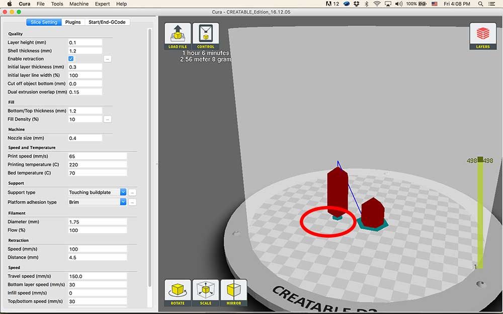
First, The 3D printer used for this week is a Korean brand Creatable D3 Delta bowden extruder with a maximun temperature of 240 (dont recommend ABS on it), using a CURA slicer (another important thing about this week is temperature fluctuations very high due to the old building and winter conditions) .I printed PLA using no support neither adhesion type, layer height 0.1mm shell/top/bottom thickness as 0.8mm and speed at 80 and temperature of 225 for the nozzle and 75 for the bed( before any comments our lab is located in a very old building where the difference in temperature during the day and night are very high)
I wanted know how well our printers were working so, I got a free stl from thingverse and journey started. For better understanding look for "ultimaker troubleshooting guide" on google.
I found several problems with the printers, first was adhesion to the plate ending up in warping(low temperature in the room might have affected), shifted layers due to the belts tension.
the picture on the right shows clearly that the first layer was not done correct therefore everything elase above that was influence by this.
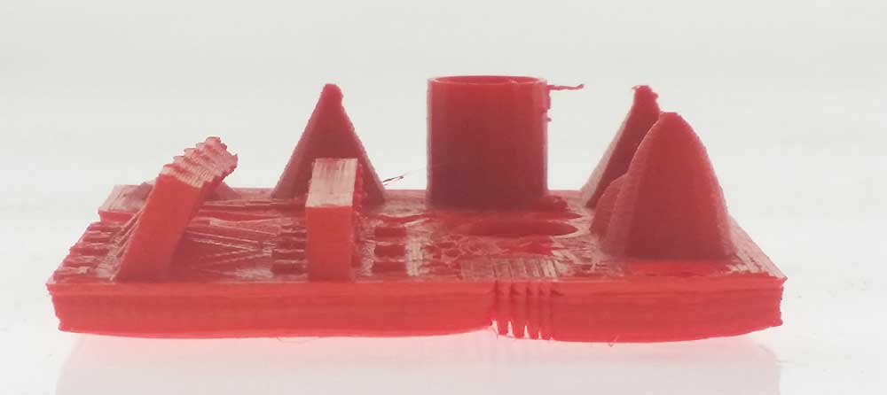
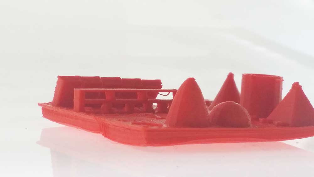
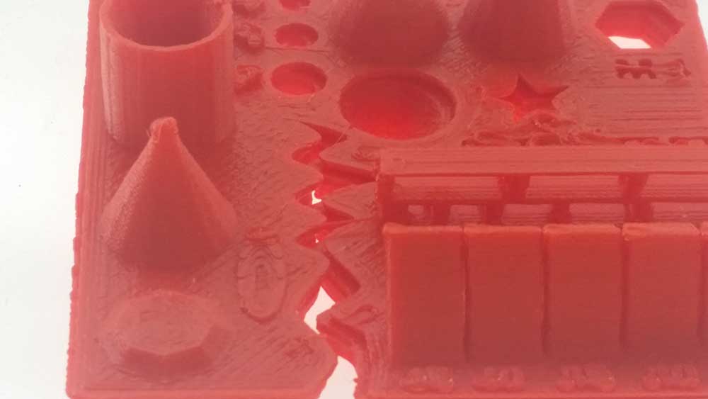
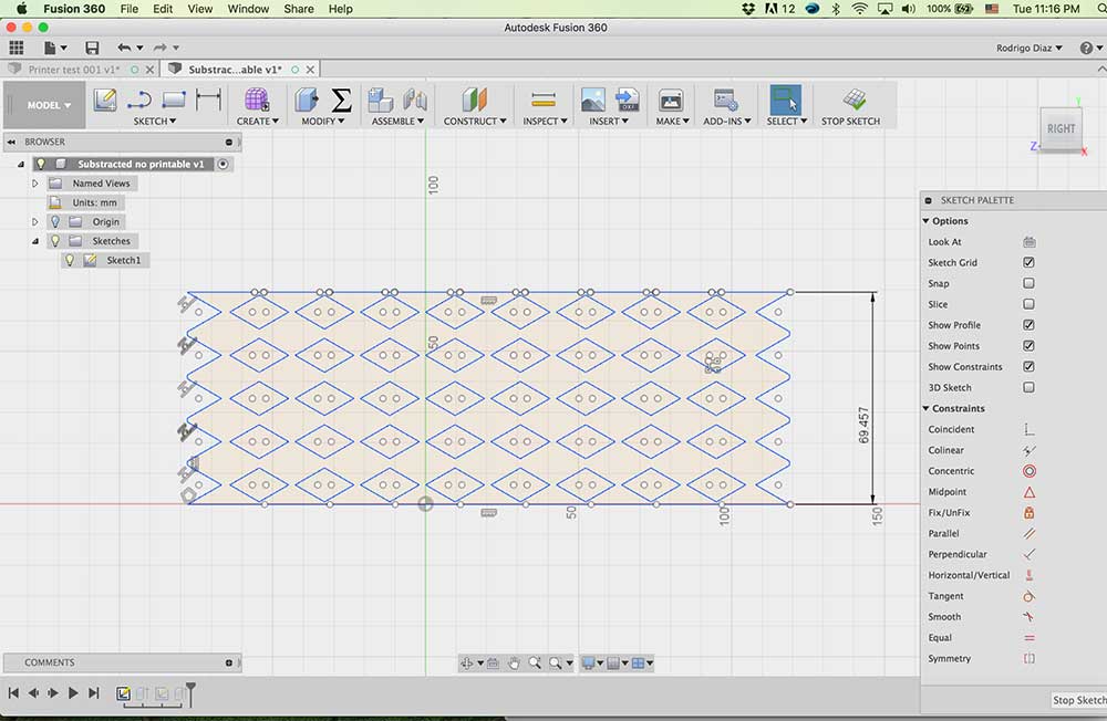
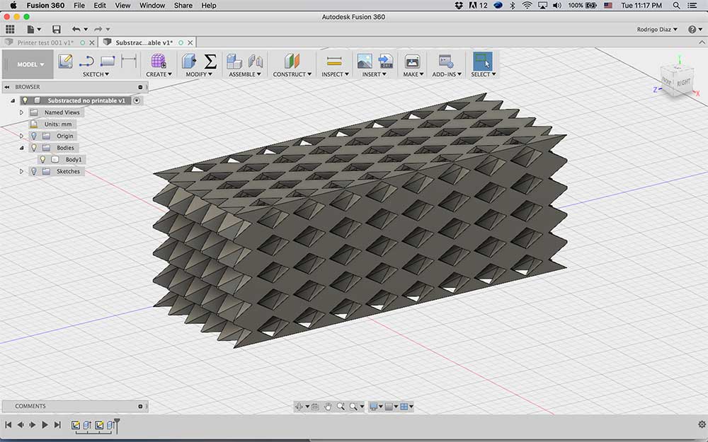
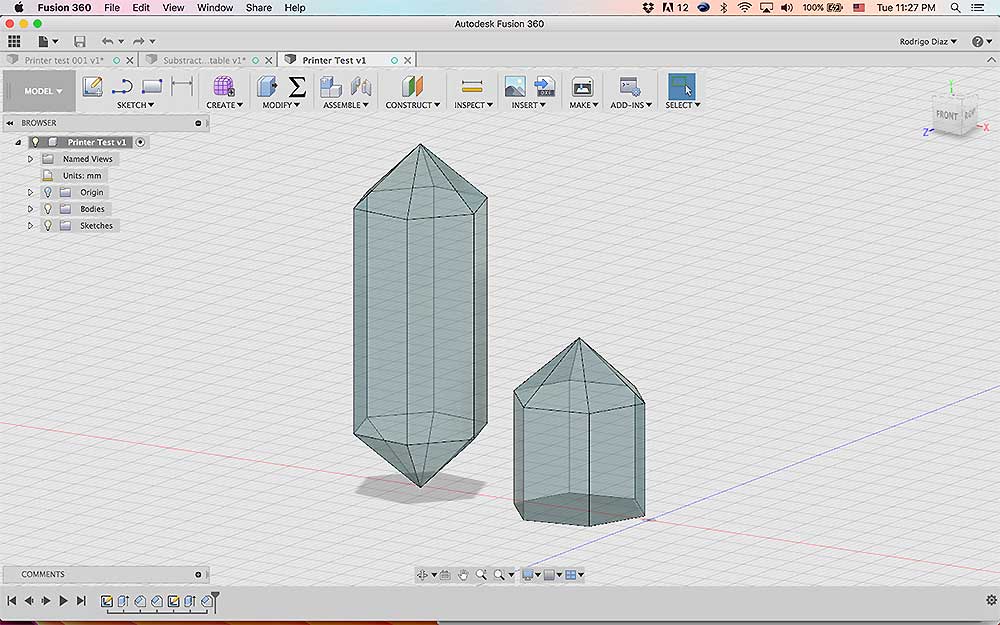
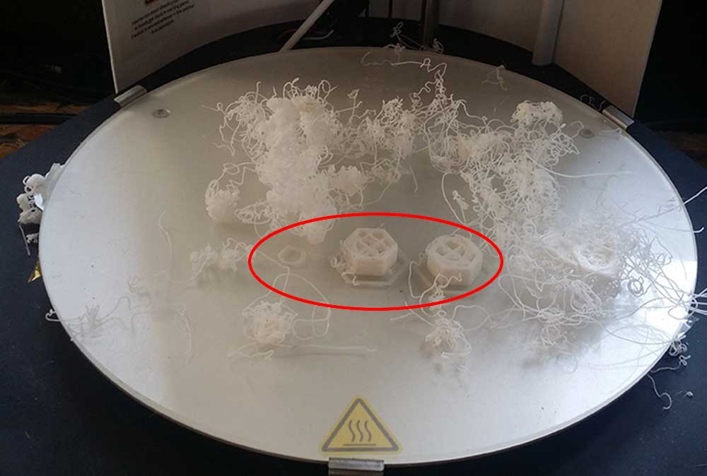
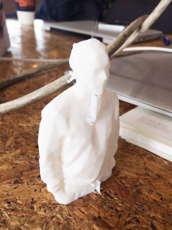
The file above was borrow from thingverse.com and as you see was a disarter. so maybe I need to create a file that will give me a simple and faster feedback regarding one characteristics of the printer.
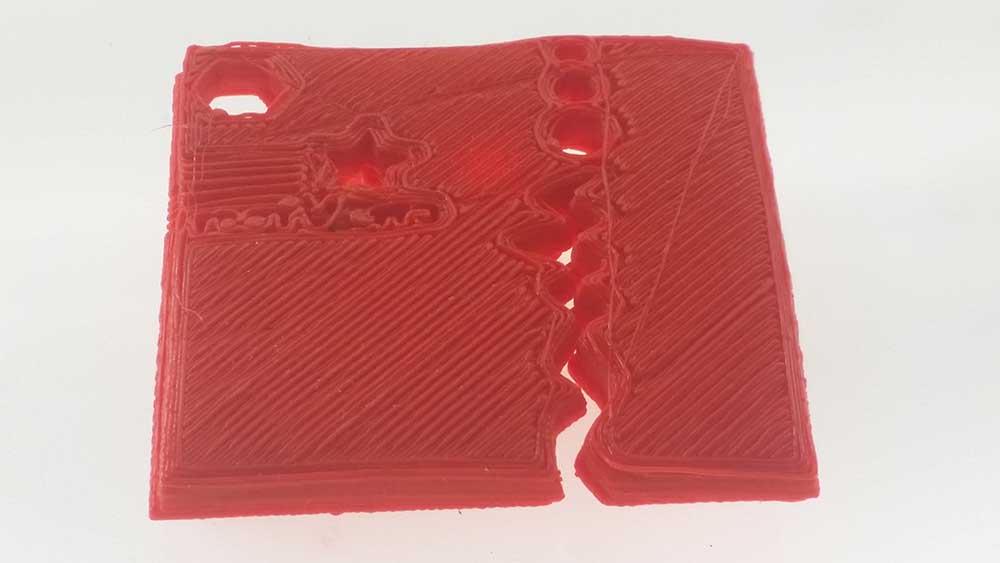
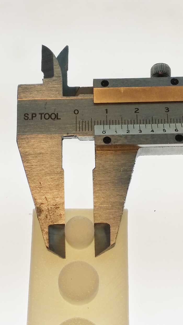
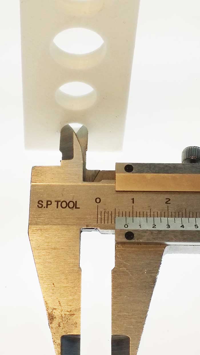
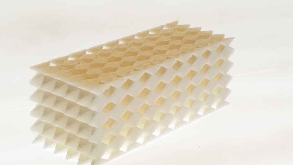
therefore, I end up doing is a file that can measure the constraction after the print is done.
Using Fusion 360 I created a file to check how much the print would shrink compare to the values that I gave it during CAD. beign totally honest, I have no idea what happend here. According to my drawing on top the small circle should be 15mm wide (check my units and values in Fusion and everything looks fine) the circle that supose to be 15mm is only 9mm mesured by the caliper. oh~ poopoo!! I just remeber that I might have scale it down to cut the printing time. just by comparing the differences betweeen the calipers number in only 1mm difference; However, I need to find out what happend with the difference between the drawing and the actual print... (6 months later) after checking the file I think that the drawing were not accurate (untill that time I had only 4 weeks using FUSION360) also, I think that for checking the calibration of the printers is not good to change the scale of the actual file.
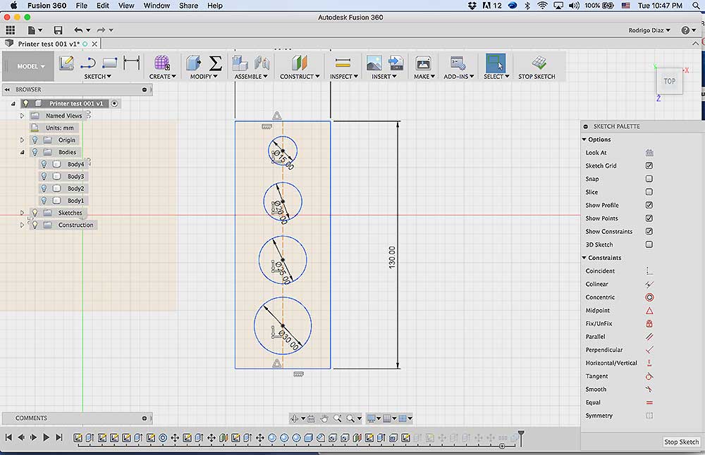
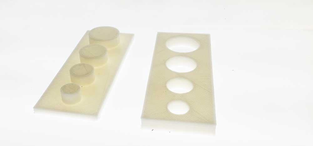
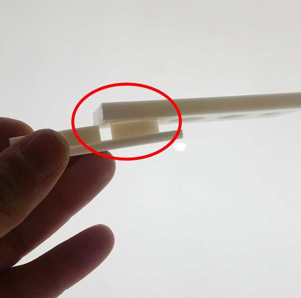
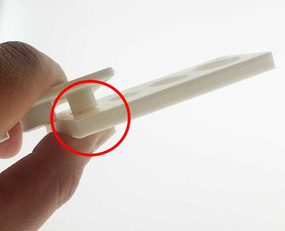
I wanted to take advantage of the 3D printing since If this model would have been made in a CNC it need to be rotate 6 time top/bottom wich has hangging part that are and 4 sides, this can only be made rotating too manny times and probably lose the orientation and failed. another solution is buy an 6axis CNC that cost at least 2 FabLabs (hahahaha)
I was thinking in the limitations and advantages of the 3D printer, once I realize that the print might take more than 6 hours I just finish it as soon as I could.
since was 3D printing week I tried printing an object with little support and as I expected was too small for an FDM type printer.
I tried printing the diamond as I made them (no brim or raft) just to check since the printer was showing that it could. And as expected PLA spaguetti was made instead.
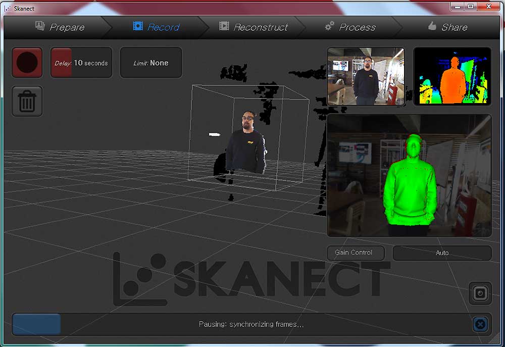
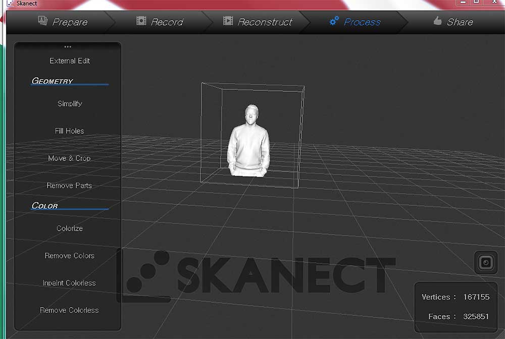
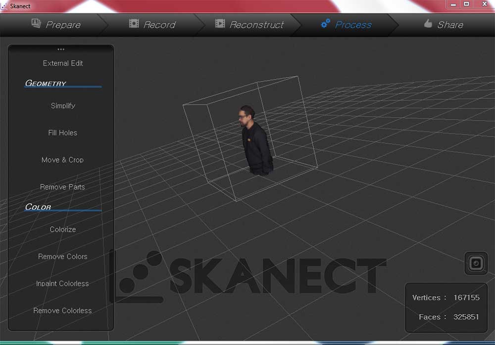
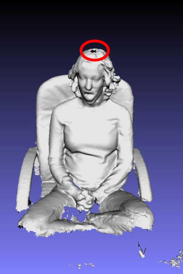
For the scanning assigment I used the KINECT that uses an RGB camera with depth sensor and infrared projector with a monochrome CMOS sensor which sees the environment not as a flat image, but as dots arranged in a 3D environment, the video below help me to understand more.
So, Actually Kinect needs two eyes just like us to determine the distance of an object, also researching about this topic I found out that to determine the distance of a star is done in a similar way by using two telecopes with 2 different angles (super cool right?)
From the help of Kurina (another FabAcademy Student) I scanned myself. I try to avoid any posture that might be difficult to scan; for example, arm cross or hands up where Kinect would be difficult to reach.
the Picture in the left show few areas were I am beign scann, first me in the center of a square (this represents the area that will be process to create the mesh, you can change the size of this square in the settings in the "prepare" tab).
seconds, In the top right you can see two screens. to the left is the normal camera view and to the right (red person green backroung) using the distance sensor that was explained in the video above.
The third box or green person is me becoming "HULK" (joke), green color in skannet represent a safe distance when scanning, red too close and blueish went you get further away from the object. In this case is all green because I finish scanning myself, you also can see in the botton the blue bar loading (processing image).
After I took my model to Meshmixers to clean up the model; however, it was pretty clean already and just by sending the file to the "inspector" options one click repare all did not break my model. (is what happend last time I tried) Usually the scan that I did before came with all kind of black holes (picture on the left) in the model and you needed to close them using Meshmixer. I thing that the model better done that I had expected.