Electronic Design. Let's start and say HELLO
Assignment
Redraw the echo hello-world board, add (at least) a button and LED (with current-limiting resistor) check the design rules, make it, and test it
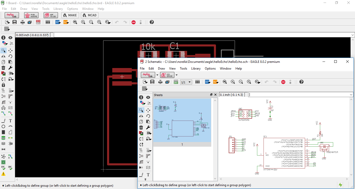
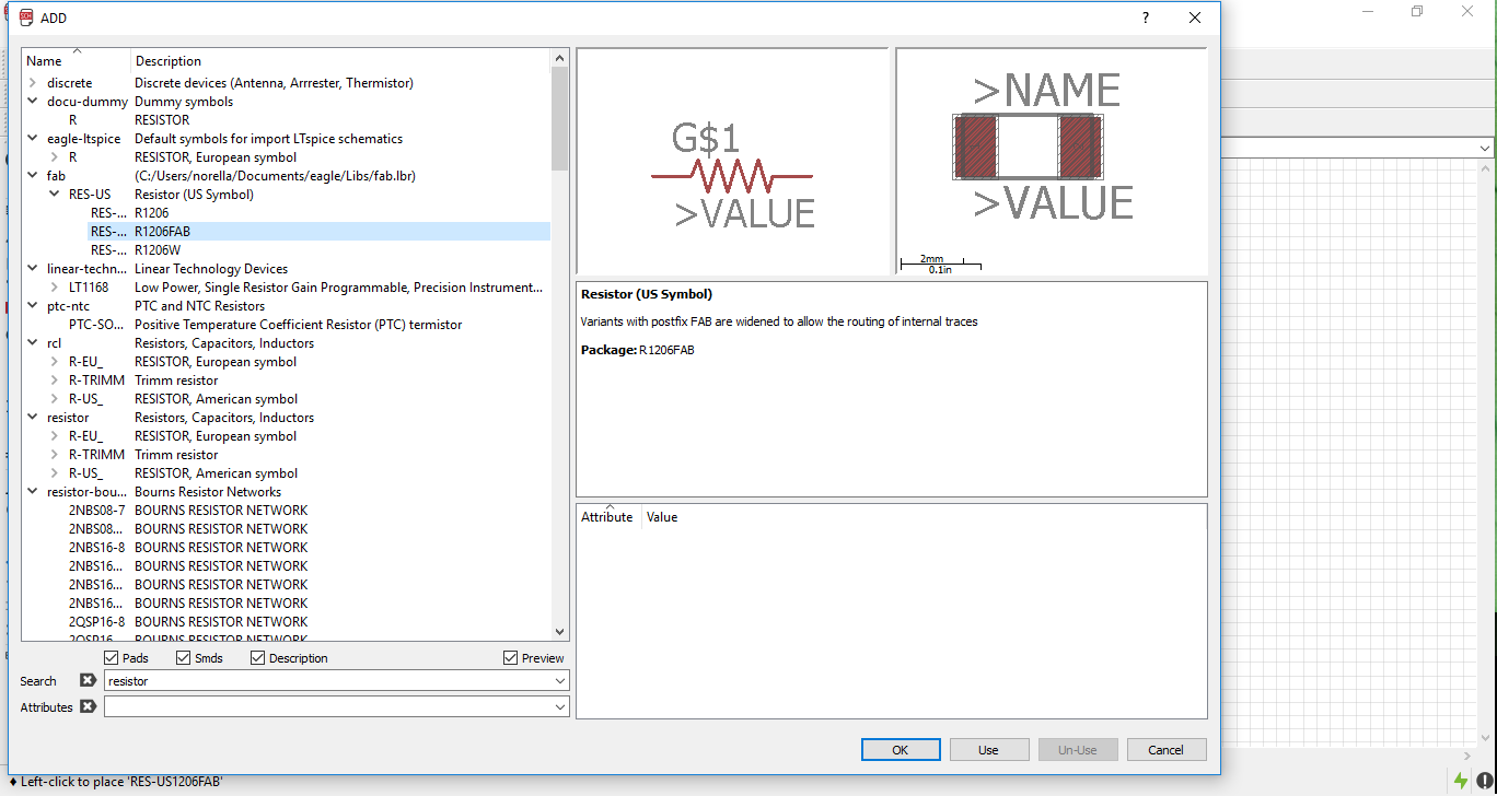
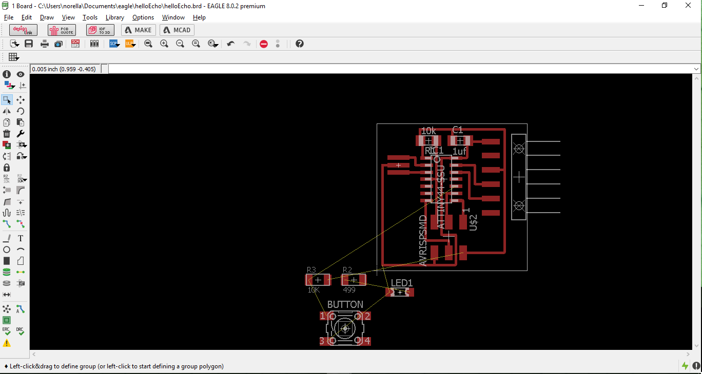
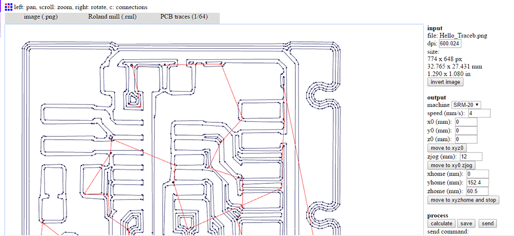
This was my first time designing electronic circuits. I find this experience really amazing. What I learned is not only “How to design electronic circuits” because designing something demands you to know enough about what are you doing, in this case a hello-world board. (image at the left) Following the Fab Academy tutorial I found an opportunity to experiment with some software to process images in order to prepare the file to generate Gcode with Fab Modules. After inserted the components and connected them I continued with the board. (image at the right)

In the images above you can see the process of:
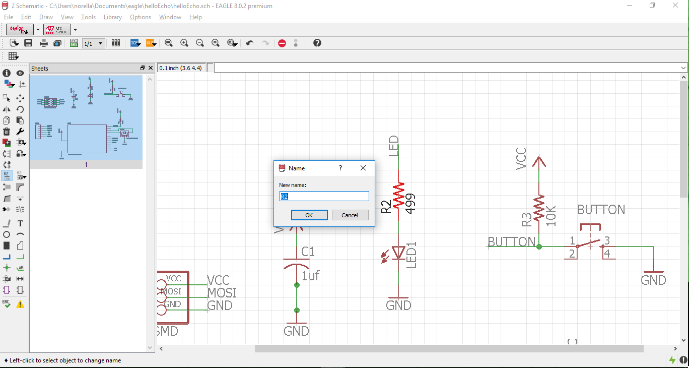
- Inserting Components
- Naming your components
- Building state of Electronic Design
- Building up sequences in electronic design
- Identifying components in the design software (in my case I used EAGEL)
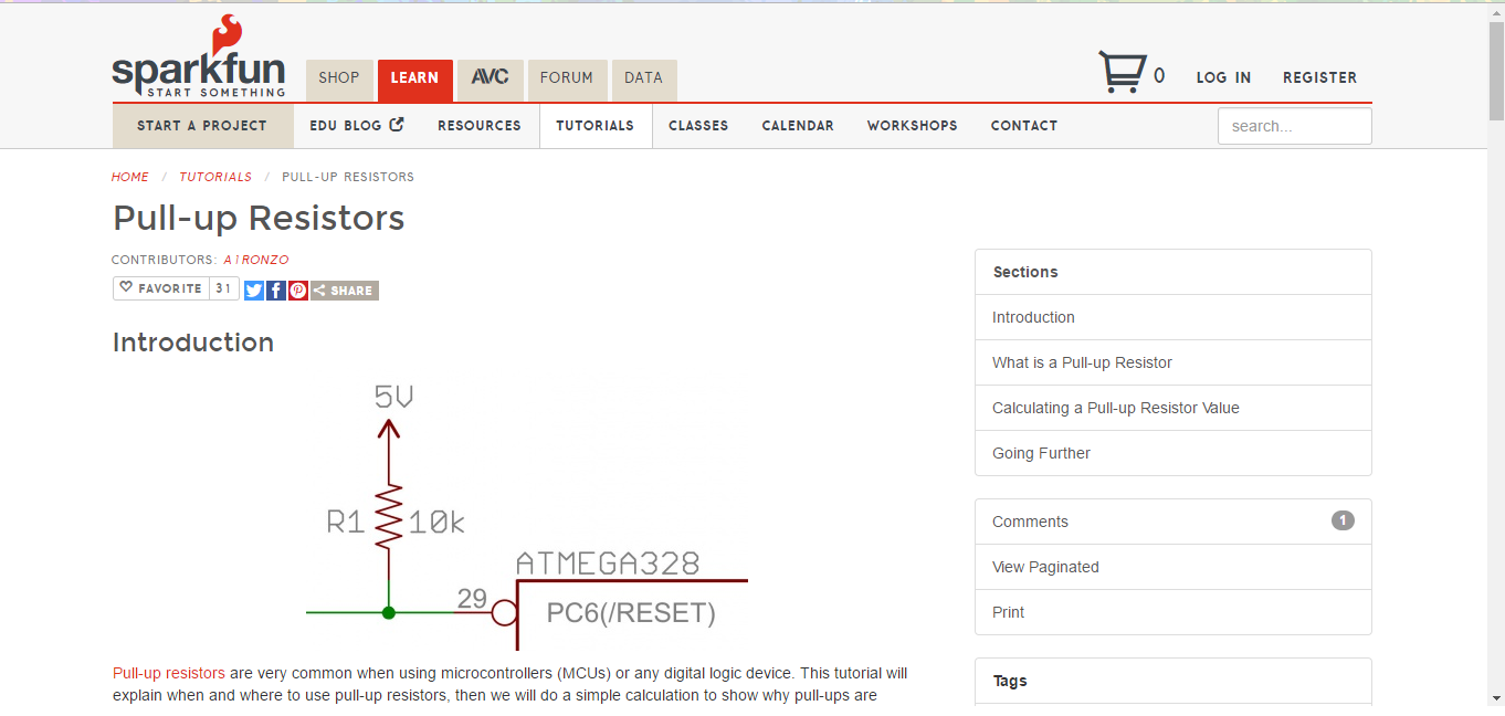
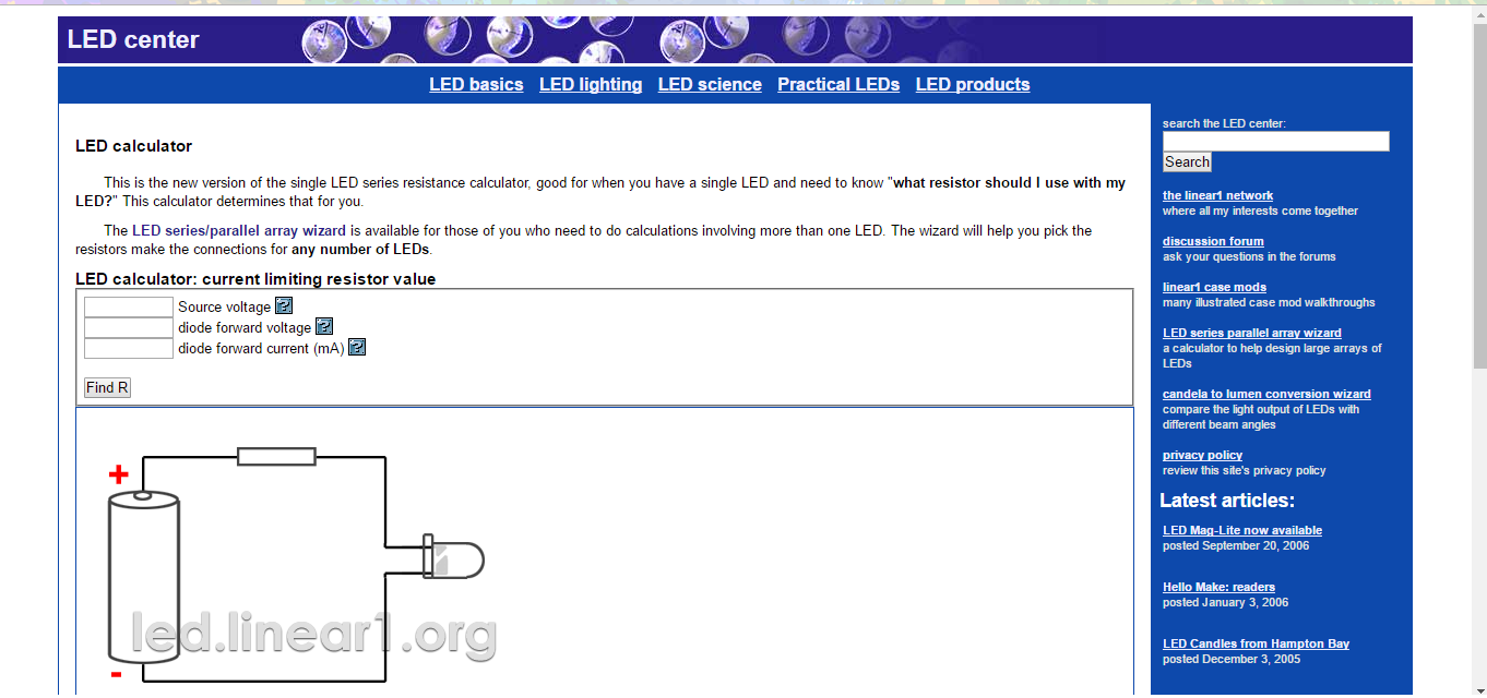
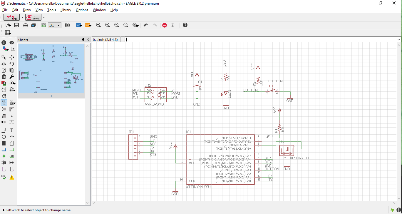
The ATTiny reset pin activates with a low logic level so in the design the RESET pin in the ATtiny has a pull up resistor (image at the left) so the reset pin is at a high logic level and not in a reset state so it can work properly. Understand how to pull resistor. For the LED resistor we need to calculate the value so it limits the amount of current through the LED and thus protecting the micro controller pin. (image at the right) Calculate Resistance.
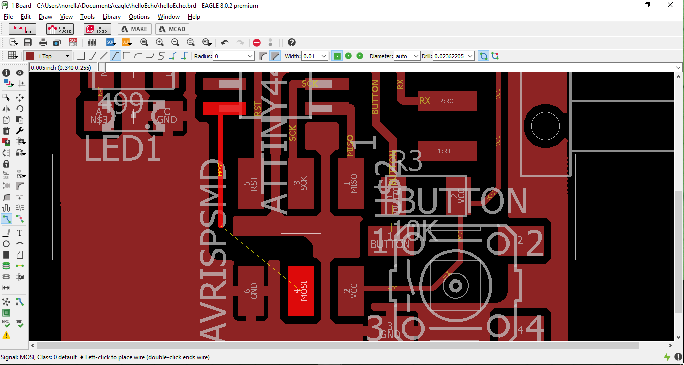
After you finish, you have to change to the Schematic state of Electronic Design, in other words actually design in a physical space to it can be prototype.(image at the left). In the images above you see the process of:
- Schematic state of Electronic Design
- Creating the correct paths
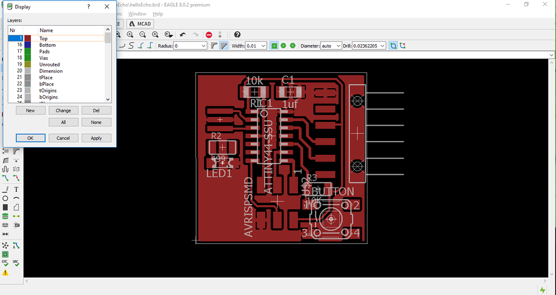
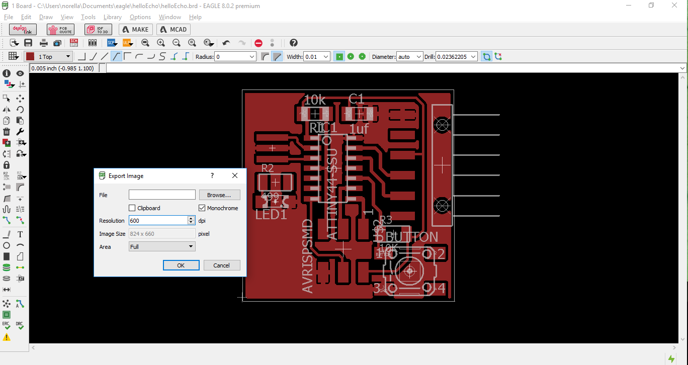
Eagle Software lets you identify which layers you what to save to make your .png file (image at the left) they you finally proceed to import your file (image at the right).
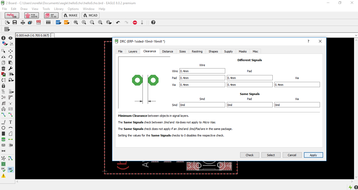
STEPS:(images above):
- Be sure to have a final version of your design
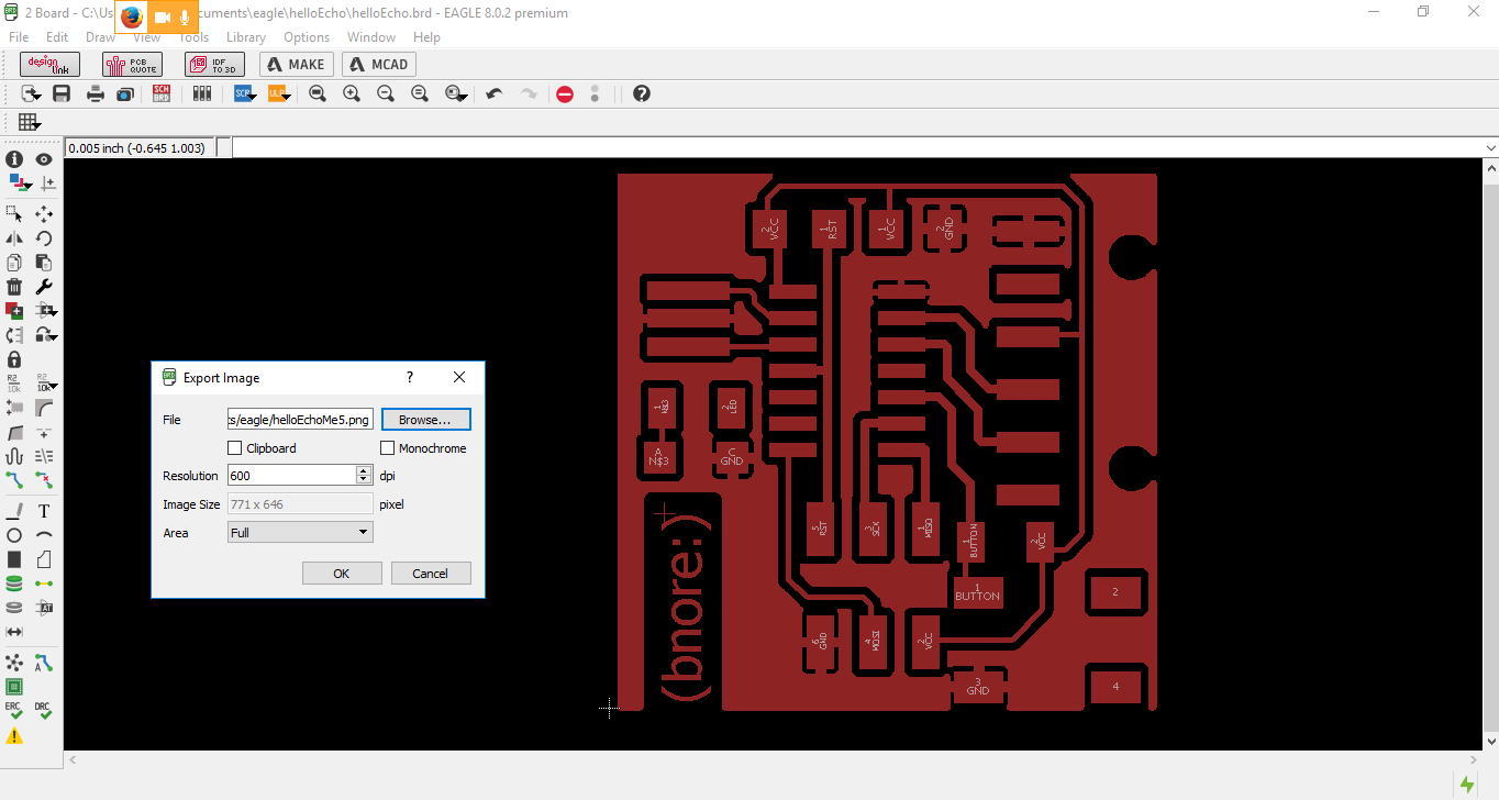
- Export it as .png with a resolution above 500
- Clearances is important based on the thickness of your tool (image at the right)
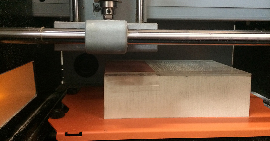
We did settings as before, but not always things end up the right way at the first time. This can be caused by different issues:
- The trace for cut was not done correctly
- When changing the tool accidentally you change the coordinates from the original settings (X, Y AND Z are not in the same positions)
- or as happened to me, both of the above
So i had to re-do my files all over again
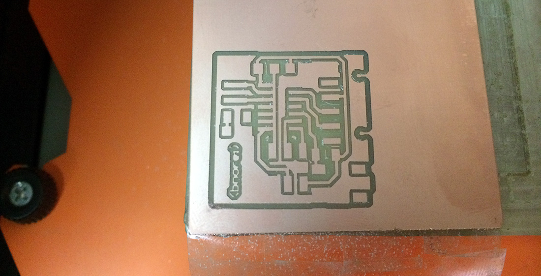
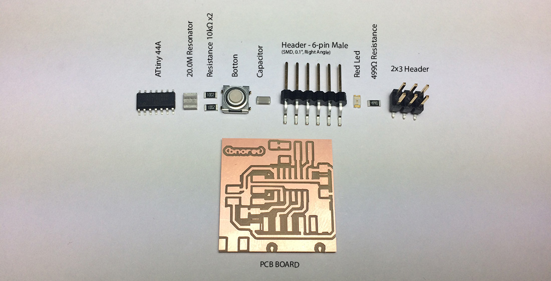
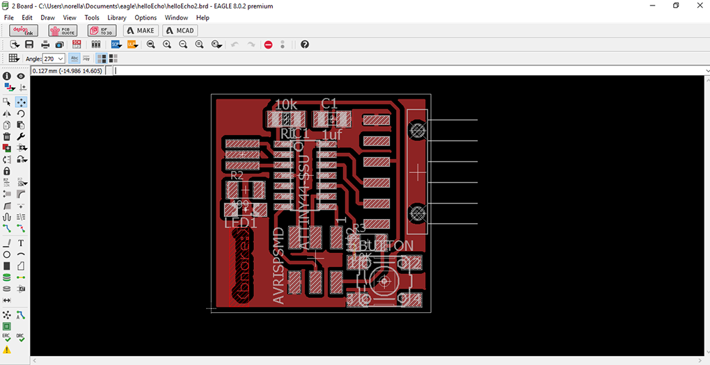
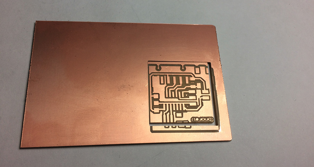
At my second try, thing came out better (image at the left) and then we proceed with the soldering of the components:
- 1 ATtiny44A
- 1 20.0M Resonator
- 2 10Ω Resistance
- 1 Bottom
- 1 6 pin-Header-Male
- 1 red LED
- 1 499Ω Resistance
- 1 2x3 pin-Header
See them above(images at the right)
Electronic Design from Norella Coronell on Vimeo.

Final Result
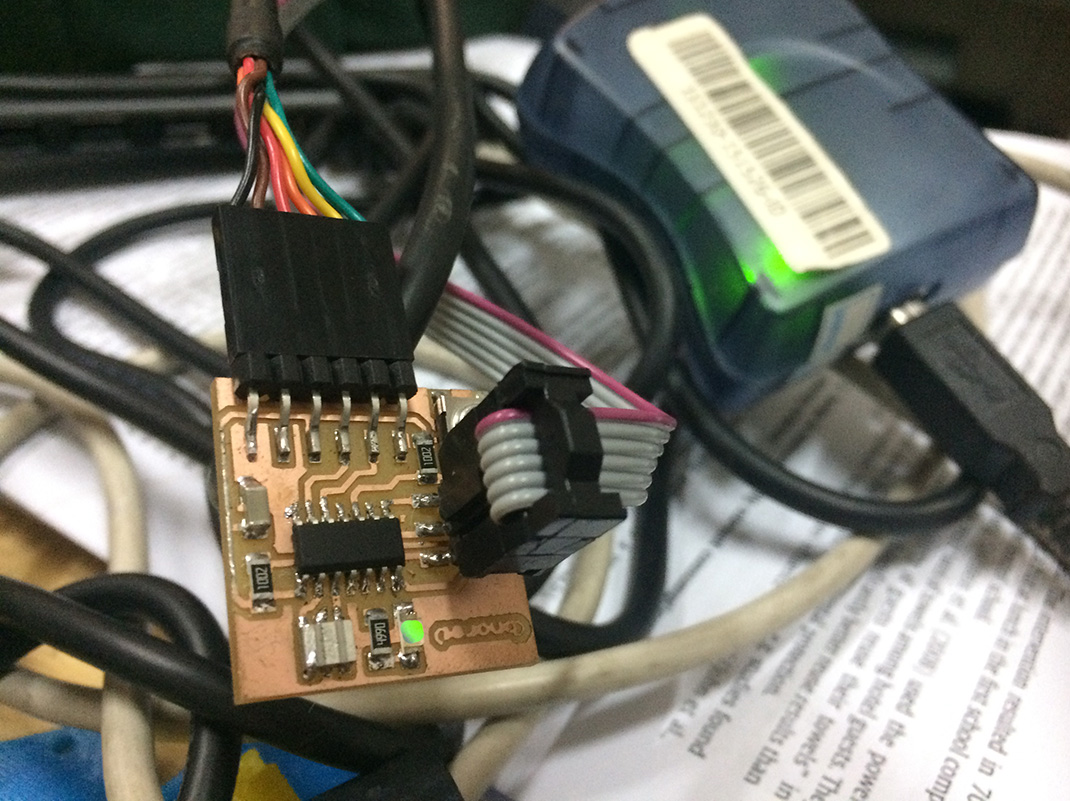
And Finally we make the GREEN LED Blink!
Download Files here:
Bnore Board