Electronics Design
1.3.17Task 1 : Select and use software for circuit board design
Note : For this I selected two Softwares to check which is the easier way to design the circuit board.1. Autodesk Eagle
Autodesk Eagle is the first software I selected for the circuit board design. As it is free and available for MAC OS. and it is one of the most popular tools for the circuit designing. I searched on the Google about "top 10 software for circuit design for mac" and Eagle was 2nd on the list and available for MAC.
Downloaded form the Autodesk Eagle website: http://www.autodesk.com/products/eagle/free-download and did the installation on my Mac.

Step 1 : After installing the Eagle. The first step was to Create a New project and named it to "Raj's Board". Then under that I selected new Schematic.
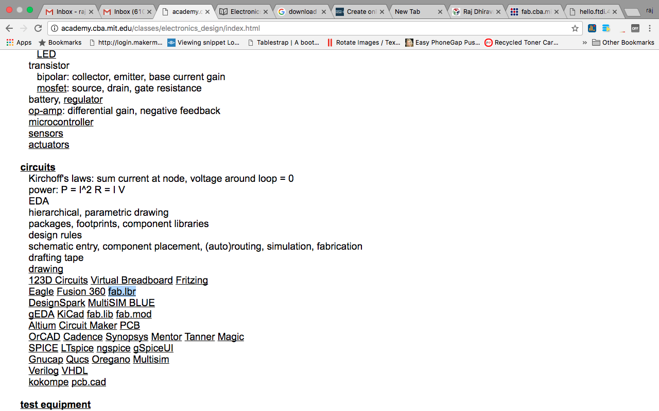
Step 2 : Now for this assignment we require some components which are not predefined in Eagle. So to add all those components there is a library which was given in the fab session that you can download from this link : http://archive.fabacademy.org/archives/2017/doc/electronics/fab.lbr
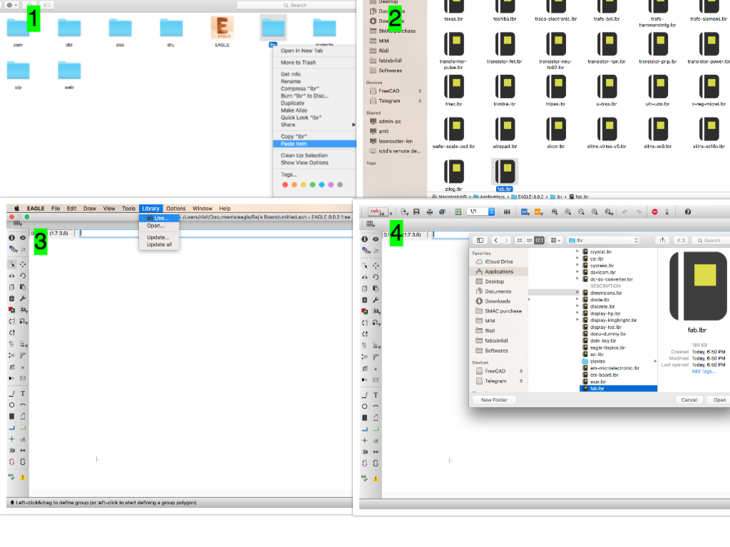
Step 3 : Install and use the library.
1. Copy the downloaded library file "fab.lbr"
2. Paste the file in the installed folder for Eagle under the directory "lbr".
3. Go to Eagle IDE and From Library menu select "Use"
4. Select the fab.lbr.
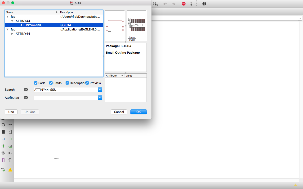
Step 4 : Add components to the schematic by typing "add" in the text field visible in the header and hit Enter.
Browse to the "fab" package and select the required components. You can also use the search. but it is painfull and unless u dont know the full name of the component it does not show the required result.
Step 5 : For creating the design I searched on google about "echo hello world", and this is the first link that opened up :
http://fab.cba.mit.edu/classes/863.14/people/sean_ricks/electronicsdesign.html
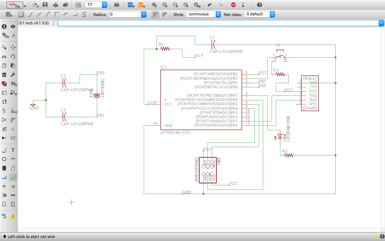
After adding all the components and connecting them via wires. Here is how my schematic looks like :
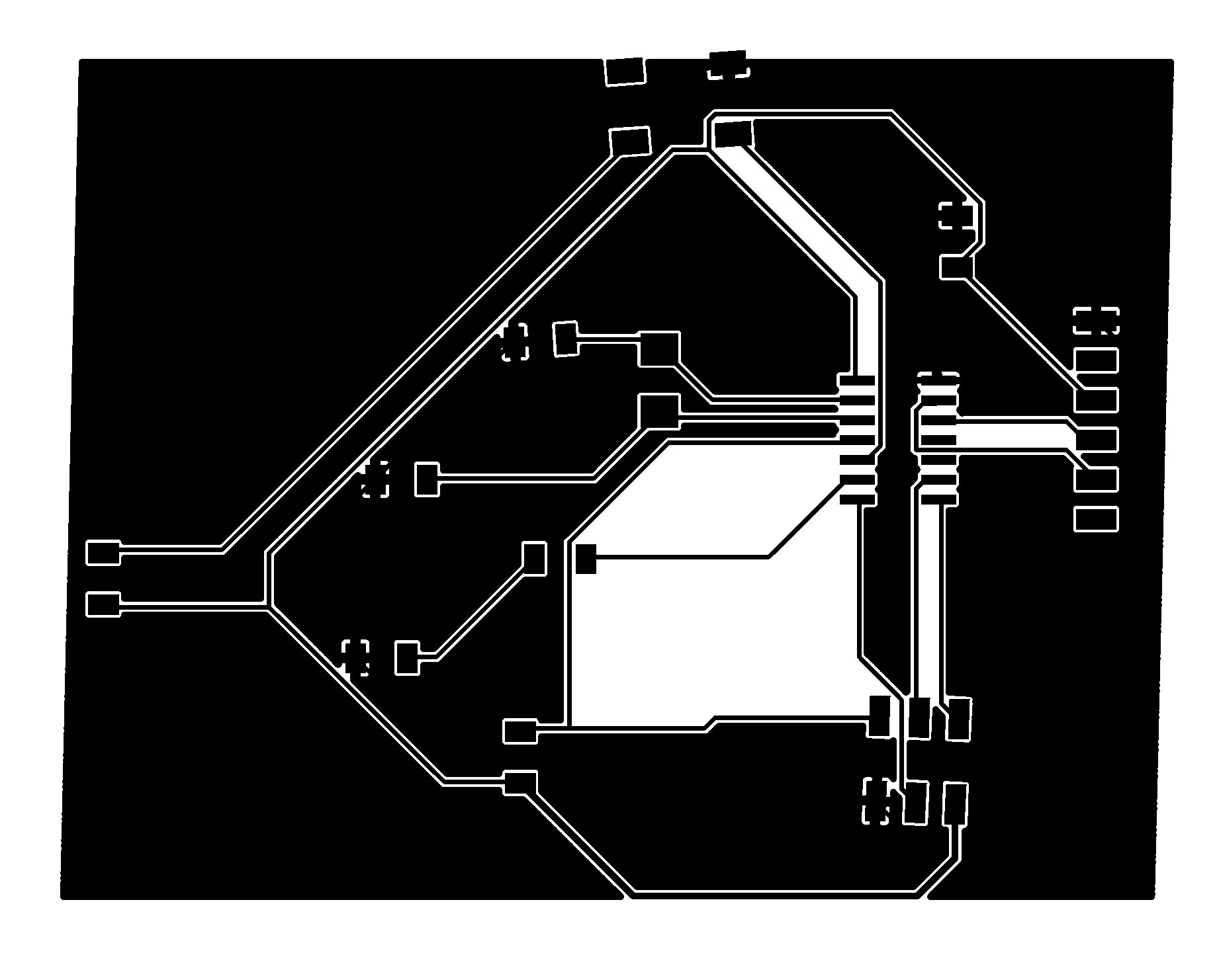
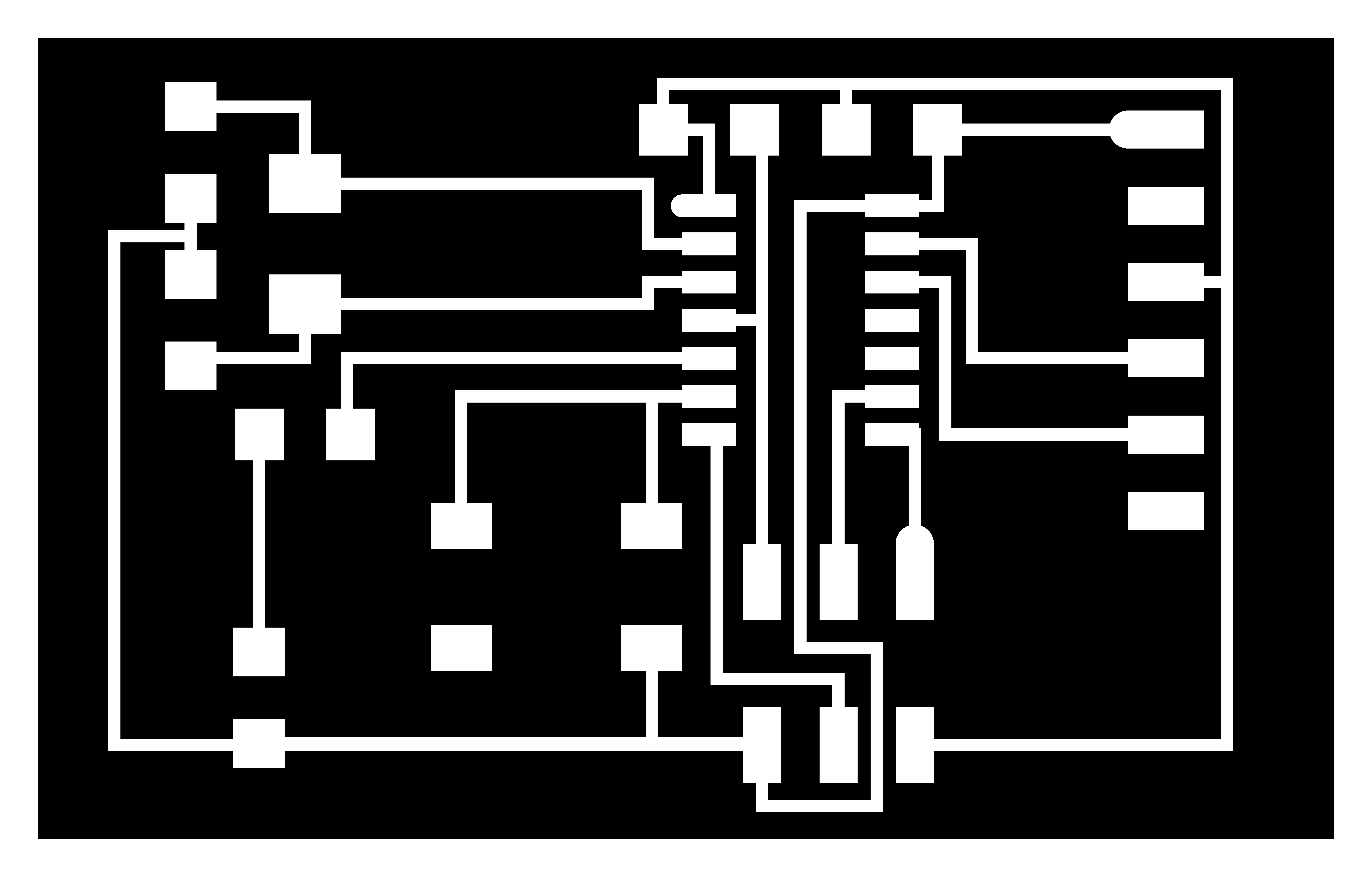
After exporting it to the .PNG format for milling these are the traces :
2. Kokopeli
1. To use this tool I had to switch from my Mac to Ubuntu machine. Thank god I have one old machine at home : Intel(R) Pentium(R) Dual CPU E2220 @ 2.40GHz and 1 GB RAM! yeah thats more than enough to run this software.
How to install Kokopeli ?
Here is the perfect guide for the installation :
http://diyhacking.github.io/Week4/Day1/index.html
Note: At first the installation was not done properly. Then I used update command and followed the installation steps given in the link above.
$ sudo apt-get update
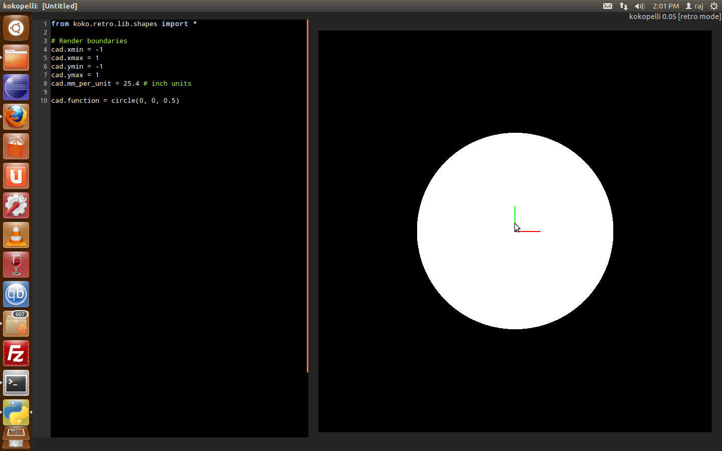
After doing the installation here is the first screen that comes up if you have done the proper installation.
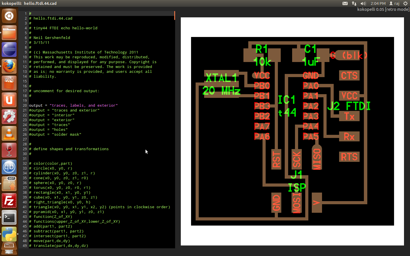
Now after that to get familier with the board. I downloaded the hello.ftdi.44.cad file.
And opened it in the Kokopeli. This is how it looks :
So How it works :
- The file describes about the rules of designing and defines the equipments
- Define board. Go to line number 3595.
a. the first section describes the Output
b. the second section defines the shapes and transformation parameters.
c. text classes and definition
d. pcb classes and definition
e. pcb library
f. connectors
g. switches
h. crystals and resonators
i. diodes, transistors and regulators
j. ICs
Here all the dimension related to board are given
1. You can create pcb with the following function :
2. create ICs and add them to PCB
4. connect two components via Wire function
My task :
1. Replace Resonator with crystal oscillator.
2. Add LED and Resistor
3. Add Button
#
# Changes in the file done by Raj Dhiravani
#
XTAL1 = XTAL_NX5032GA('20\nMHz')
pcb = XTAL1.add(pcb,IC1.x-0.65,IC1.pad[2].y,z,90)
pcb = wire(pcb,w,
XTAL1.pad[2],
point(IC1.pad[2].x-0.08,IC1.pad[2].y,z),
IC1.pad[2])
pcb = wire(pcb,w,
XTAL1.pad[1],
point(IC1.pad[3].x-0.08,IC1.pad[3].y,z),
IC1.pad[3])
C2 = C_1206('C2\n10pF')
pcb = C2.add(pcb,XTAL1.x-.15,XTAL1.y+.12,z,90)
pcb = wire(pcb,w,
C2.pad[2],
XTAL1.pad[2])
C3 = C_1206('C3\n10pF')
pcb = C3.add(pcb,C2.x,XTAL1.y-.1,z,90)
pcb = wire(pcb,w,C2.pad[1],C3.pad[2])
pcb = wire(pcb,w,
XTAL1.pad[1],
point(XTAL1.pad[1].x,IC1.pad[5].y,z),
C3.pad[1])
pcb = wire(pcb,w,
C3.pad[2],
point(C3.pad[2].x,C3.pad[2].y+.05,z),
point(C3.x-.1,J1.pad[6].y,z),
J1.pad[6])
led1 = LED_1206('led1');
pcb = led1.add(pcb,XTAL1.pad[1].x,IC1.pad[7].y,z,180);
R2 = R_1206('R2\n100R');
pcb = R2.add(pcb,XTAL1.pad[1].x-0.06,J1.y-.045,z,270);
pcb = wire(pcb,w,
led1.pad[1],
point(led1.pad[1].x,IC1.pad[5].y,z),
IC1.pad[5])
pcb = wire(pcb,w,led1.pad[2],R2.pad[1]);
pcb = wire(pcb,w,R2.pad[2],J1.pad[6]);
btn1 = button_6mm("BTN1");
pcb = btn1.add(pcb, IC1.pad[6].x-0.2,J1.y+0.1,z);
pcb = wire(pcb,w,IC1.pad[6],btn1.pad[1]);
pcb = wire(pcb,w,IC1.pad[6],btn1.pad[4]);
pcb = wire(pcb,w,btn1.pad[3],point(btn1.pad[3].x,J1.pad[6].y),J1.pad[6]);
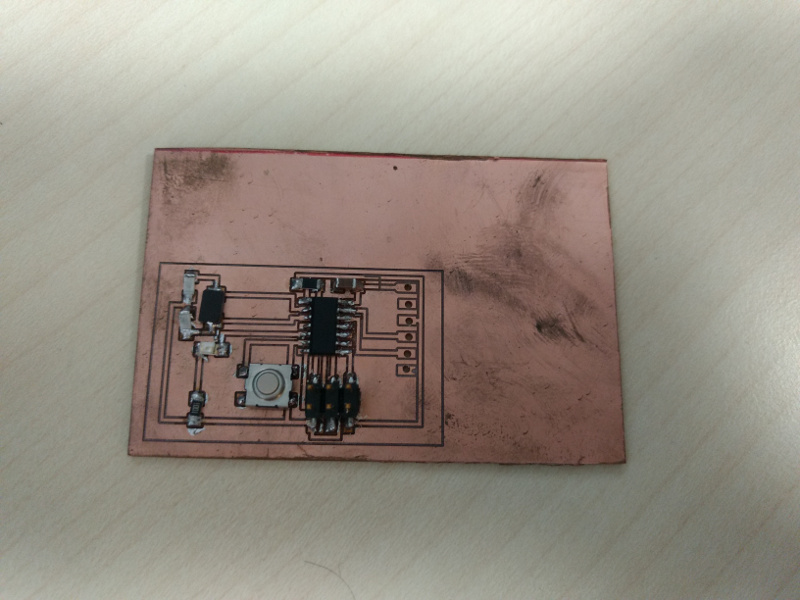
My Board after milling and soldering the components. I have not added some components due to unavailability hence the testing remains.