Electronics Production
15.2.17Task 1 : Make an in-circuit programmer by milling the PCB
Started with downloading the png file http://academy.cba.mit.edu/classes/embedded_programming/hello.ISP.44.interior.png
About Fab ISP : The FabISP is an in-system programmer for AVR microcontrollers, designed for production within a FabLab. That is, it allows you to program the microcontrollers on other boards you make, using nothing but a USB cable and 6-pin IDC to 6-pin IDC cable. It's based on the USBtiny and V-USB firmwares, which allow the ATtiny44 to perform USB communication in software. Programming can be done through avrdude. The schematic (PDF) is super simple: USB connector, ATtiny44, and 6-pin ISP header, with assorted passive components. I started with the Eagle files for the USBtinyISP, although there's almost nothing left of it. Most of the parts for the FabISP are in the FabLab inventory. Exceptions include the Mini-B USB connector (SparkFun, Digi-Key), 12 MHz crystal (Digi-Key), and 18 pF capacitors for the crystal (Digi-Key).
Website url : http://fab.cba.mit.edu/content/projects/fabisp/
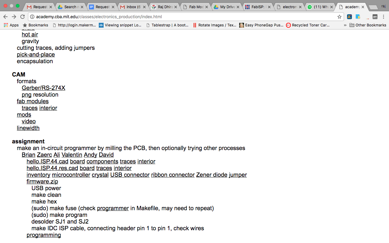
Scrolling down to the download section. Where I downloaded two files traces and interior.
After downloading the files. Its time to do the configurations according to the Milling machine. For that I have used Fab modules.
The Fab module is the interface between the input design image and the machine. It converts the input file into selected output file on the Node JS server and passes on to the machine u select. The interface is via USB cable.
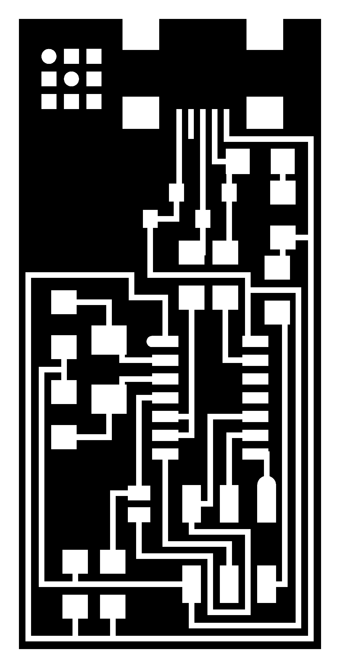
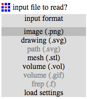
Upload the file (hello.ISP.44.traces.png) on "Input section" select .PNG
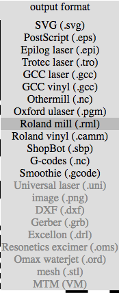
Now select the Output format according to the need. In my case it is .rml Because we are doing milling and the machine used for that is Roland Modela MDX20. It uses the file format of .rml to read.
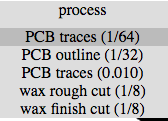
After selecting the output format select Process. Since we are doing traces on the PCB. Select PCB traces (1/64). To do the outline select PCB Outline (1/32). Also according to that the end mill will change.
Connect the machine via USB Port. The machine which I was using had a Serial port so had to use USB to Serial converter.
Machine used : Roland Modela MDX 20
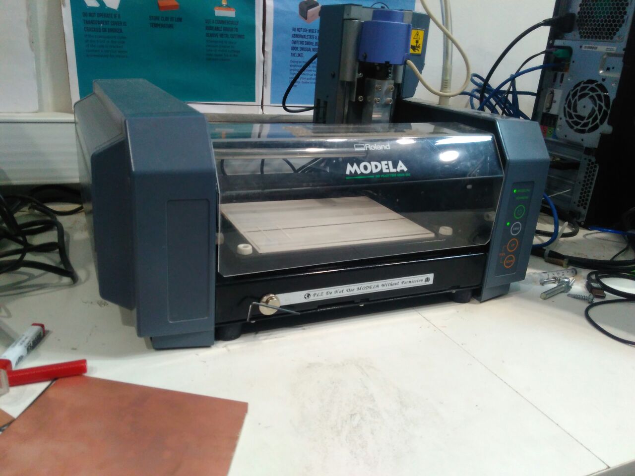
Select the machine from the output options. In my case it MDX-20. Set the X-Y positions accordingly and place the PCB.
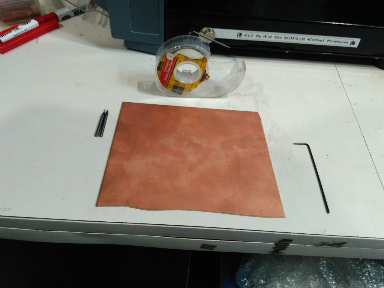
We used double sided tape before starting the milling process. Because end mill is sensitive.
There are various PCBs available in the market. But as it was recommended in Fab Academy lecture I used FR-1.
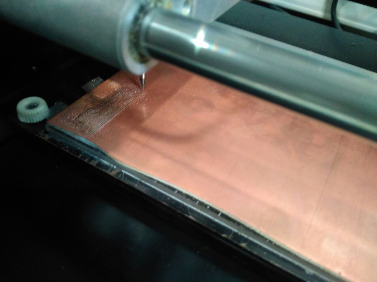
Setting the XY Position was easy. But to set the Z position it is not recommended by setting it via the Software interface. So had to do it manually using up down buttons and then after placing it correctly on the XY I loosen up the end mill to slightly touch the PCB. So when it was touching the PCB I made the end mill tight.
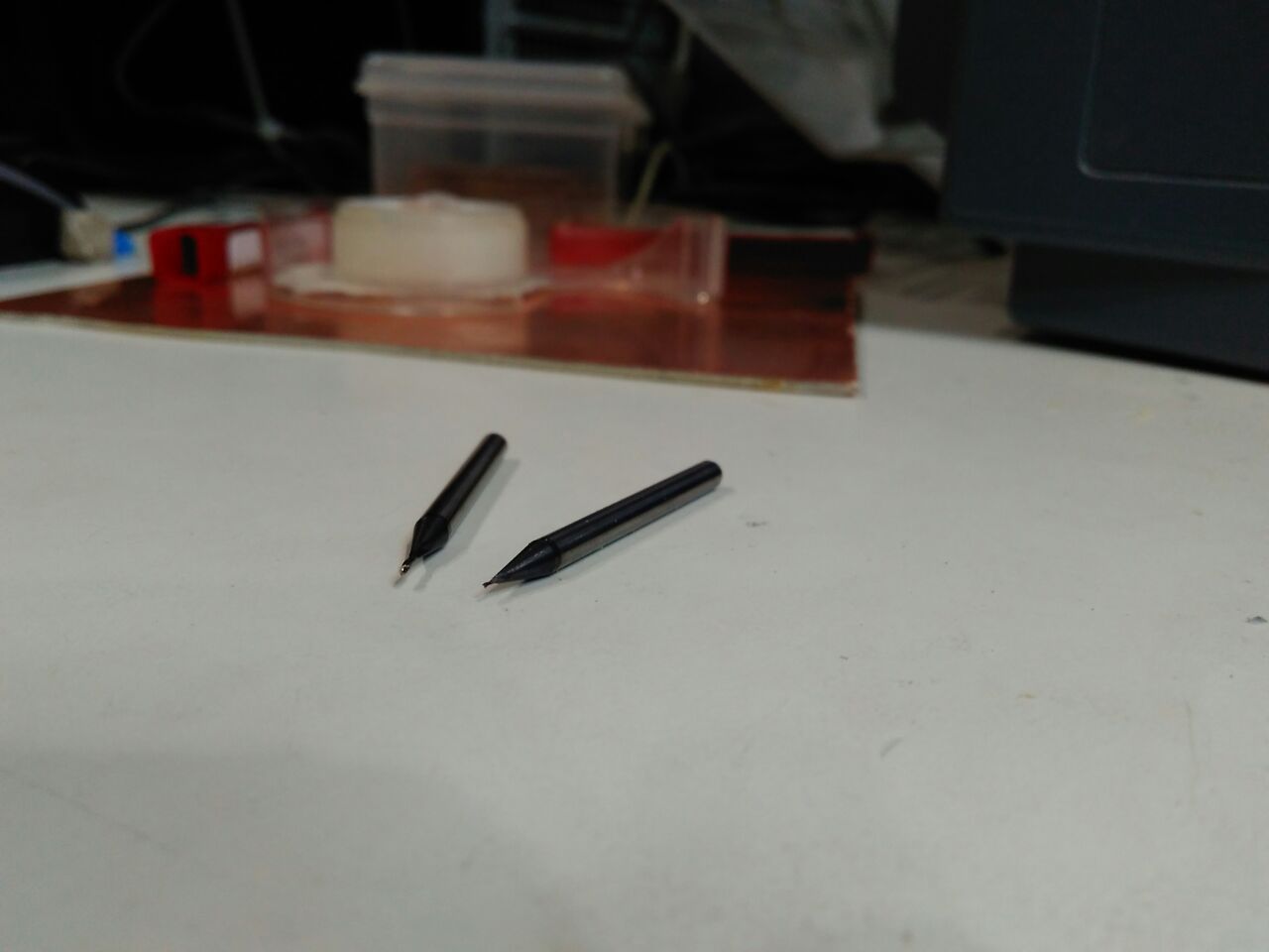
There are 2 end mills available 1/64 is used to do the traces and 1/32 is used to cut the board. Here I started with 1/64.
After doing all the proper setting. Click on the Start button to start the milling !
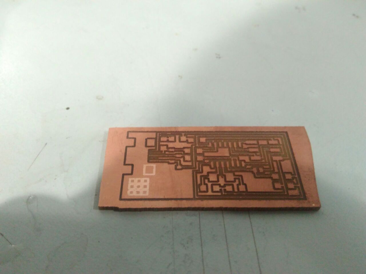
Now after tracing following the same set of steps for cutting the PCB. For that use hello.ISP.44.interior.png and change the end mill to 1/32.
The Final output after tracing and cutting is :
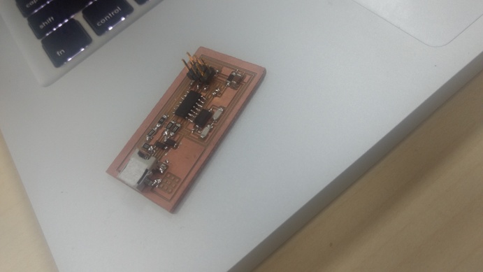
After attaching/soldering components it looks like :
Next task is to Program the pcb. To do that I started with searching about fabisp programming. Found the link on google : http://fab.cba.mit.edu/classes/MAS.863/doc/tutorials/fabisp_programming/#program
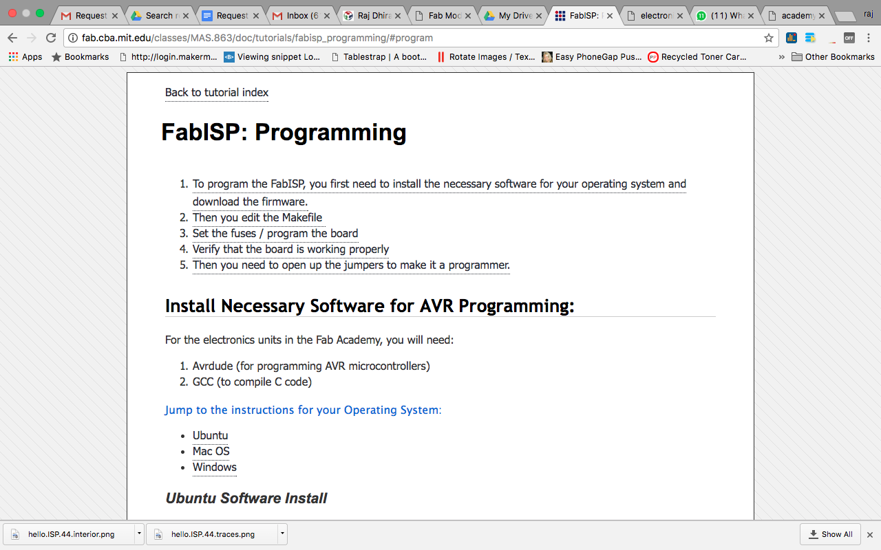
1. To program the FabISP, you first need to install the necessary software for your operating system and download the firmware.
Mac OS Software Install :
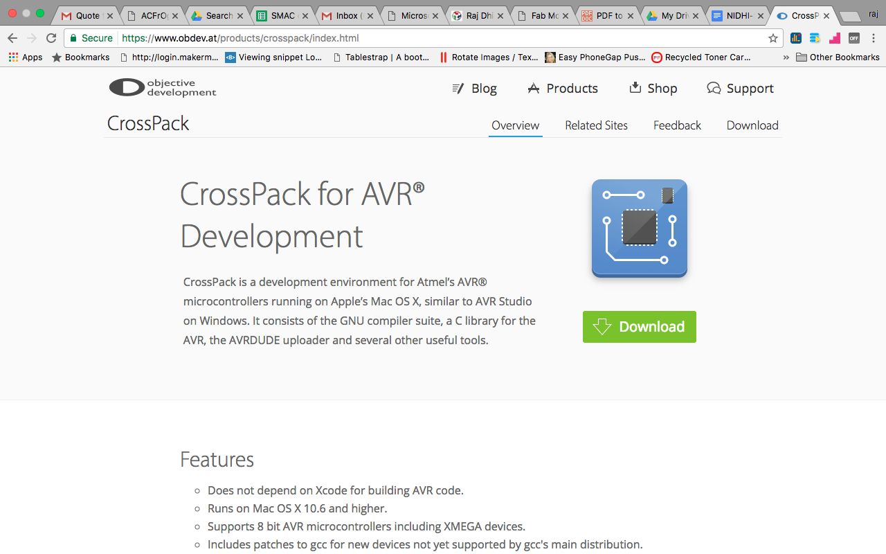
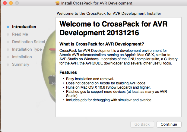
a. Download and Install Crosspack AVR - Has an installer. Url : http://www.obdev.at/products/crosspack/index.html
Installing is very easy. Just double click on .dmg file.
b. Get Make (via XCode). As Xcode was already installed on my Mac had nothing to do to install "Make".
Then I downloaded FABISP Firmware.
Open terminal navigate to the desktop:
cd desktop
Unzip the fabISP_0.8.2_firmware.zip directory:
unzip fabISP_0.8.2_firmware.zip
Move into the newly created firmware directory on your desktop
cd /Desktop/firmware
2. Then you edit the Makefile
Now open and edit the Makefile. For my macos I simply opened it in the Textedit.
Copied form the fabisp website :
A window will open containing the Makefile. Go to the line that says:
#AVRDUDE = avrdude -c usbtiny -p $(DEVICE) # edit this line for your programmer
AVRDUDE = avrdude -c avrisp2 -P usb -p $(DEVICE) # edit this line for your programmer
- If using the USBtiny programmer or another FabISP
- Remove the "#" in front of the line with "usbtiny" in it
- Add a "#" to beginning the line with the "avrisp2" in it to comment it out.
- save the Makefile
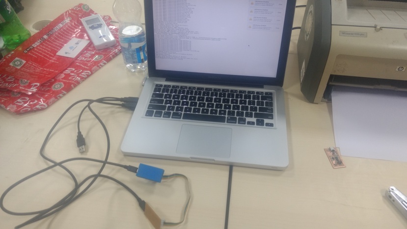
3. Program the FabISP : Connected FABISP made by my lab instructor to program my PCB. Connection : Connect both the devices using USB connection. And use FRC cable to connect my device to FABISP (already programmed device).
Used series of commands to do the execution.
cd Desktop/fabISP_mac.0.8.2_firmware
make clean
make hex
make fuse
make program
Due to some issues on MAC maybe because of USB 3.0. I could not program it using MAC OS. So to complete the assignment I used Windows laptop and performed the same steps. And it was done successfully.