Computer-Controlled Cutting
8.2.17Task 1 : Demonstrate and describe parametric modelling processes
Software used
- Autodesk Fusion 360
I will be using Autodesk Fusion 360 for parametric modeling process and laser cutting. I previously had no experience with it. It was really difficult to understand the crux of Autodesk Fusion 360 as it is very detailed and comes with lots of options to manipulate the object.
When I was searching about parametric design tool there were lots of other options like Antimony, Freecad etc. Choosing Autodesk Fusion 360 above the other tools was I found it very user friendly as I had a little tricks on Freecad and was little difficult to understand, Antimony on the other hand was quite complex as it was following a unique flowchart process flow. Turend out Autodesk Fusion 360 was available for MAC, so I selected to explore more on it.
Soon I experienced there were lot of features. Creating Parametric design for the first time was a whole new journey. Sharing my experience :
Downloading Autodesk Fusion 360 for MAC. Go to http://www.autodesk.com/products/fusion-360/overview
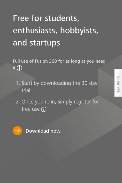
To download the software I had to register with the Autodesk, I previously had no account and after discussing with my colleague I found there is a free trial for students so I used my email ID @somaiya.edu for the registration so I got 3 years of license free. After successful registration I downloaded the .dmg file which was later used to download the entire package of Autodesk Fusion 360. After few minutes download was complete and I could see the first screen to begin with.
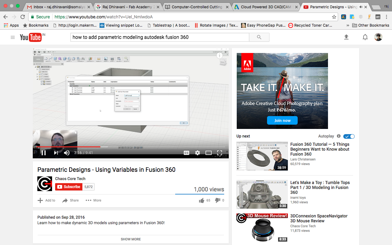
Understanding the Autodesk Fusion 360 was not easy in case of demonstrating the parametric design so I used number of youtube videos to understand it.
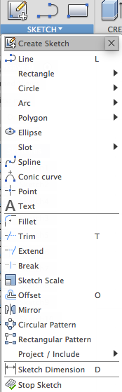
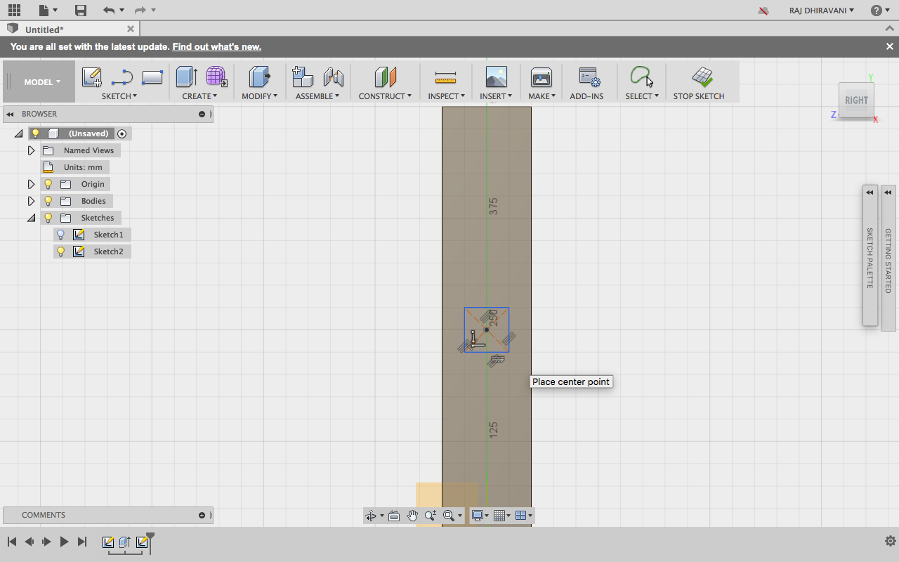
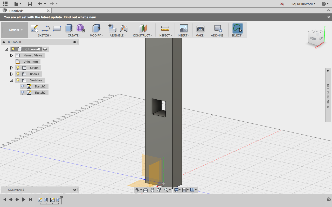
I started with the construction of a rectangle and was trying to adjust the parameters of it.
I created a new sketch to draw the rectangle and for each shape I was gonna use different sketch, the advantage of doing this is you get more power in handling the objects when you sketch them differently. for e.g. show/hide sketch etc.
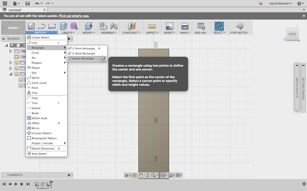
As displayed in the screenshot above it clearly says that one create a rectangle by defining two points. 1. Center and 2. Corner. for the 2nd you can later specify the width and the height of the rectangle.
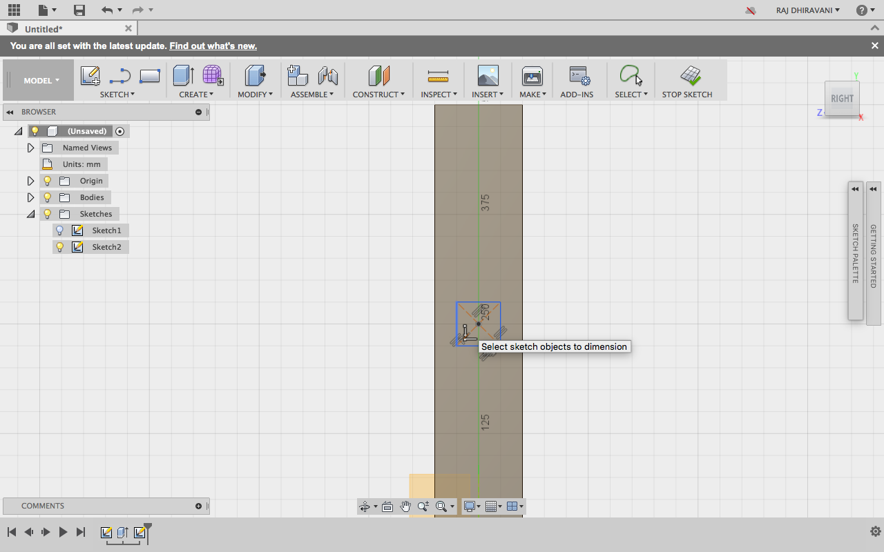
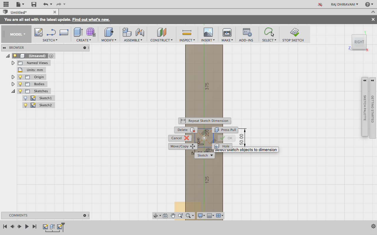
While defining the dimensions one can also convert into a 3D my using presspull function.
1. Just right click on the design you want to give dimension to.
2. Select the presspull feature from the popup.
3. Select the surface.
4. Give dimension.
(1)
(2)
(3)
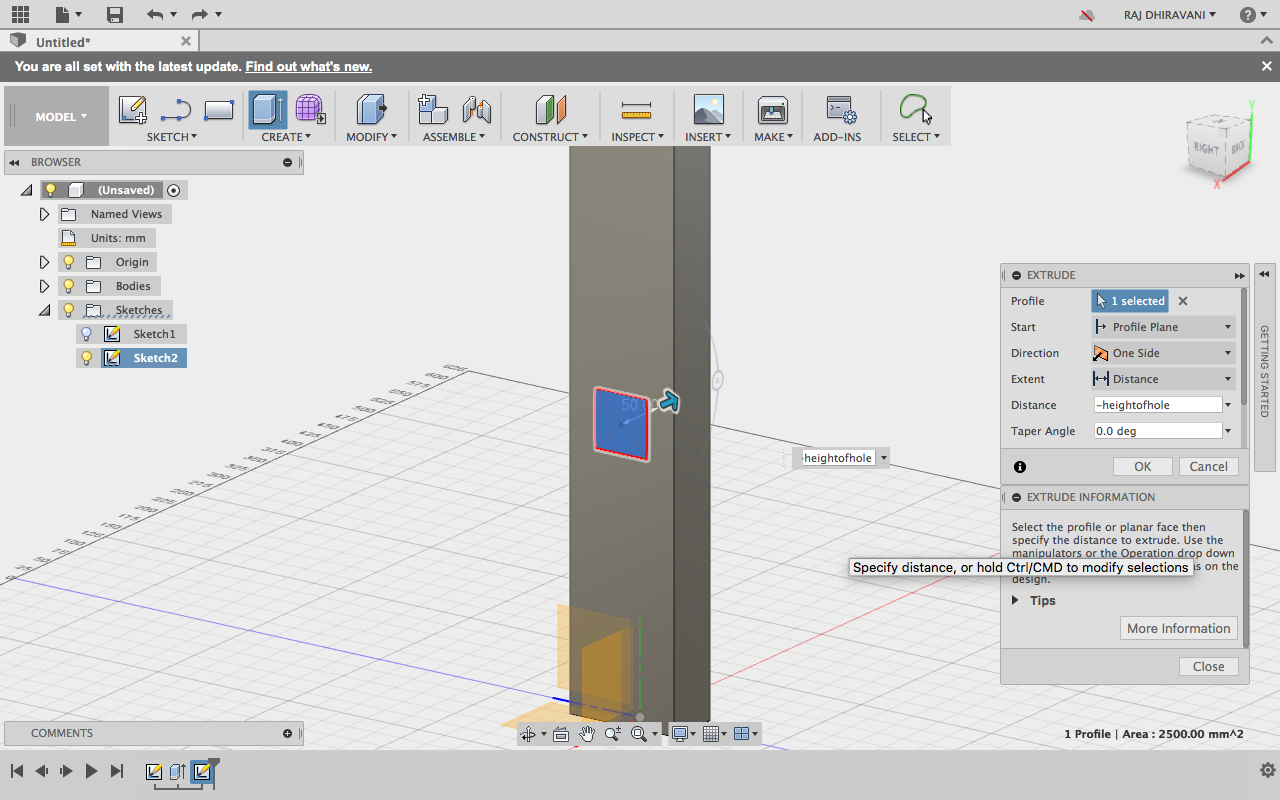
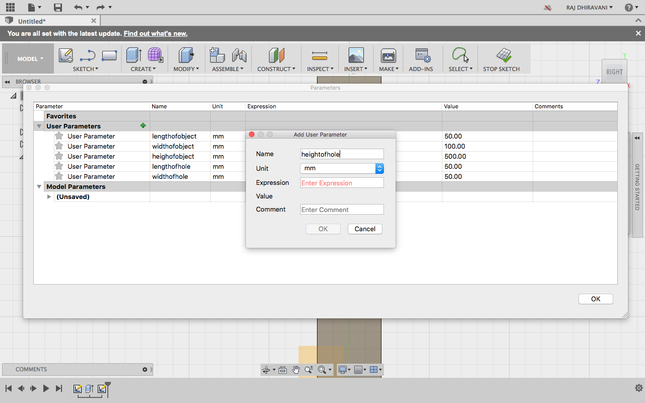
Now its timet to create the parametric expressions. I started with defining the length, width, height of the object :
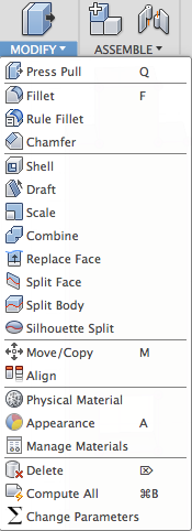
Go to Modify tool and select Change parameters
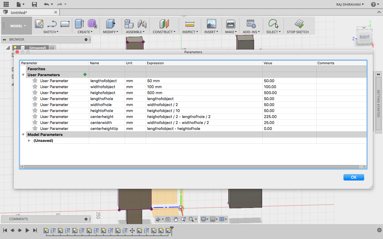
I changed the expressions for the length, width, height of the hole I created and defined it by relating it to rectangle object. So whenever the dimension of the object changes, the dimension of the hole also changes.
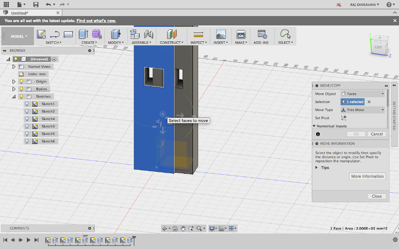
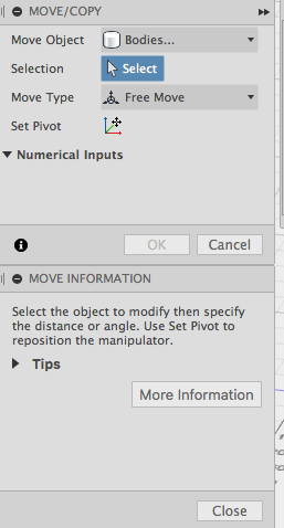
After that I created a second tower, when I increased the size of both towers the tower collided with each other so I had to move one of the towers in order to get the proper result. To do that I selected the the object first and then pressed "KEY M" so a popbox appeared with move related features. Using that I was able to translate/move the object. But I had to select "Bodies" in Move object option.
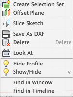
After completing my design I exported the individual design by seleting the design and pressing "KEY P" after this a New sketch was ready. I did right click on the sketch and the menu poped up with options. I selected Save as DXF.
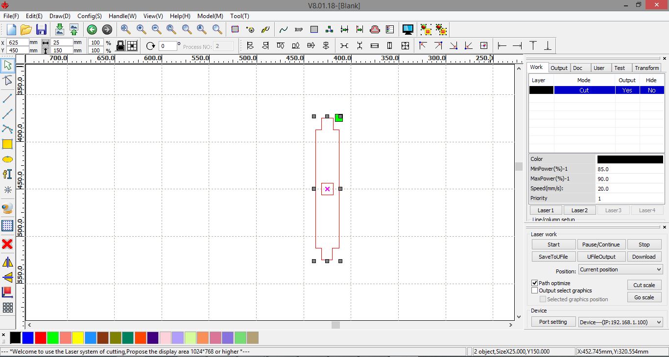
I exported .dxf file for both the towers and then imported those files into RD Works. There I had to adjust various parameters like Power and speed. Also I did some scaling on RD works to make the Towers small. After that I selected Download button and the file was imported to Laser cutter machine which was connected via Lan port.
Configurations :
Min Power : 85
Max Power : 90
Speed : 20
After downloading file to laser cutter machine, there were various options on the machine. First I selected my file using "File" button. After that I placed the material in the machine and selected Origin by moving the laser head via Arrow keys. After setting the origin I selected "Frame" option to check whether the frame is proper or not. Once the Frame was set I selected "Start" button to start the cutting. This is how it looked :
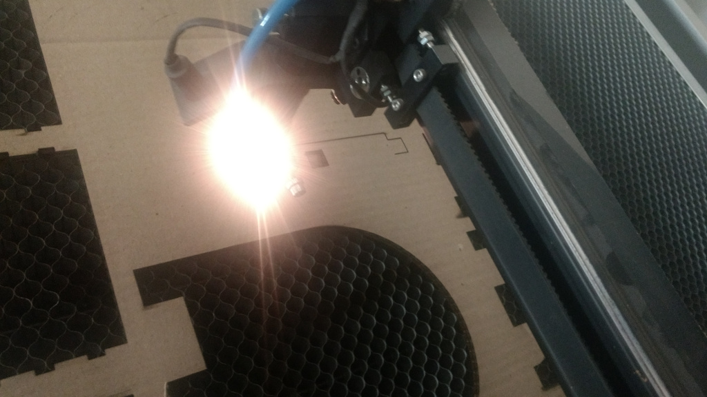
After downloading file to laser cutter machine, there were various options on the machine. First I selected my file using "File" button. After that I placed the material in the machine and selected Origin by moving the laser head via Arrow keys. After setting the origin I selected "Frame" option to check whether the frame is proper or not. Once the Frame was set I selected "Start" button to start the cutting. This is how it looked :
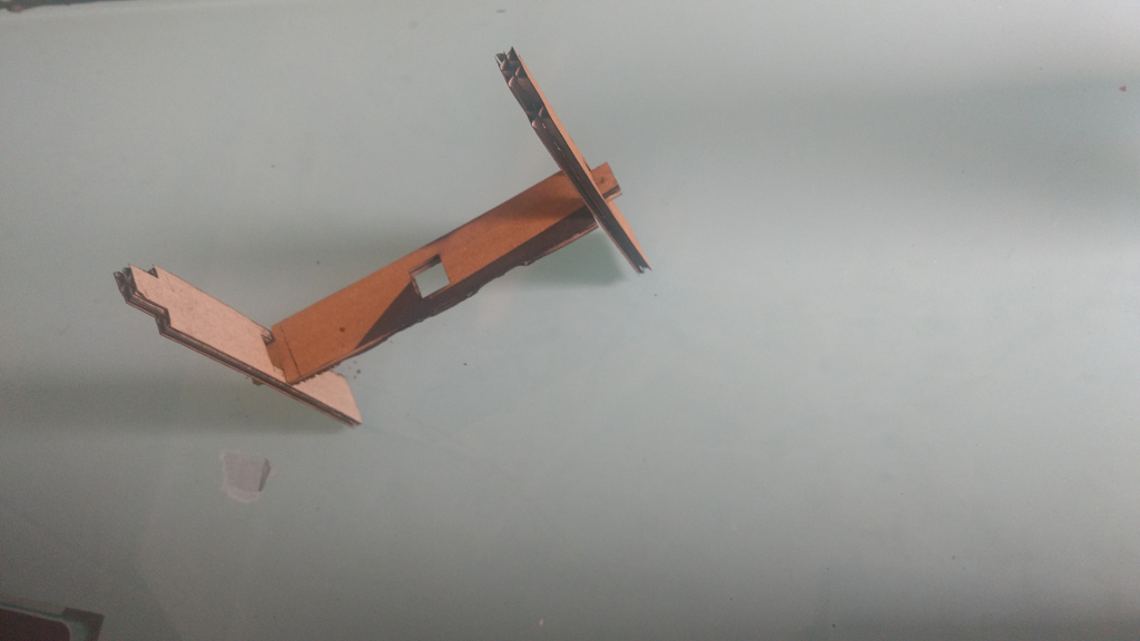
Group Assignment - Idol stand
- We created a design using Autodesk Fusion 360.
- We created a rectangle of size (l = 112mm, b = 70mm) using the sketch tool. Also, we create a circle of radius 56mm
- WE clicked the modify button and then selected the combine tool to combine the two shapes.
- To create a notch in the above plate, we created a notch of length 40mm x height 20mm and the distance between the notch and the edge of the plate is 15mm. Also, the distance between the two notch is 40mm.
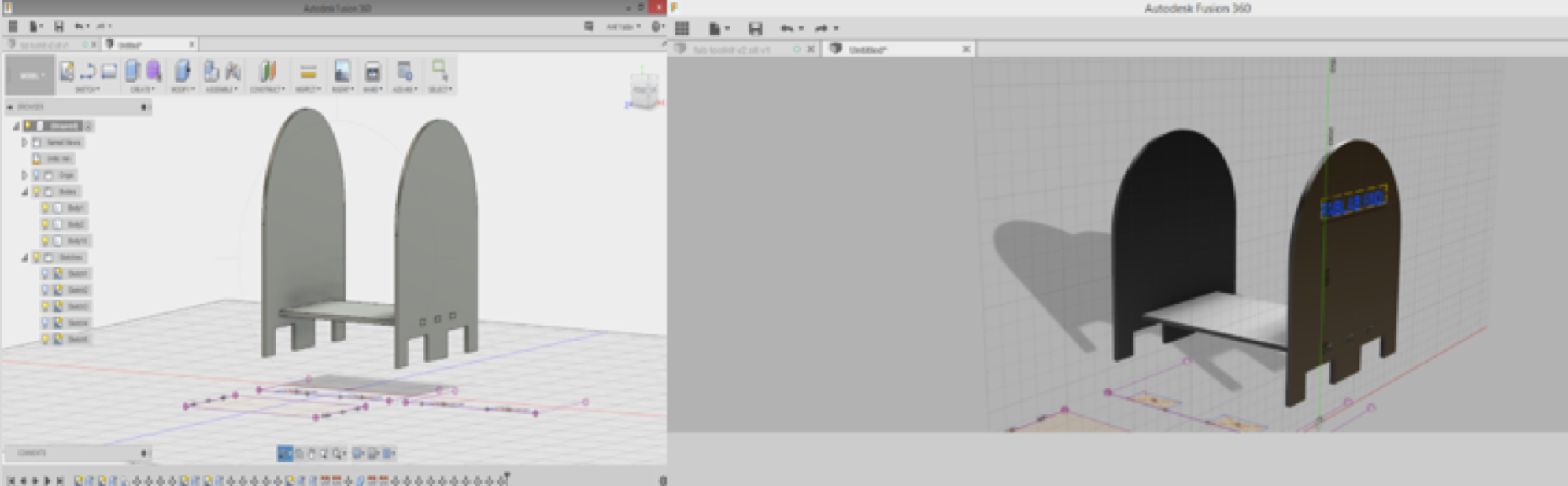
- We create a copy of the same file i.e replicated the same design to create the second plate.
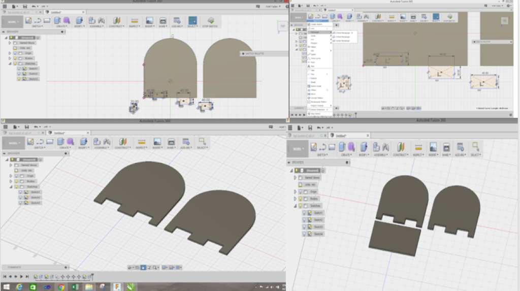
- We create another rectangle of length 112m x breadth 70mm as shown in the figure.
- We create three notches on each side of the rectangle and the created 2D, dxf files from the 3D file we sketched.
Laser Cutter Configuration
Machine type : CO2 Laser
Size : 900mm X 1200mm
Operations : Cutting and Engraving
Laser Tube : 100 Watts
Task 2 : Vinyl Cutting - Stickers
To Start with I created a design of my name in Corel Draw. Then to print with I did some modifications in my design :
Go to Objects -> convert to curves -> Select outline color black -> select fill color white.
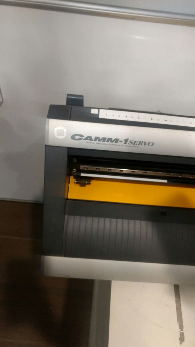
Machine Used : GX-24 - Desktop Vinyl Cutter by Roland
Range : 700mm wide Vinyl cutting
(1) The handle was up while I was loading the vinyl.
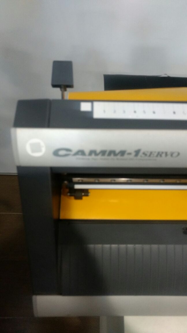
(2) I put the handle down after inserting the sheet of vinyl.
(3) Adjust the cutting force (GF - Gravitational Force) using the panel attached on the machine.
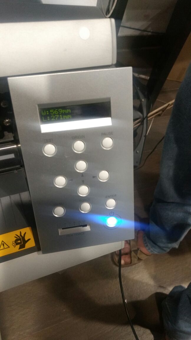
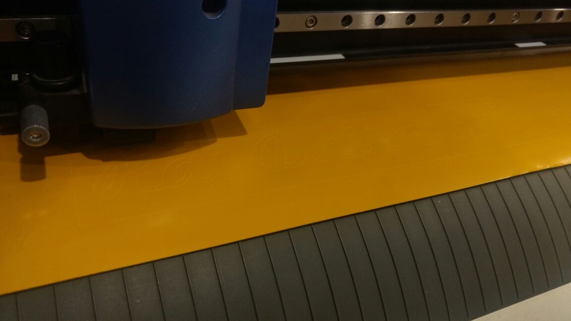
The main important point of starting the whole process is the measuring the size of the material which will be working on. Entering proper size of the Vinyl is necessary to align the designed graphics properly on the available/usable vinyl area to reduce the wastage.
Cutting force : 100
After issuing the print ctrl + p in the dialogue box presented select the vinyl cutter from the list and edit the preferences according to sizing of the vinyl sheet loaded there's one more option to read the size of the vinyl sheet directly from the GX-24 for the same Get from printer.
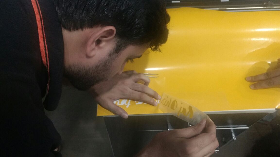
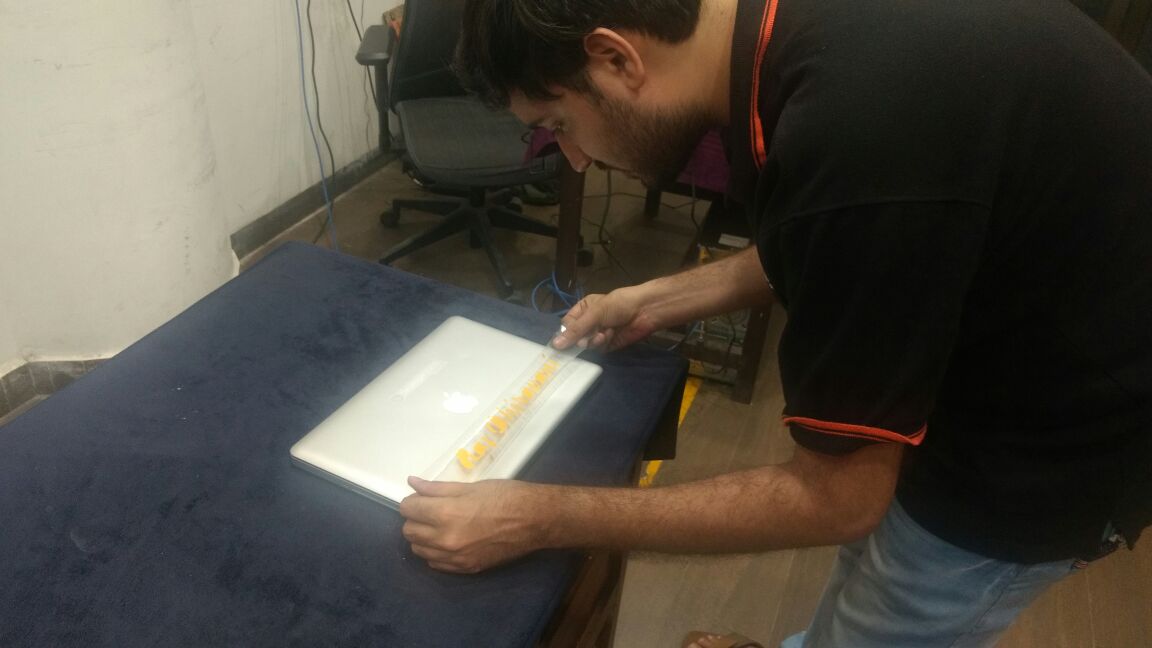
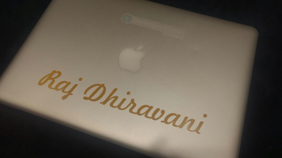
Had to tear off the final output with the cellotape. And Applied that cellotape on my macbook. After that using Tweezer I removed the unwanted parts. Here is the final output :