Final Project
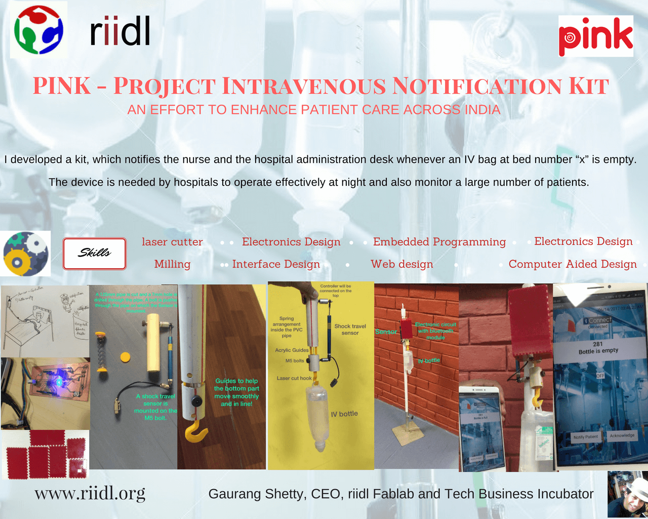
2.5.17Project Intravenous Notification Kit : PINK - An effort to enhance patient care across India and all other developing countries
Problem / Opportunity statement
The IV kits currently present in the market are not smart. They have to be manually controlled and removed by the nurse. Specially at night the situation becomes intense. Saline bottles and other drugs which are usually given through these IV kits needs to be monitored. This is very cumbersome where the density of the patients is high or in case of a natural calamity / war, monitoring the IV kits can be time consuming. With reference to my conversations, with several doctors, this is common problem across India. The patients usually remain unattended unless the family member who sits besides the patient, calls the nurse.
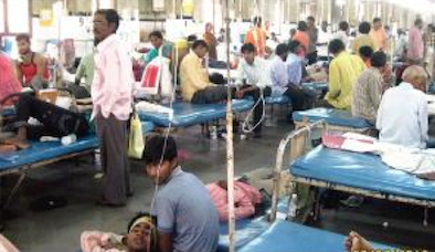
Image of KEM Hospital, source: Mumbai Mirror
The major issue of these bottles are they are not monitored. Once, the fluid in these bottles are over, it tries to pull blood back from the body, which is dangerous. Excess quantity of fluids are dispensed sometimes,which again can be harmful.
Proposed Solution's sketch
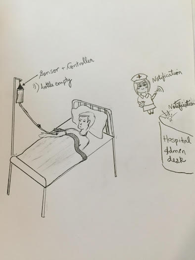
I am trying to develop a sensor & notification device, which will notify the nurse and the hospital administration desk, whenever an IV bag at bed number “x” is empty.
Future development:
I would like to develop addon’s to this kit, where in we can control the micro droplets and stop the fluids whenever the fluid is empty or the necessary concentration of the fluid is dispensed
Project planning Gantt Chart

Logo Design:

Downloadable file of my logo: cdr format
Process
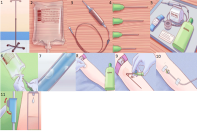
1. Procure the IV Stand
2. Having the right IV bag(s) (Attach the sensor between the IV stand and the IV bag)
3. A Set: A set is the tube and connector that regulate how much fluid the patient will get. A macroset is used when you are supposed to give the patient 20 drops per minute, or about 100 mL per hour. Adults generally receive a macroset. A microset is used when you want to give the patient 60 drops of IV fluid per minute. Infants, toddlers, and younger children generally need a microset (This is manually done now. Future automation of drops from the bag will be done post fab academy program)
4. Get the right size of needle
5. Gathering supplies
6. Prepare the IV Bag: Pipe or insert the macroset or microset through the IV bag then hang it on the IV stand.
7. Get rid of the bubbles
8. Clean the spot where you will insert the cannula.
9. Inserting the Cannula (Dummy model)
10. Giving the patient (Dummy model) an IV
11. Regulate drops per minute ( A notification will be sent to the nurse and the Admin desk, if the IV Bag is empty.)
12. Making the Android app on App inventor.
13. Testing the App with the kit, using a bluetooth SPP (Serial Port Protocol) module HC-05
Steps to do the assignment
- Understanding the problem
- Meeting nurses and doctors from various hospitals in Mumbai and other states in India.
- Understanding the requirement by talking to end users
- Creating Specifications from the requirement
- Creating design/layout by referring to multiple websites
- Confirming the circuit design,layout of the device, overview of the website layout with local Fablab instructor
- Downloading required softwares and framework files to start the development
- Creating index.html file and creating resources folders like CSS, IMG, JS to store the resource files.
- Creating One more page to write about the first assignment.
Technology used
- ATmega328P
- BLE (HC-05)
- HTML, CSS
- I have used HC-05 Low energy Bluetooth device for the communication between my controller and my mobile phone.
- HC-05 uses a Serial Port Protocol, which is easy to use and is a transparent wireless connection setup.
Framework used
- Arduino IDE, Bootstrap
User interface guidelines used
- Material UI
MIT App inventor
App Inventor lets you develop applications for Android phones using a web browser and either a connected phone or emulator. The App Inventor servers store your work and help you keep track of your projects.
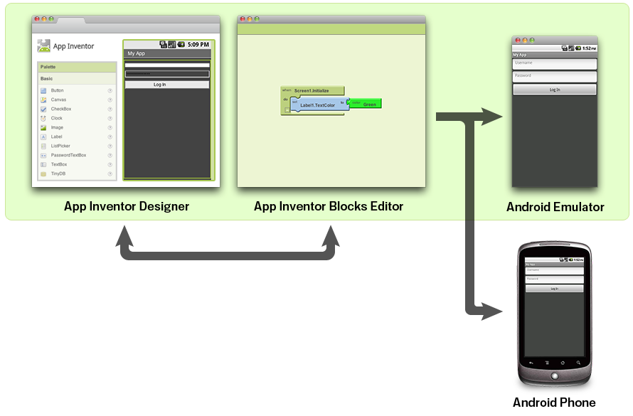
The app which I designed on MIT app inventor is as shown below.
- The App Inventor Designer, where I select the components for my app.
- The App Inventor Blocks Editor, where I assemble program blocks that specify how the components should behave. I assemble programs visually, fitting pieces together like pieces of a puzzle.
- My app appears on the phone step-by-step as I add pieces to it, so I can test my work as I build. When I'm done, I can package my app and produce a stand-alone application to install.
MIT App inventor - Process flow and development
From the MIT App Inventor website we need to log in into the online building application by clicking the “Create apps!” button. In order to log in we need to have a Gmail account. Once we are logged in now we can create our first project.
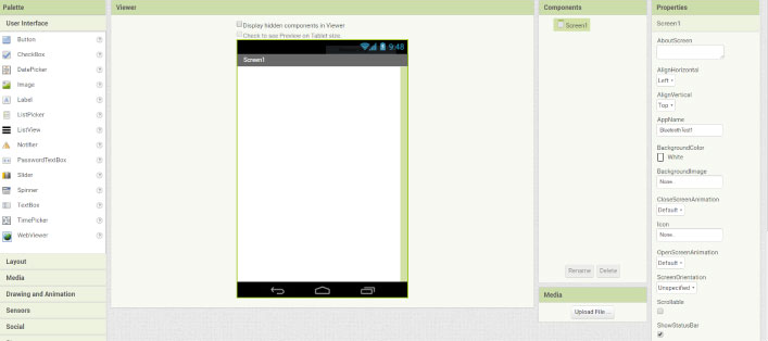
But before do that, we can connect our smartphone to this project so that we can see how the app is taking shape directly on our smartphone in real time.
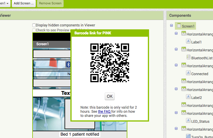
In order to do that first we have to download the MIT AI2 Companion app from the Play Store and install it on our smartphone. Then from the Connect menu from the online editor we will select AI Companion and a barcode will appear which we just need to scan it or insert the code into the smartphone app and the connection between the online editor and the smartphone app will be established.
So now for example, if we insert a button in the screen of the online editor, the button will appear in real time on the smartphone as well. Similar to this, if you don’t want to use your smartphone while building the app, you can install the Android Emulator on your computer and use in the same way. You can find more details how to set up the Emulator on their website.
First we will add some HorizontalArrangements from the layout Palette and set their properties like
the height, the width and the alignment to match our program desired look.
The image shown below is a semi finished application, which can be tested on an android phone.
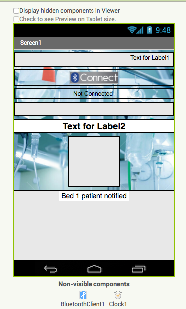
Then from the UserInterface Palette we will add a ListPicker and attach an image to it. The ListPicker will be used for selecting the Bluetooth device to which our smartphone will connect.
Next we will add another HorizontalArrangements in which we will place a Label.
This label will indicate whether the smartphone is connected or not to the Bluetooth module and
that’s why we will set the initial text of this label to “Not Connected”.
The next label will be used for displaying the status of the LED, whether is turned off or on.
The initial state will be “LED: OFF”.
Next we will add the two buttons, ‘Turn On’ and ‘Turn Off’ for controlling the LED. I am trying to develop a sensor & notification device, which will notify the nurse and the hospital administration desk, whenever an IV bag at bed number “x” is empty.
At this point it is good to rename the components so that we can easier recognize and use them in the Blocks editor later. What’s left now is to add the BluetoothClient which is a Non-visible component as well as a clock which will be used for the real time indication of the connection status.
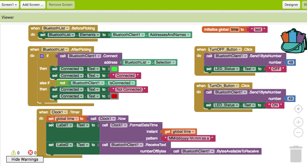
Blocks Editor
Now in the Blocks editor we are ready to give life to our program. From the left side we got all the blocks and function related to the previously added components.
Android App Blocks
We will start with the BluetoothList ListPicker. From there first we will add the ‘BeforePicking’ block and attach to it the ‘set Bluetooth Elements’ block. Then from the BluetoothClient blocks we will add the ‘BluetoothClient AddressesAndNames’ block.What this set of blocks will do is set a list of Bluetooth devices which are already paired with our phone so when we will click on the ListPicker “Connect Button” the list of all paired devices will show up.
BeforePicking Block
Next we have to set what will happen after we will pick or select our particular Bluetooth module. From the BluetoothClient block we will add the ‘call BluetoothClient .Connect address’ block and add the block ‘BluetoothList Selection’ to it, which means that our phone will connect to the Bluetooth address that we have previously selected.
AfterPicking Block
Next from the Clock blocks we will add the “.Timer” block. Within this block we will make the real time indication whether the phone is connected or not to the Bluetooth module using the “set Text” block of the label named “Connected”.
Clock Block
Next we need to give life to the two buttons. So when the “TurnOn_Button” will be clicked we will use the Bluetooth client function “Send1ByteNumber” to send a number to the Arduino Bluetooth module. In our case that’s the number 49 which corresponds to the character ‘1’ according to the ASCII table and that will turn on the LED. Right after that we will use the “ReceiveText” BluetoothClient function to receive the incoming String which is send back from the Arduino to the phone. This String is set to the “LED_Status” Label.
Buttons Blocks
The same procedure goes for the “TurnOff_Button” where the sending number should be changed to 48 which corresponds to character ‘0’. What’s left now is to download and install the program on our smartphone. We can do that from the “Build” menu by either saving it to our computer and then transfer to our phone or scan a QR code for online download of the program.Mobile app developed on MIT App inventor
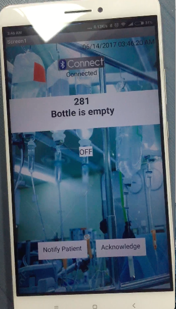
The mobile app's first look is shown below. the app had two buttons to notify and acknowledge the patients. So that the patients are aware that the nurse has seen their request and then she/he can acknowledge the same by pressing the button. The LED turns ON as soon as the nurse clicks the notify button. Once the nurse reaches the patient and treats him she can press the acknowledge button, which will notify the hospital admin desk that the nurse has attended the patient.
Please find below the original files which you can download and try it out:
Downloadable file: PINK.aia
Downloadable 123d file: PINK.apk
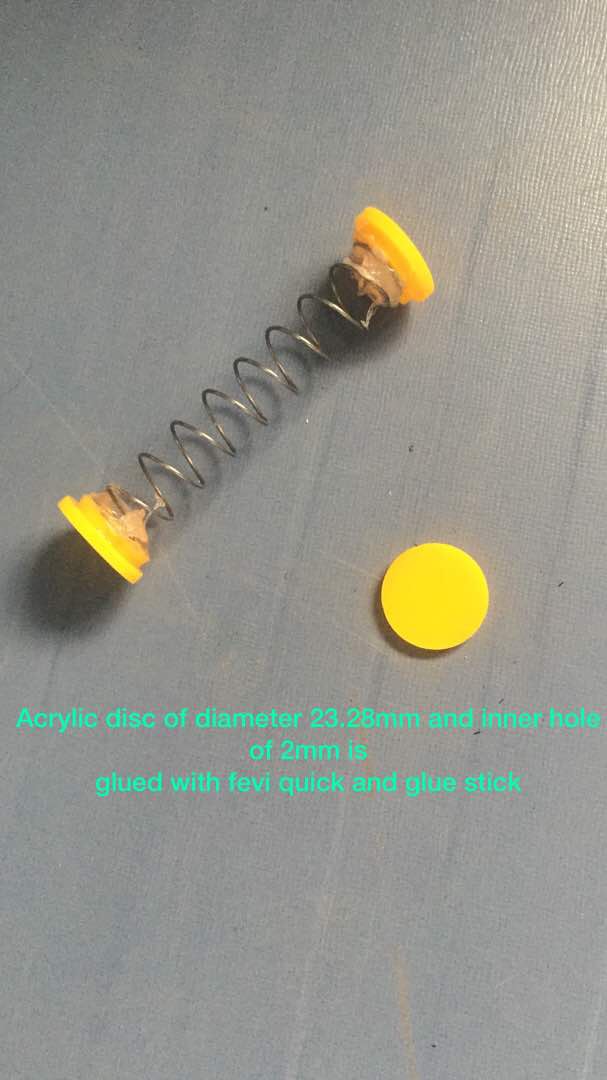
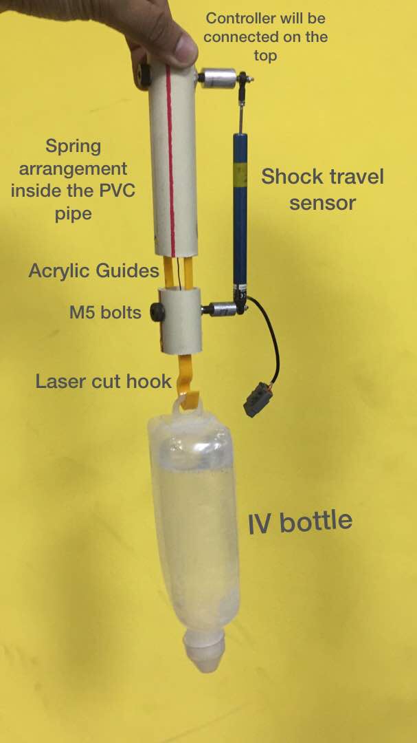
Spring arrangement
I used a spring from a damaged desoldering pump. The spring was capable enough to take the load of the IV bottle. I sketched an assemble, which will actually push the spring down and once the bottle is loaded on the stand. I cut an acrylic sheet in a circular shape. I stuck two such pieces on each side of the spring. I connected a string to both ends of the spring, which passed through the center of the spring.
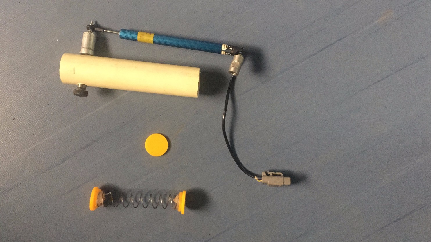
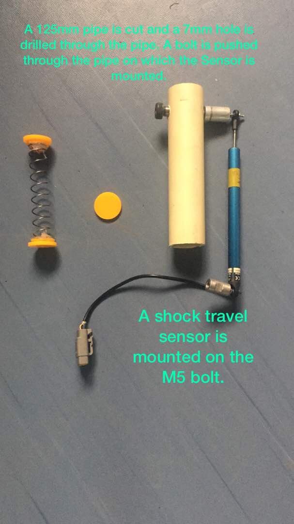
Spring arrangement with shock travel sensor and the pipe assembly
Details about Shock Travel Sensor:
- This 8" travel sensor will measure suspension, shock travel, throttle or virtually any motion (straight line) on the weight of the bottle, when mounted on the IV stand.
- This is the Penny-Giles shock travel sensor used by most professional motor sports teams. Extremely durable sealed to IP66 standards.
- Includes setup instruction for DL-32 & AuxBox.
- Body diameter .750"
- Compressed length (rod end centers) 14 3/4"
- Extended length (rod end centers) 22 3/4
- 0-5 Volt works with any data logger!
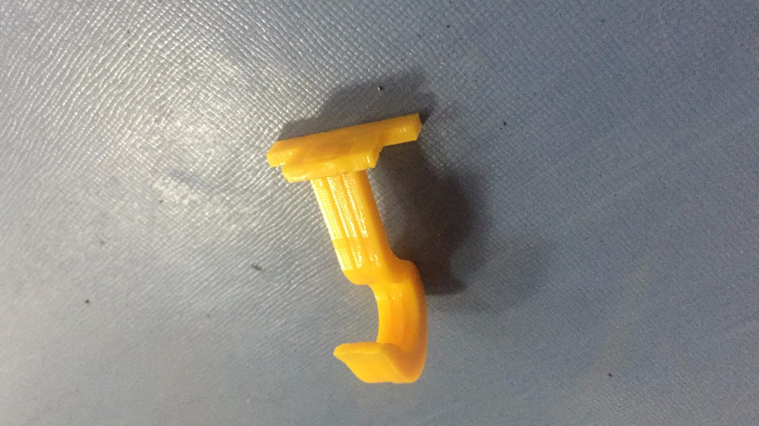
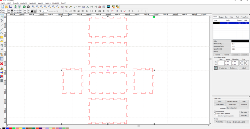
I designed the hook to hold the IV bottle . The dimension of the hook is 500mm (length) x 30mm (breadth)x 50mm(height) where.
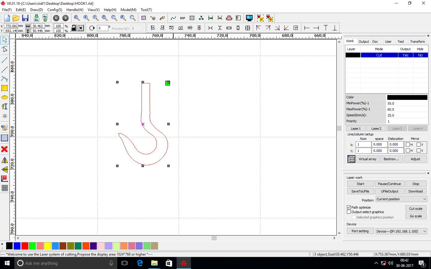
I laser cut 3 pieces of the hook and then stuck them together.
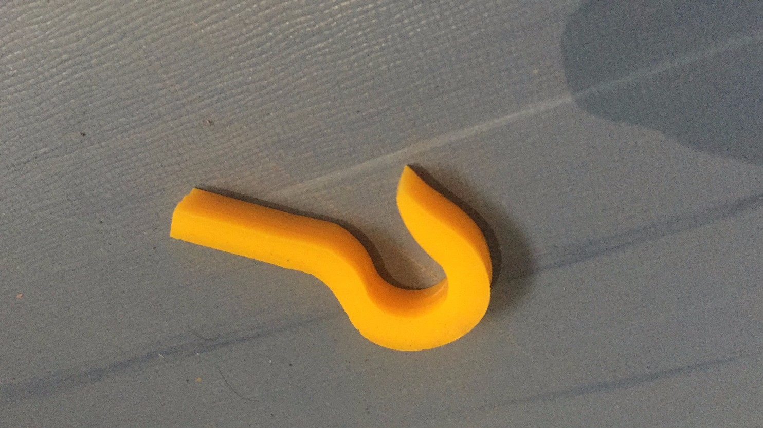
Downloadable file: Hook
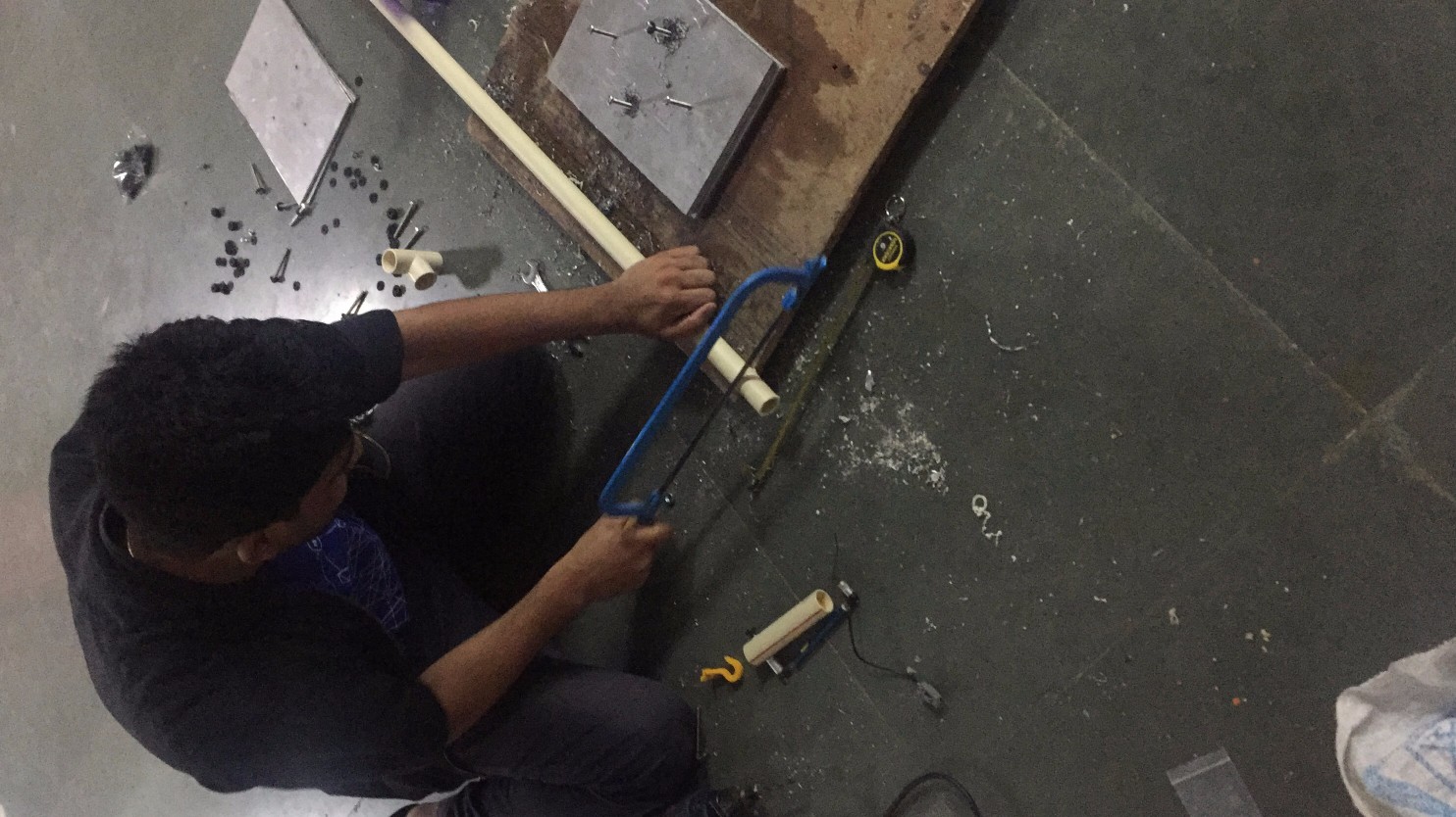
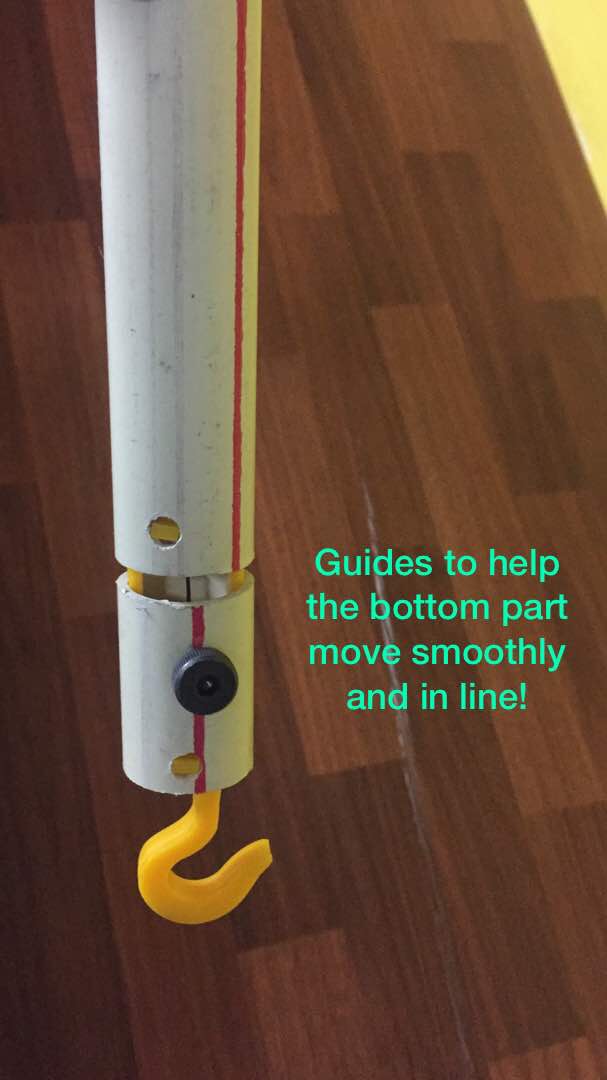
I cut another small pipe, in which the hook would be mounted. I drilled a through hole through the pipe, in which I pushed an acrylic rectangular block (block2), which acted as a bolt.
I cut two acrylic small blocks : block 1 to press fit with the hooks and acrylic block 2 (250mm x 50mm) acted like a bolt, which went through in the pipe.
Block 1: Dimension of the hole in block 1 is equal to the (breadth and height of the) glued hooks dimension, so they can press fit. The hooks will be pushed in this block 1 and then glued.
To press fit the hook inside the box and glued it using Feviquick
Block 2: I made a square hole of size 2mm x 2mm on block 2 so that a the wire can pass through it. The wire is of 28 gauge and capable enough to bare the weigh of the IV bottle. this block had a small hole through which the wire would pass.
Block 1 will be then glued to block 2 as shown in the image below
The image below shows the first try of assembling the parts together and testing it. I held it with my hands and tried to see whether the spring is able to hold the IV bottles weight.
I used two acrylic thin bars of dimension 200mm length x breadth 50mm x width 50mm These acrylic sheets acted as guides and helped the pipes to stay in the course, so that whenever the spring compresses or expands it moves in a linear pattern.
I assembled the project and started testing the device and collated reading from the bluetooth module.
Electronics of my project:
Firstly I started the machine and connected to server.
Then I followed the following steps:
1. I loaded Fabmodules.org on my browser.
2. Uploaded the .png image
3. Inverted the image.
4. Went to output format.
5. Selected the Roland mill(.rmi)
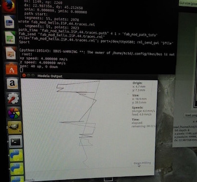
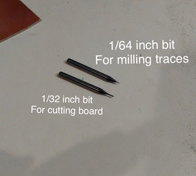
6. Then selected the PCB traces 1/32 inch bit for cutting out the board and 1/64 inch bit to mill the traces.
7. I took a single sided PCB, stuck a double sided tape below it and I pressed it on the bed on the desired position.
8. On the milling machine I pressed the View button and Set X,Y and Z to 0(zero) mannully.
- Bit Adjustments:
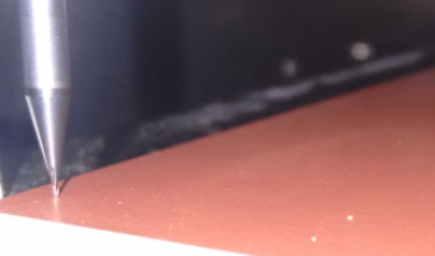
9. So now every thing is set as default. (cut depth 0.6mm, pcb thikness 1.7mm)
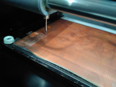
10. Now the pcb is done, but its very tedious to remove the pcb from the bed. I used a blade to chip it off.
11. Then I collected all components and started the soldering, using the Weller soldering station and set the temperature to 450 fahrenheit (232 celsius).
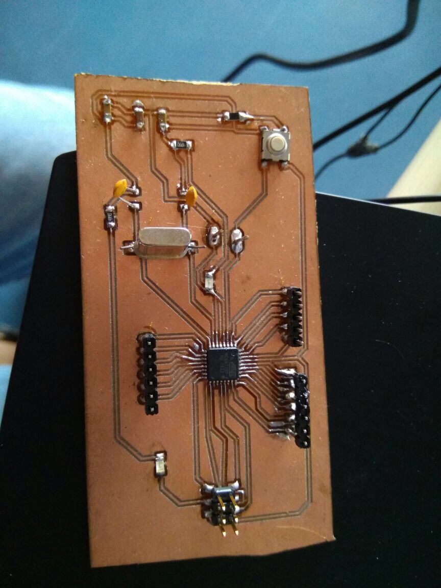
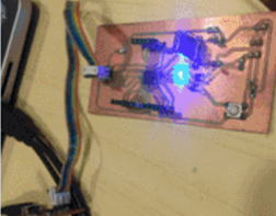
I tested the board and it was working fine with my bluetooth module HC-05
I was getting data on the mobile application I developed with the help of app inventor.
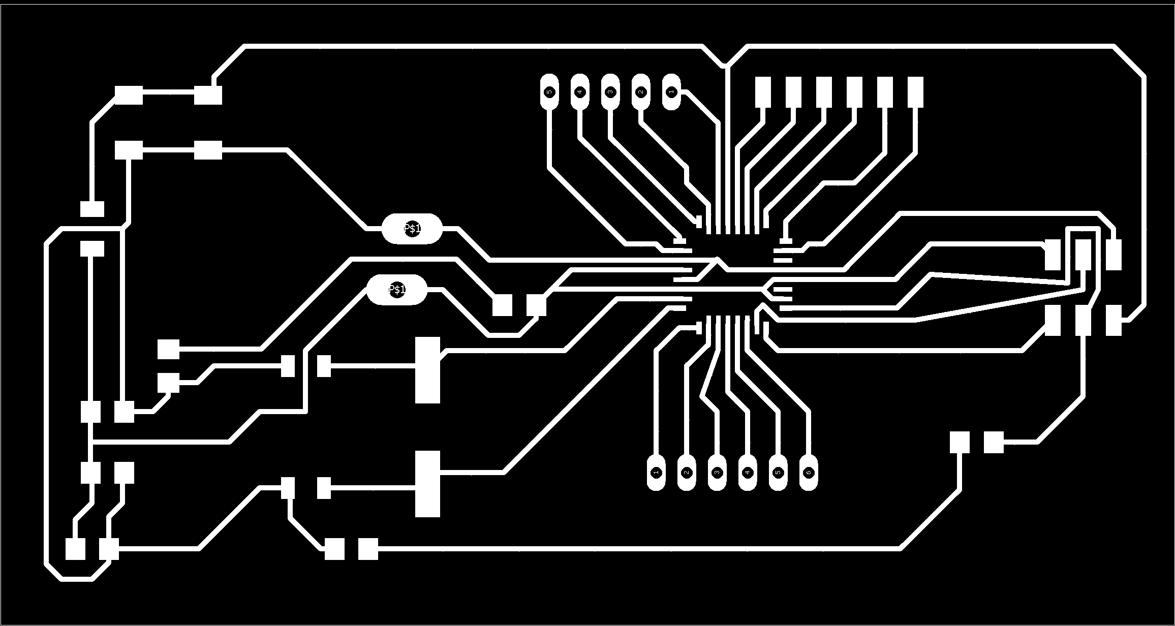
Final Board designs:
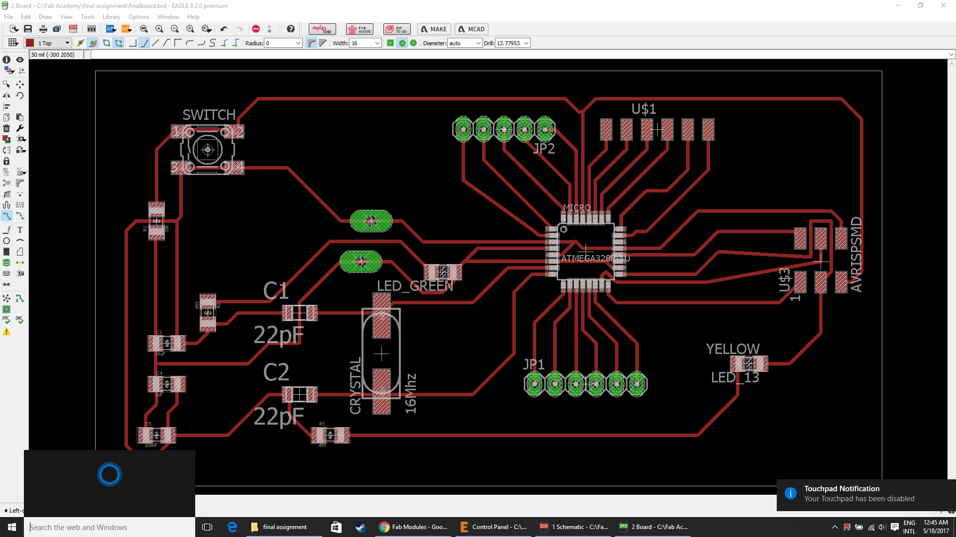
Downloadable file: finalboard.brd
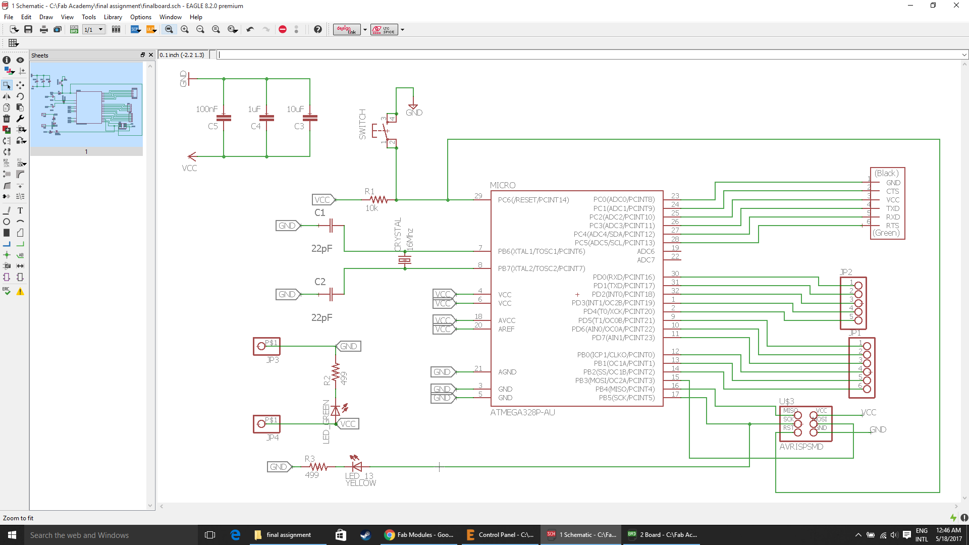
Downloadable file: finalboard.sch
Battery

I wanted the circuit to be stand alone. I will be using a lithium polymer(LiPo) battery, because it has smaller, lighter form factor and power density is quite high compared to commercially available battery technologies. The battery will be using the boost circuit as the single cell of the LiPo's rated voltage is 3.7V and I have EM18 which needs 5V for it's operation.
I coded my board using the Arduino IDE and successfully tested it.
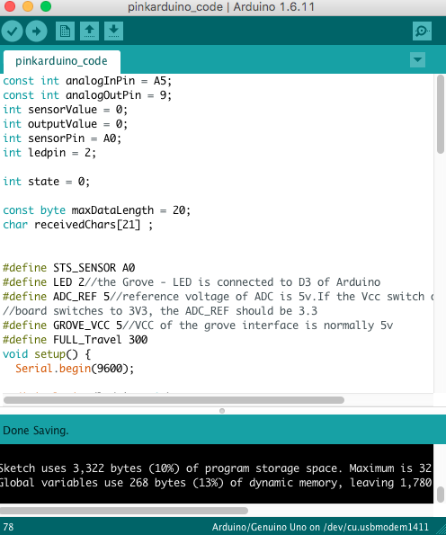
Downloadable file of the Arduino code for my final project
Casing design files:
I made the casing design on inkscape, which is as shown below.

Downloadable file: finalprojectcasing.svg
Speed: 40, power: 60, Acrylic sheet thickness: 4mm
I am using a SIL laser cutting machine. In the SIL manual, I've found they recommend the following balances.
- Acrylic etching - high speed, low power (easy to cut) High power has the potential to distort the acrylic.
- Acrylic cutting - low speed, (relatively) high power.
Also, I referred my previous assignments, where I cut acrylic of thickness 4mm.
I laser cut the files on our SIL laser machine, with speed 40 and max power at 60.
I successfully tested my kit and I presented it.
I am currently am focused to deploy this kit and get a feedback from my end costumer i.e the hospitals who have agreed to test my prototype. Parallely I will keep on working on the design and the casing of the device.
References:
- License, Registration and Approval of medical devices in India
- Regulatory guideline for Medical devices in India
- Medical devices rules
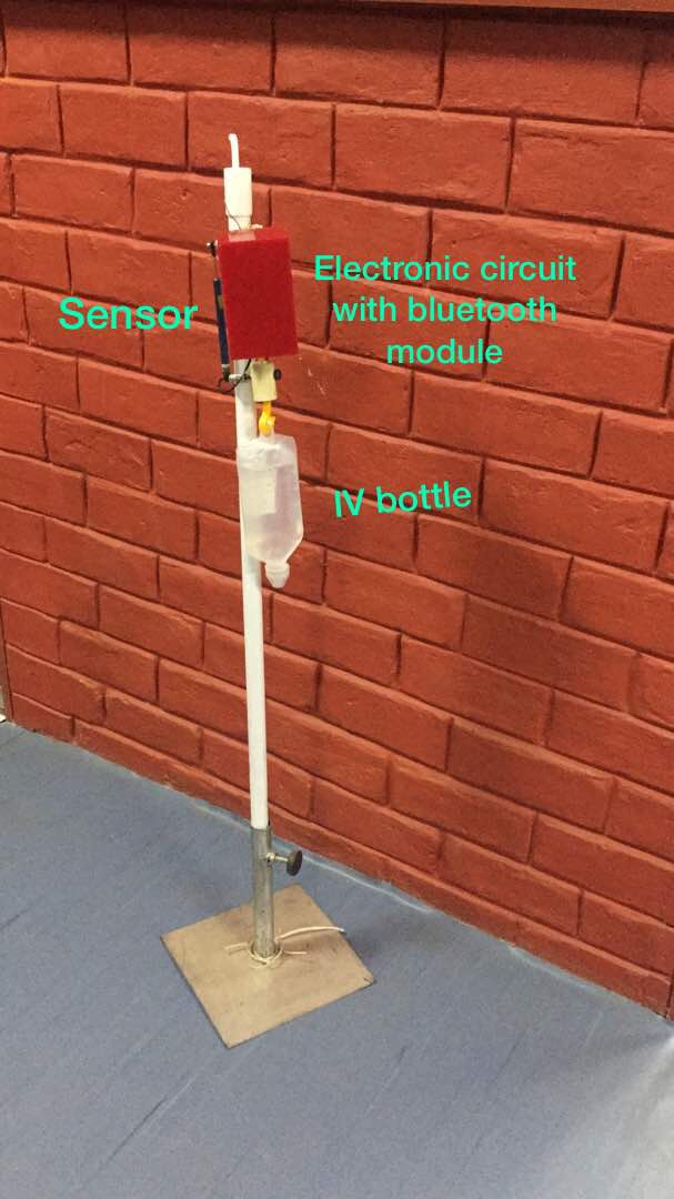
The final assembly with the IV Stand
Video
- Download the demo video
Poster

This work is licensed under a Creative Commons Attribution-NonCommercial 4.0 International License.