Assignment 9 & 11
3.4.17Mechanical Designing
Objective of this weeks Assignment
Brainstorming
We brainstormed about various problem statements / opportunities.
It was discussed that we make a machine which can make sketches using a pen, but later we realised that there are several similar projects.
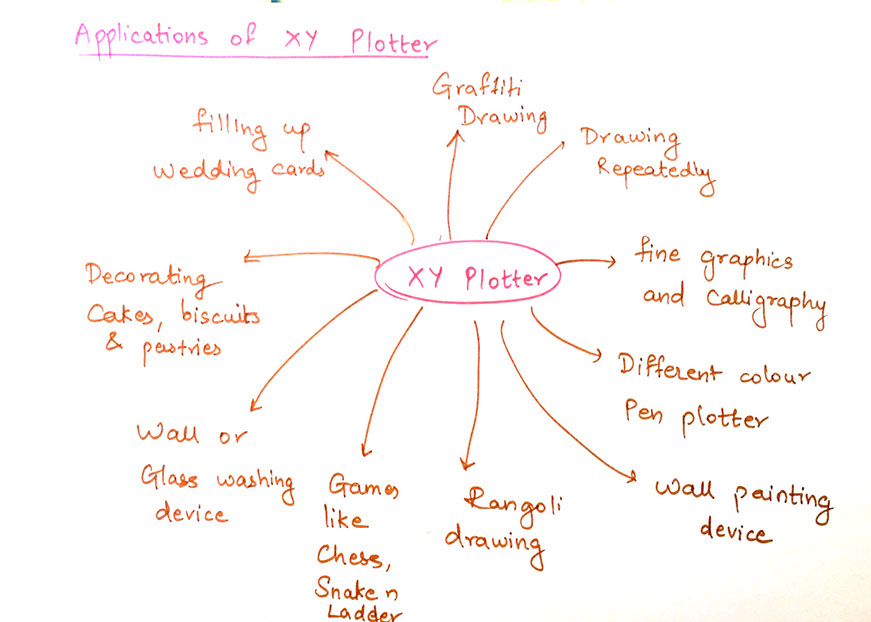
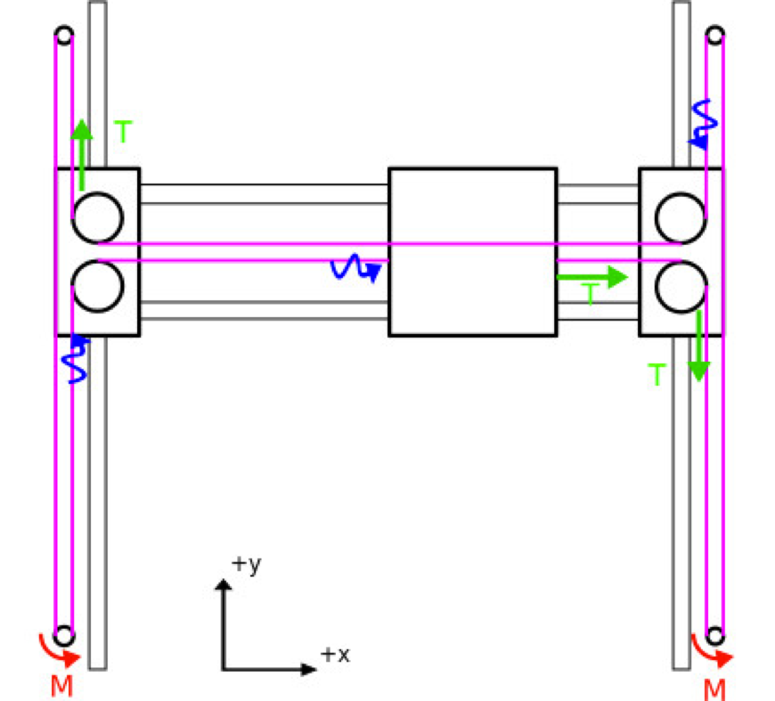
At riidl fablab we have a autonomous chessboard, which is one of the most advanced chess boards in the world. Seeking inspiration from the same, we decided to make an XY plotter, with the H Bot mechanism.
We decided to make a xy plotter with a mounted pen, which can doodle.
Also, we could learn to explore various aspects of Machine designing and programming while making this project.
We all designed all the components and parts and had a clear understanding of what we are making and how we will do it.
Later we decided to start working as a system and the flow of work is as following:
Making a basic design and structure of machine
Figuring out the material and components needed
Making a 3D model
Making a working model of machine
Making it automated
Final testing and video making
The following parts were listed by the team to start machine building
The Chassis design (MDF laser cut)
Two precision stepper motors
USB motor controller
Two machined aluminum winches
Crossed roller bearings, brush-lift motor, and cable guide
The lower deck with clip for paper
USB Cable
Universal input plug-in power supply
A4 Size paper
Improvements:
The position for motor needs to be calibrated to create a seamless flow, while moving the motor.
The over all structure can be more refined to allow larger scale of the machine and smoother movement.
Also, the battery + electronics of the entire project has to be placed at a location where the motors can move freely.
Electronics Design
Previously we thought of having the machine brain as the controller board designed and the having nodes to communicates with each other to send signals here and there. Using nodes approach is really modular, means node can be added and omitted any point of time whenever is required, a very little change in code makes the system to go to next higher stage. The terminology of 'stage' means one actuator which results into one more degree of freedom considered as a stage. In our case machine is of two stage. One stage which moves the access in X direction and other in Y direction. Multiple stages means more complex machine which can handle the very complex jobs.
To respect the time frame we have decided to go with the RAMPS 1.4 board which is attached here. It is the board which has got the Arduino mega and the motor drivers on a single board which reduces the hardware complexity as well as time required for the troubleshooting the things. Board includes all the connectors for the connecting motors, end effectors and difference sensors.
Finding proper firmware for the our RAMPS 1.4 board
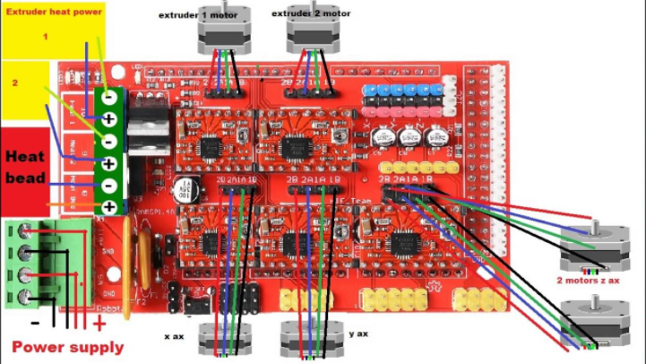
Every electronic thing you imagine there's always piece of code working on it's background which makes the machine intelligent and can handles the errors and respond them with debugging messages or the counter measures. RAMPS 1.4 is the one-stop solution for all our needs so, I was sure about the software's availability to make the system work. RAMPS 1.4 will be at the heart of the machine. It hosts the processing power and ports for required actuator actions. When we decided to go for the RAMPS 1.4, I studied the board architecture and the capabilities and the availability of the firmware for running the machine. It is one of the most popular 3D printer controller board available in the market. There are plenty of the 3D printer firmwares available which can be easily altered to make our machine work. In next week will be actually developing or tweaking the codes and burning it on micro-controllers and testing the actuators.
Downloadable files:
Downloadable file for the marlin file (marlin.ino)
Downloadable file for the xyplotter in .dxf format