Assignment 8
20.3.17Embedded Programming
Objective of this weeks Assignment
- To program the board (gaurang) and make the led on pin 7 glow
References
Reference Attiny Datasheet
How to read a Datasheet
Part number and details mentioned by the author
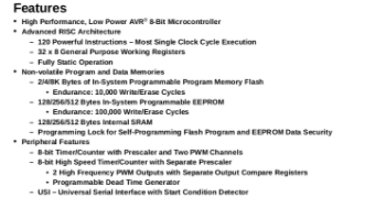
The adjacent datasheet is applicable to ATtiny modules. Also above the part number says what that part is, e.g. in here they have mentioned that it is a micro-controller and specifically it is a Atmel 8-bit AVR Microcontroller with 2/4/8K Bytes In-System Programmable Flash
Operating voltages and other vital parameters
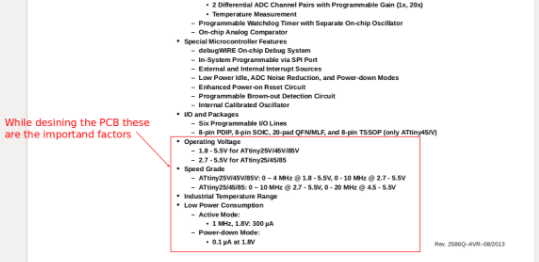
The Attiny chip designed to work between the voltage range of the 1.8V to 5.5V for ATtiny25V/45V/85V and 2.7 - 5.5V for ATtiny25/45/85. Exceeding this will burn the device. Other parameters listed under the Feature section are the RAM, ROM, Peripheral ports, etc.
Errata
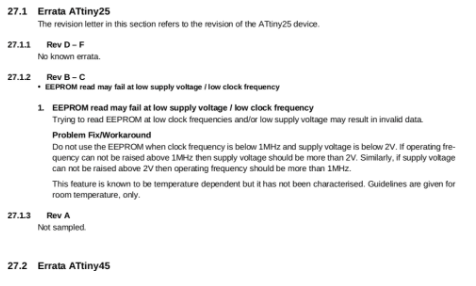
It tells us what's wrong in datasheet and it's respective revisions and suggests the methods to work around. Many a times we can't find errors, which are happening within the circuit functions even if there's no solution found in datasheet, errata is the place to look for.
Resister
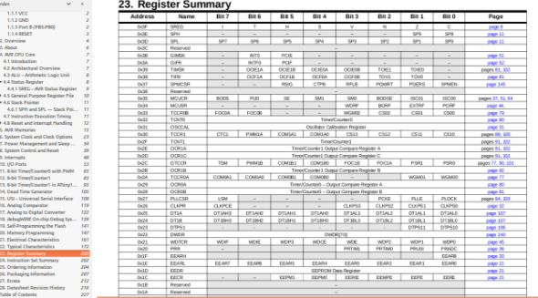
Resisters are the data holding spaces where micro-controller holds the specific data. These resistors can or can't be read or written with the content. Each resister is 8-bit long and holds the data. Some, of the resister are combined into one to hold or generate larger results. Such as 10-bit long or 12-bit long.
- How I added Attiny in Arduino IDE
In the Arduino software there is easy customization such as installing additional board and the libraries. So, I open up Arduino Preferences settings located under the Edit menu and added the Additional board URL which is given on HiLow tech website.
URL is below:
https://raw.githubusercontent.com/damellis/attiny/ide-1.6.x-boards-manager/package_damellis_attiny_index.json
Once I did that then I restarted the Arduino IDE, and then again visited the Board Manager and searched for the Attiny version of the chip availability. I found it on search result then I clicked on Download to install them.
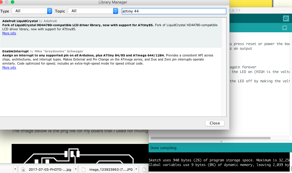
I complied my code on Arduino IDE
I added the ATtiny44 library from the Arduino IDE and then burned the code from my programmer, using the Sketch tool (upload using programmer).
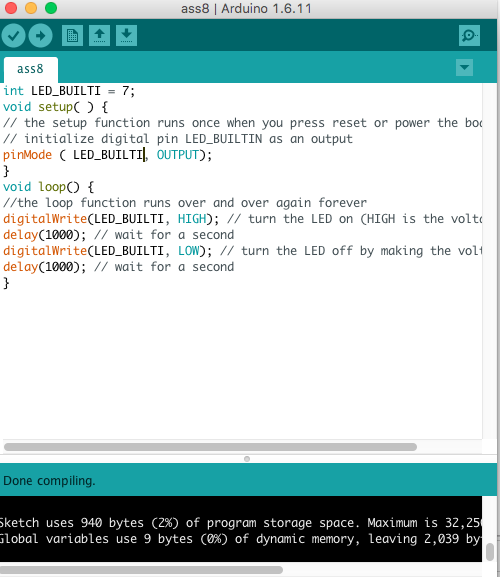
This is the program I wrote
int LED_BUILTI = 7;
void setup( ) {
// the setup function runs once when you press reset or power the board
// initialize digital pin LED_BUILTIN as an output
pinMode ( LED_BUILTI, OUTPUT);
}
void loop() {
//the loop function runs over and over again forever
digitalWrite(LED_BUILTI, HIGH); // turn the LED on (HIGH is the voltage level)
delay(1000); // wait for a second
digitalWrite(LED_BUILTI, LOW); // turn the LED off by making the voltage LOW
delay(1000); // wait for a second
}
Downloadable file for embedded programming
- In short what my program does!
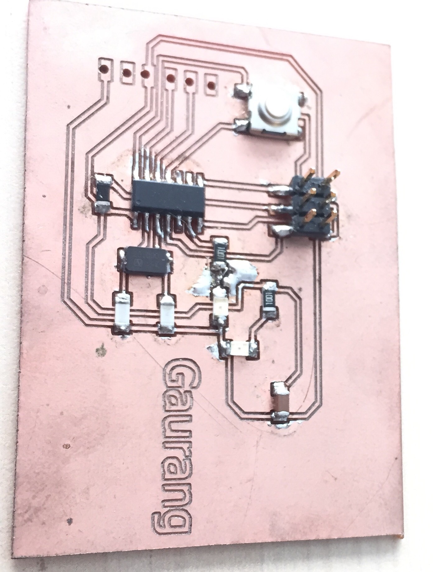
I used the Fab ISP programmer to load the code in my board. The purpose of my code was to blink the LED which I had mounted on my board. The LED will blink with a delay of 1000ms.
The image below is the png file for my board that I used for milling and stuffing.
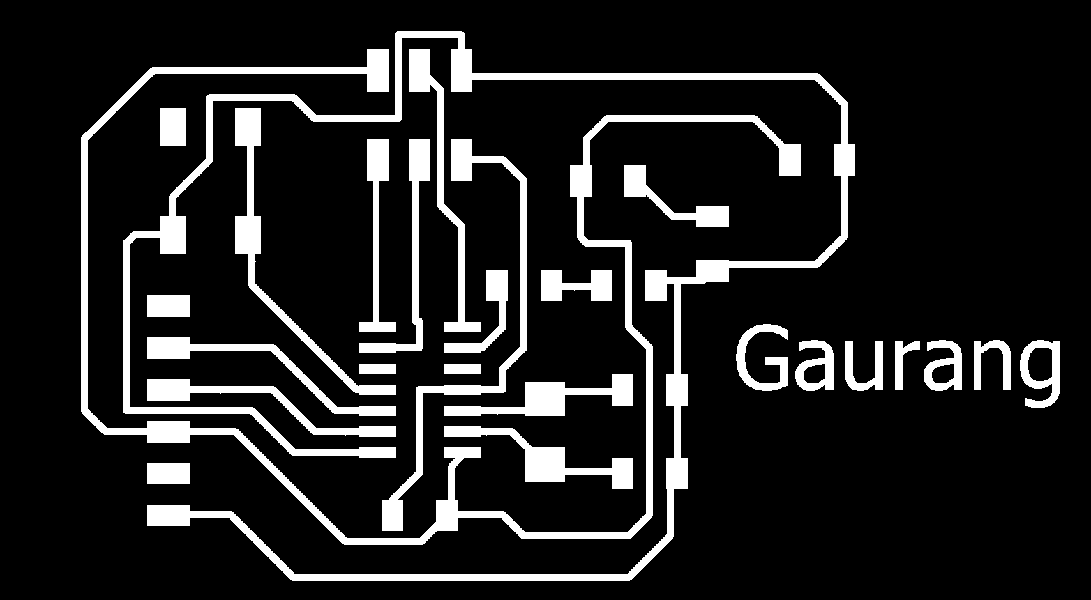
I used the same board from assignment 6 for this assignment. I programmed the board using a Fab ISP module and immediately started testing the board. I recorded a video of the testing, which is attached at the end of this assignment.
Components needed for the board:
| 1 ATTiny 44 microcontroller | 1 Capacitor 1uF |
| 2 Capacitor 10 pF | 2 Resistor 10k ohm |
| 3 Capacitor 10 pF | 1 Resistor 100K ohm |
| 1 Resistor 10K | R2 100ohm |
| 1 USB connector | LED 1 |
| 1 Cystal 20MHz | LED 2 |
| one usb mini cable | one ribbon cable |
| two 6 pin connectors | R3 100ohm |
| Jumpers J1FTDI | Jumpers J2FTDI |
Final Board designs:
Downloadable file: finalboard.brdDownloadable file: finalboard.sch

The board is working fine, as shown in the video below:
How to read SMD resistor markings ?
How to read a Datasheet?
How to read a Datasheet?