Assignment 6
7.3.17Electronic Production
Objective of this weeks Assignment
- Getting started with Eagle
Downloaded form the Autodesk Eagle WEBSITE
- Installing Eagle
- To install Eagle I used the following tutorial to SETUP
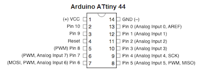
Schematic of ATtiny44
Steps for creating our own hello world circuit is as follows:
Eagle Software for designing of hello world circuit.
I use EAGLE because
Cross-platform – EAGLE can run on anything: Windows, Mac, even Linux. This is a feature not too many other PCB design softwares can boast.
Lightweight – EAGLE is about as svelte as PCB design software gets. It requires anywhere from 50-200MB of disk space (compared to the 10+GB more advanced tools might require). The installer is about 25MB. So you can go from download to install to making a PCB in minutes.
Free/Low-Cost – The freeware version of EAGLE provides enough utility to design almost any PCB in the SparkFun catalog. An upgrade to the next license tier (if you want to make a profit off your design) costs at least two orders of magnitude less than most high-end tools.
Community support – For those reasons, and others, EAGLE has become one of the go-to tools for PCB design in the hobbyist community. Whether you want to study the design of an Arduino board or import a popular sensor into your design, somebody has probably already made it in EAGLE and shared it.
1. Open the Eagle software
.png "PNG FILE")
2. Under the command button : ADD command to add the components to the design layout which is available.
.png "PNG FILE")
3. I added the ATTiny44 chip from the ADD Command option.
.png "PNG FILE")
4. In the similar fashion i added all the components such as resistor, capacitor, Leds, button, AVRISP SMD header pins,
etc.
.png "PNG FILE")
5. I used the command net to join the two components pins with each other.
.png "PNG FILE")
6. After connecting all the component with each other, to know wether all the components are connected or not with the
ERC command.
.png "PNG FILE")
7. In the Board version, after arranging the components in the proper place, then route the wire with the routing option available from the command button bar.
.png "PNG FILE")
8. Before using the route option, select the ratsnet to so that the number of wires should be reduced.
.png "PNG FILE")
9. DRC Parameter
.png "PNG FILE")
10. DRC Parameter
.png "PNG FILE")
12. DRC Parameter
.png "PNG FILE")
.png "PNG FILE")
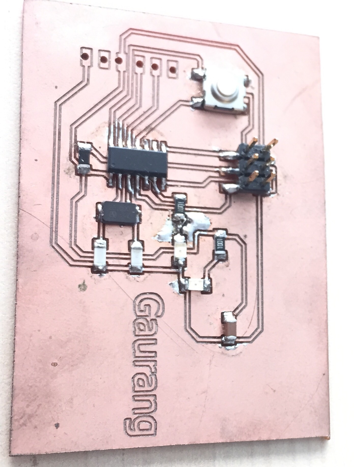
I connected a LED to pin 6 of the ATTiny44 controller, to get a feedback from the board.
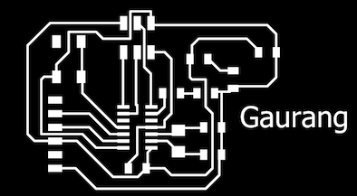
- The board looks like this!
Downloadable file for the above board in .brd format
Downloadable file for the above board in .sch format
Components needed for the board:
| 1 ATTiny 44 microcontroller | 1 Capacitor 1uF |
| 2 Capacitor 10 pF | 2 Resistor 10k ohm |
| 3 Capacitor 10 pF | 1 Resistor 100K ohm |
| 1 Resistor 10K | R2 100ohm |
| 1 USB connector | LED 1 |
| 1 Cystal 20MHz | LED 2 |
| one usb mini cable | one ribbon cable |
| two 6 pin connectors | R3 100ohm |
| Jumpers J1FTDI | Jumpers J2FTDI |
Tips for SMD Soldering
Place the IC carefully making sure the pins are lined up as well as they can be, on some of the larger pin count packages this can be a bit difficult. In some ways this can be the hardest step.
Once properly lined up tack a few pins or use a high temp adhesive like a paper tape to hold the IC in place. Were now ready to solder it!
Start by tinning our tip, clean it and fill the bevel with a bit of solder. This "pocket" of solder will glide over the pins heating them and depositing the perfect amount of solder on each one. Because of the flux, surface tension and temperature differences the solder makes very high quality fillets that usually require no solder wick as the right amount is deposited at each transition.
The key here is to make sure the is enough solder on the bevel to make good connection, but not too much to over load the "pocket". Drag time should be kept minimal but there should be enough time for a wetting action to occur. A good initial time is about 1 second per pin but this depends on a number of factors, and can be sped up. But it is a good place to start at first.
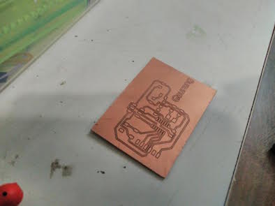
The board after soldering it.
Downloadable file: Code files in .ino format
I ran a LED blink code on the board by keeping Pin 7 as my output pin, as shown in the video below. I will share this in detail in Assignment 8:
I used the Arduino IDE and I kept a delay of 100ms for the LED blinks. My board is working and showing the desired output.
References
How to read a Datasheet?
How to read SMD resistor markings ?