Assignment 5
22.2.17
3D Scanning And Printing
Objective Of This Weeks Assignment
The objective of this week is to 3D SCAN an OBJECT
We require
I) A device to Scan the object.
Hardware Used: KINECT XBOX 360
(We will be needing Microsoft Kinect Sensor. Kinect is a line of motion sensing input devices by Microsoft for Xbox 360 and Xbox One video game consoles and Windows PCs. Based around a webcam-style add-on peripheral, it enables users to control and interact with their console/computer without the need for a game controller, through a natural user interface using gestures and spoken commands.)
Getting started: Connect Kinect to the Windows laptop (Minimum operating system requirement : Windows 8). A message will come saying device drivers not found. You can install the required software drivers for the Kinect by downloading from the internet (Kinect NUI Motors)
(Note: Kinect drivers works on Microsoft .NET Framework and hence you need to install that as well if its already not installed on your system.)
II) A software to process the scanned data and then give output in an STL format.
Software Used: SKANECT
(In simple words, the software will help us prepare a new project, Record the image, reconstruct the captured image and Processing the scanned image)
3D SCAN AN OBJECT
The images below show the steps in which I used the software to scan and later edit the scanned image.
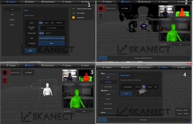
To initiate the 3D scanning there are few important things:
a. I wanted to scan myself and create a 3D model.
b. I connected the Kinect to the laptop. I used my colleagues windows laptop to get started.
c. I installed the Skanect software.
d. I also installed OpenNI for windows (32bit) and NITE (32bit). I referred a youtube video to set up the kinect. Link: https://www.youtube.com/watch?v=Rp62MUX7XTA
e. I started Setting up the kinect on a table so that it I can be in its frame (bounding box), during the scanning process.
f. I used a rotating chair to record my 3D image, using the skanect software.
g. I positioned my self looking at the colour of the image generated in the software. The colour of my image was light blue in colour, which is an ideal colour to get a good quality 3D scanned image.
h. I clicked record and started revolving the chair, using my toes.
i. Two rotations are sufficient to get a good 3D image.
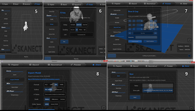
To fill the holes and make the image smooth
After doing the scan. It showed the scanned 3D image, which was not the final output that I wanted It had lot of holes in it and needed the processing to complete the image before I can 3D print it.
In Skanect there are options to fill holes in the scanned image. So I selected fill holes in that there were varius options after trying all the options I selected Strategy : Closed Hull, Smoothing : Medium (If I select High smoothing then small shapes like ear and nose will not come properly) and applied the changes.
Inisde the process tab: In the Mesh menu, I clicked the watertight option and select the smoothing to be low and run it.
Go to the geometry tab
I clicked on fill holes and selected the Opened Hull option in the strategy section and the low option in the smoothing section.
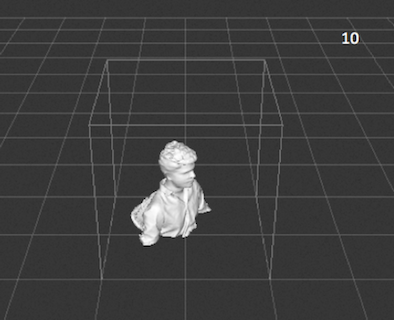
MOVE and CROP
The image was arranged at the desired position and cropped as desired. Unnecessary parts were cropped to get a cool 3D model.
Saving and Sharing
- In the share tab click on save to save the 3D model and I clicked on export to get the .stl file for 3D printing it.
Video setup for 3D scanning
video
3D model of the scanned object using sketchfab
The second task of this assignment is 3D printing
- I thought to make a lamp shade. This is something I wanted to make from a long time and gift it to my wife
- In this assignment I had to design and print a 3D object that was to be made by additive manufacturing technique
Software used: Fusion 360
Object created: Lamp Shade
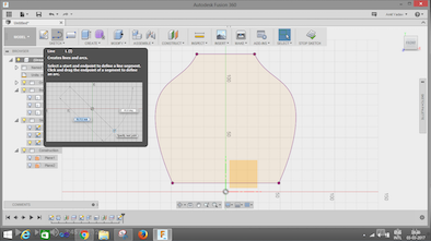
Steps:
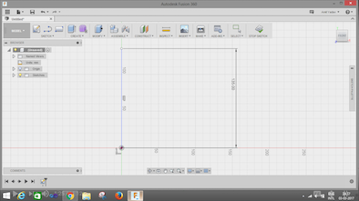
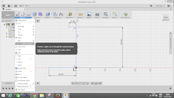
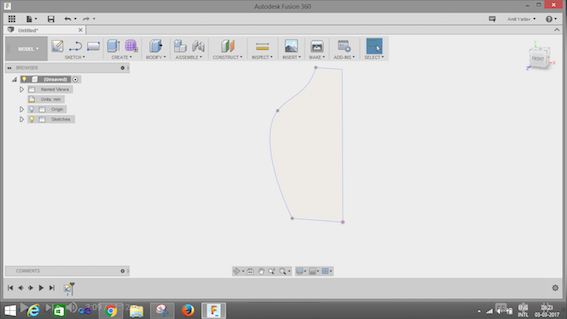
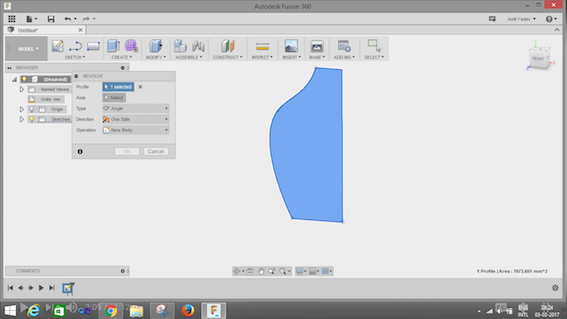
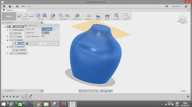
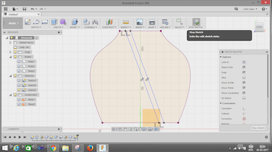
- I used line and spline options from the sketch tab to create this sketch. Dimensions : Height 135mm, Top 23mm, Base 45mm (I used the spine option to give it the desired shape.)
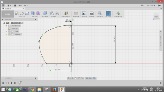
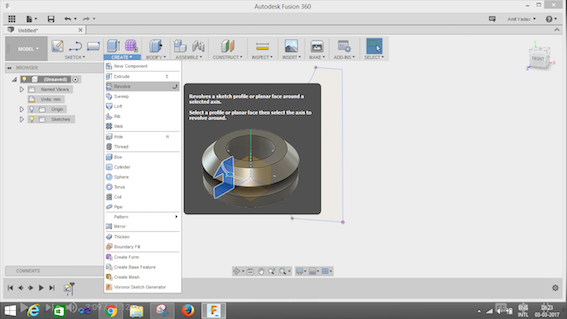
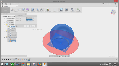
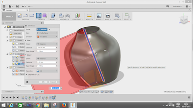
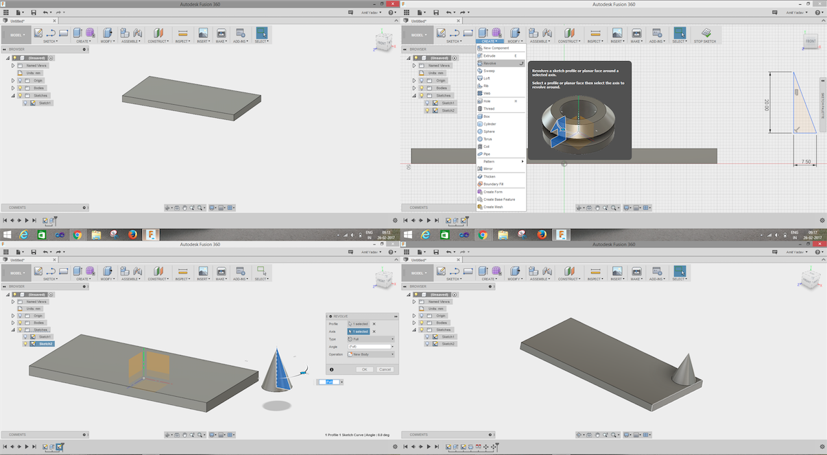
- For getting the cylindrical shape
- I used revolve button and clicked on the profile I made (highlighted in blue)
- I then selected the axis (i.e height of the object)
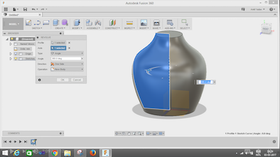
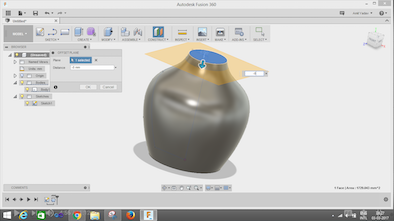
I created three parts of the object to add design to the object.
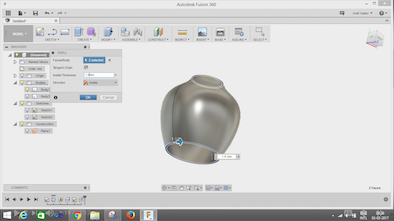
For making the body structure of the object.
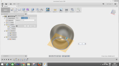
- Click on construct tab.
- Select the offset plane i.e top of the object.
- I dragged the arrow downwards (-8mm Insert this value)
- I clicked on the create tab
- Click the split option
- Select the body to be split and use the splitting tool for cutting it.
- Another body will appear. (Body2)
Click on the bulb of the body 1 and turn it off, so that we can work on body 2 To put the bulb inside we need to make a hole on body2.
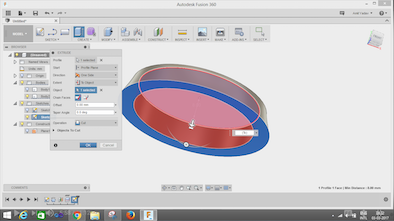
To make the object hollow for hosting the bulb -TURN ON Body1 by clicking on the bulb and turn off Body2.
- Go to the modify tab
- Click on shell
- Select the top plane, by holding the control button select the bottom plane.
- Specify the inside thickness (1.6mm)
- Click ok to see the shell.
Follow the same process to create a Body3
To Make the design of the lamp shade
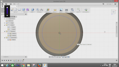
Click on the sketch tab
- Choose the project box
- Select the Geometry option
- Click on the body icon in the selection filter
- Click ok
- You will see a 2D image of the object
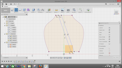
Create two lines using the line option in the sketch tab.
- To make the lines parallel
- In the sketch pallet choose the parallel button in the constrain option.
- Select the lines which are supposed to be parallel.
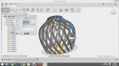
Extrude the parallel lines by selecting the profile.
Click
- Direction: Both sides
- Operation: Intersect
- Body 4 will appear after clicking Ok.
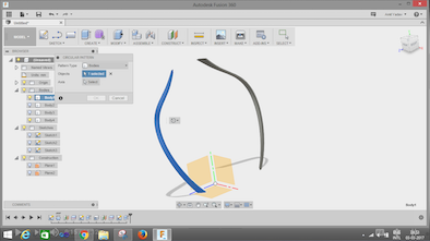
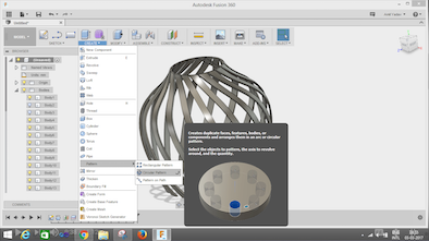
Make a pattern (There are two profiles, select one profile first and follow the steps below)
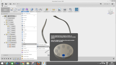
- Inside the create tab. Select Pattern
- Click Circular pattern
- Select the object
- Select the z axis
- Quantity : 18 (18 number of patterns will appear in the design)
Repeat the same process for the other profile.
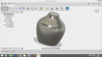
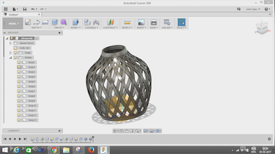
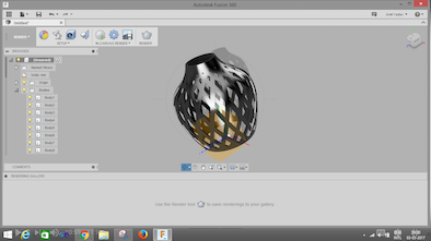
Once you turn on all the body bulbs, you will see the final object! Wola!!
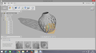
I did the rendering to give it a metallic look.
Specifications:
12% density with hexagonal infill
Material PLA
Downloadable 3D file for the lampshade
Merits of 3D printing, how it contrasts the conventional machining :
3D printing is the new trending manufacturing technology which is more efficient ,easier and a cost efficient way of getting your designs to reality. Moulding, Casting etc are the other ways of manufacturing, but 3D printing is a very efficient small scale level of manufacturing technology.
3D design allows the drafter to manipulate textures and colors of design without the use of additional resources. 3D design outputs doesn’t need a physical space for storage, and physical raw materials to execute. There are basically limitless times for revision since it doesn’t utilize physical resources (even paper and ink) to begin with.
You can print your design in a less time and with better finish, desired properties like density, material fill , pattern of fill etc. There are too many other complications making the design in conventional methods as we require to make a core, mould, getting appropriate material and conditions of temperature and pressure is a tougher task. 3D printing happens at normal conditions and is a very efficient printing process. There is no necessity of post machining process once your model is ready. You've greater surface finish and more durability depending on what factors you desire to adjust. Looking up at all these points 3D printing looks like a very efficient and a meritorious way of manufacturing.
In short Advantages can be written as below:
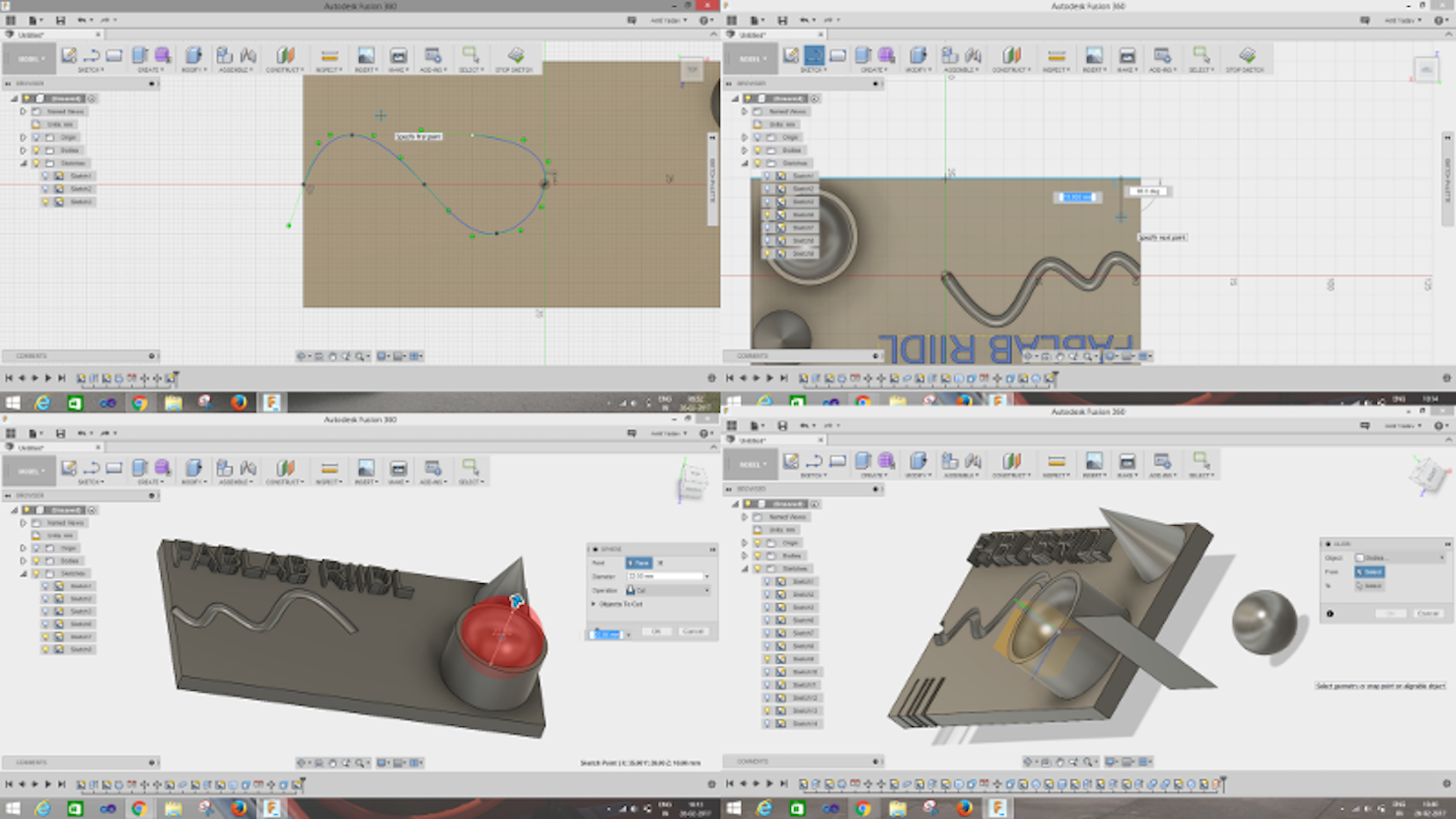
TASK 3 : Test the design rules for your printer(s) (group project)
For the group project we decided to make different cutout shapes, extrude, hollow, sharp things to know how 3D printer performed. Sketch is shown in the below image.
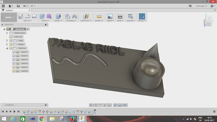
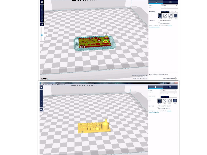
Images shown below describe how the sketch is constructed.
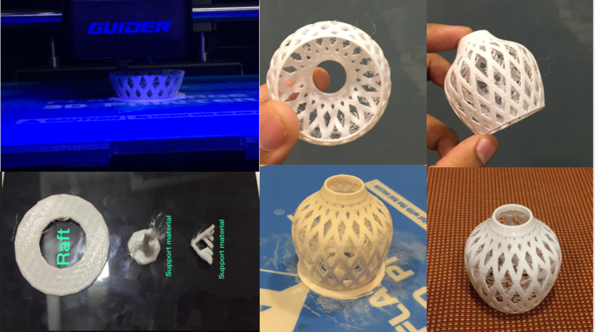
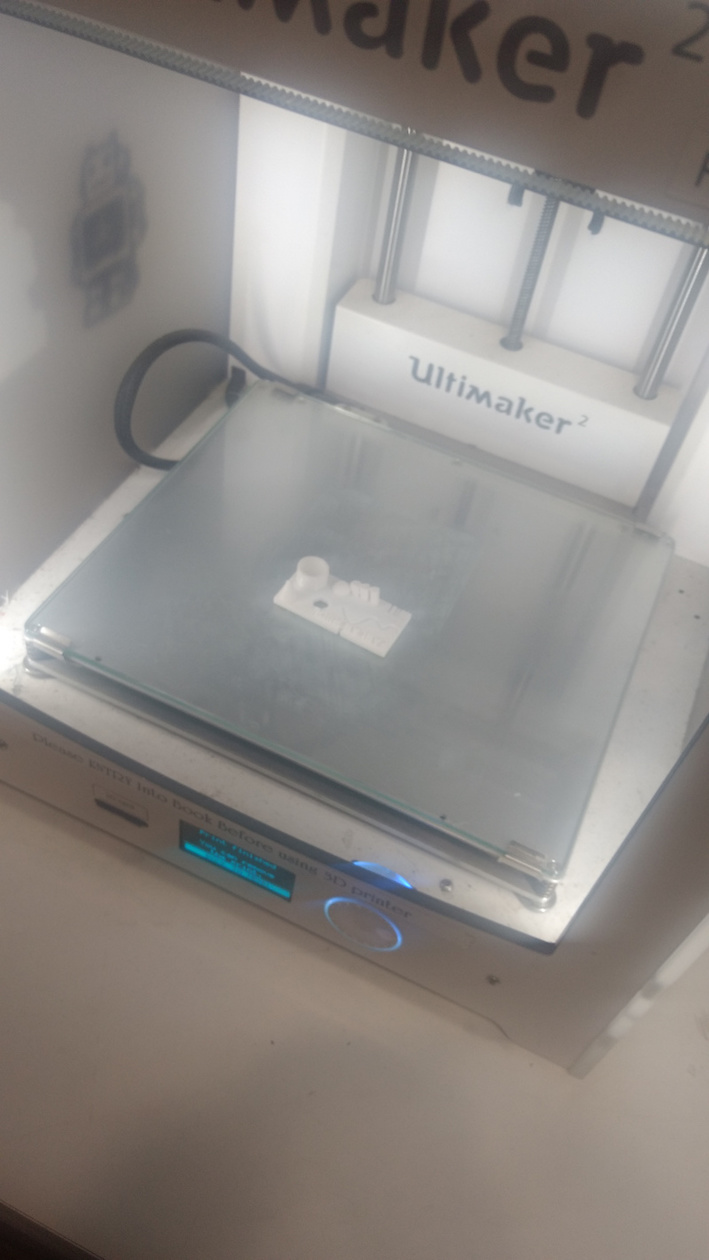
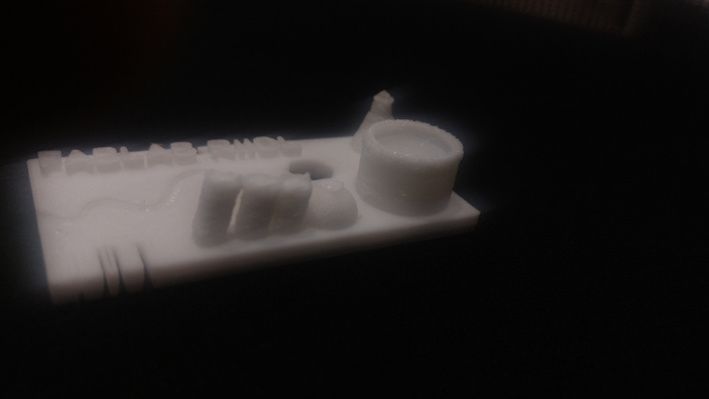
After 3D printing :
Please find below the downloadable files of the above designed objects:
Downloadable file in .stl format
Downloadable file in .mix format
Downloadable file in .brd format