Assignment 4
15.2.17Electronic Production
Objective of this weeks Assignment
The aim of this week assignment is to make a Fab ISP Programmer. So, in this assignment I’ll be milling the PCB and will be stuffing the board with SMD components.
Knowing about FABISP
The FabISP is an in-system programmer for AVR microcontrollers, designed for production within a FabLab. It allows you to program the microcontrollers on other boards you make.
For PCB Selection
Printed circuit board is the most important part of electronics. Alternately, the acronym has also accounted for printed wiring boards and printed wiring cards, which are essentially the same thing.
The composition of a PCB generally consists of four layers, which are heat laminated together into a single layer. The material used in PCB includes the following layers from top to bottom:
• Silkscreen
• Soldermask
• Copper
• Substrate
The last of those layers, substrate, is made of fiberglass and is also known as FR4, with the FR letters standing for "fire retardant."
This substrate layer provides a solid foundation for PCBs, though the thickness can vary according to the uses of a given board.
PCB of various materials are available in market, each and every PCB are recommended for different purposes. FR-4 is fibreglass-based so, when it is milled it produces dangerous glass-shard dust, which makes it unpreferable to be milled and FR-1 being hard, flat material that consists of a thin layer of copper over a non-conductive phenolic resin makes itself quite easy to be milled on. There are varieties of PCBs available in the market. Each PCB is recommended for the different purpose. There are few grades of PCBs namely FR-1, FR-2, FR-3 and FR-4.
I used the FR-1 board to mill the PCB
To begin with
- I used the FR-1 board to mill the PCB
- I downloaded the files from here : link , which are listed under hello.ISP.44 name.
hello.ISP.44.traces.png - This file will be used to mill the traces
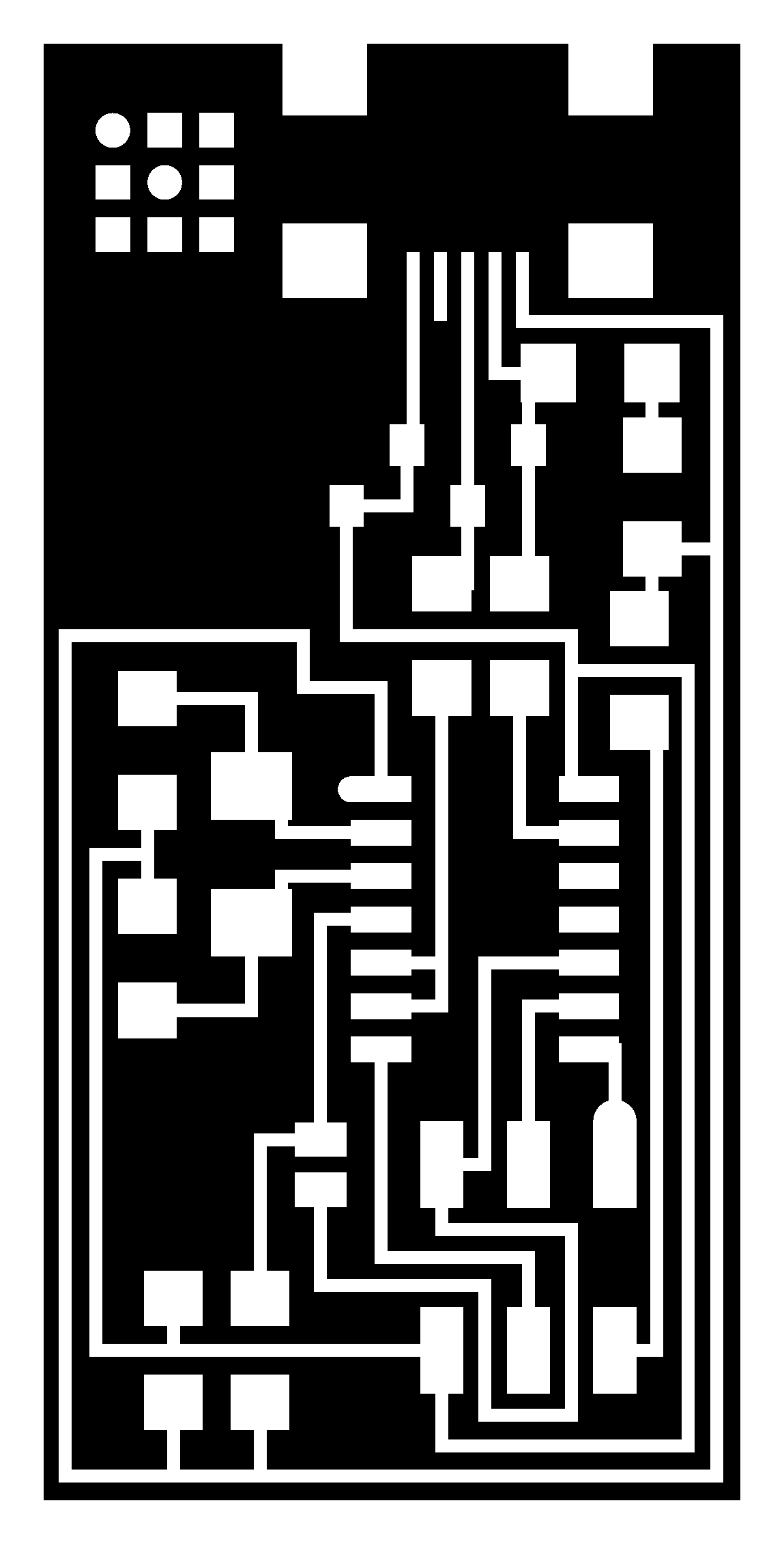
hello.ISP.44.interior.png - This file is will be used to cut-out the board from the main PC
hello.ISP.44.png - This is the file will help me to solder the components in right place
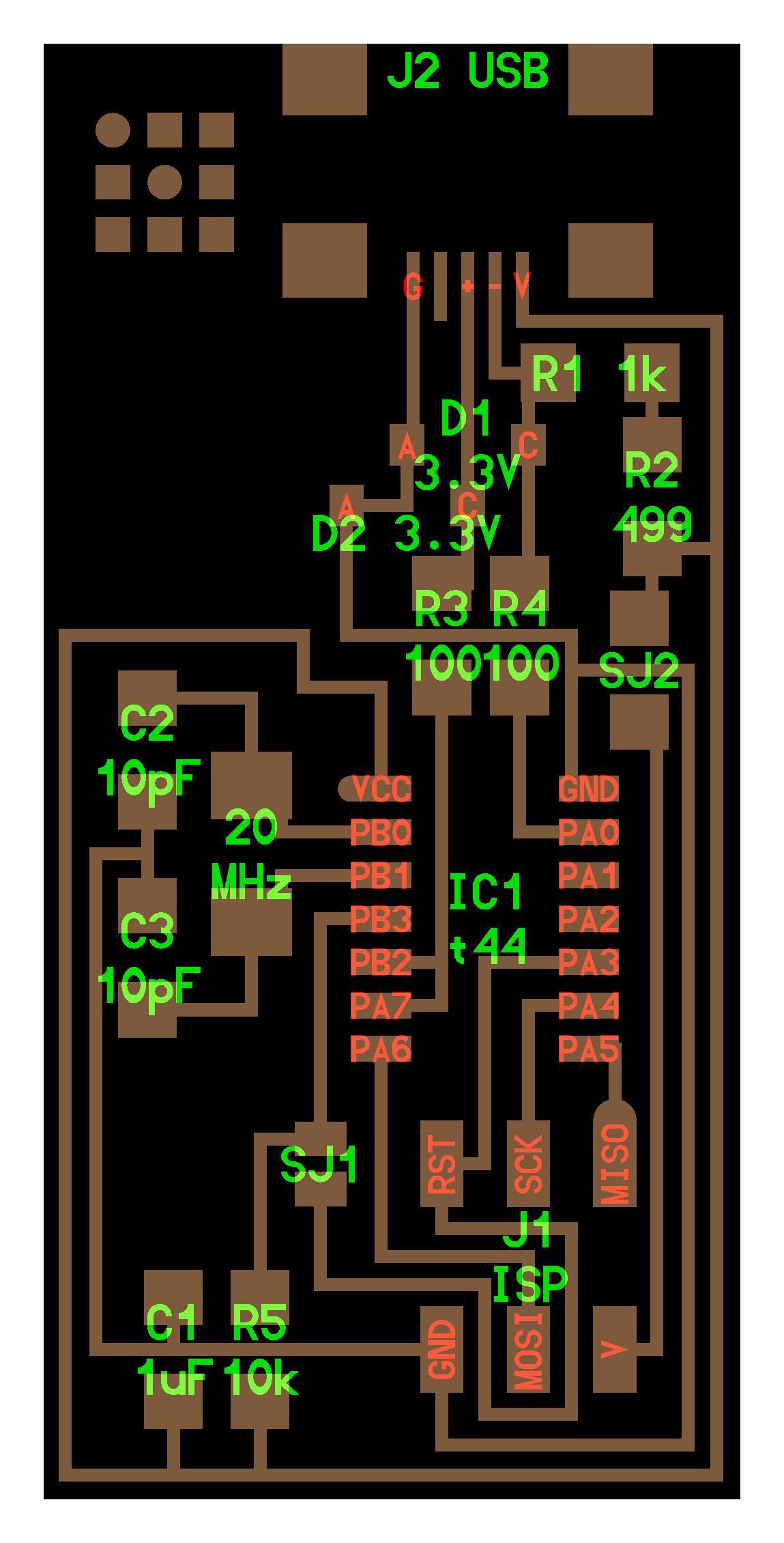
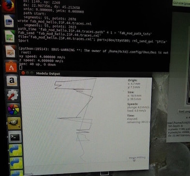
Firstly I started the Roland Modela machine and connected to server.
Then I followed the following steps:
1. I loaded Fabmodules.org on my browser.
2. Uploaded the .png image of hello.isp.44
3. Inverted the image.
4. Went to output format.
5. Selected the Roland mill(.rmi)
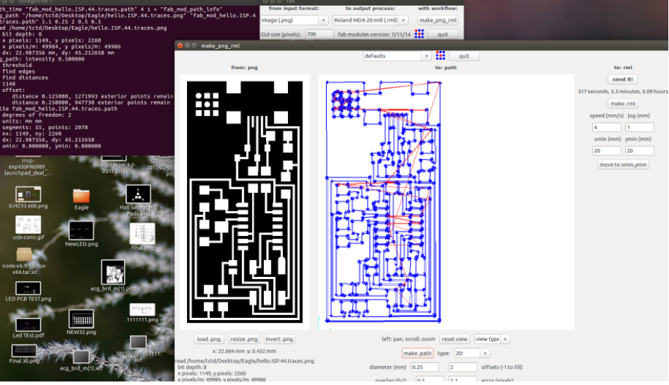
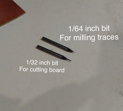
6. Then selected the PCB traces 1/32 inch bit for cutting out the board and 1/64 inch bit to mill the traces.
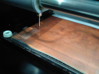
7. I took a single sided PCB, stuck a double sided tape below it and I pressed it on the bed on the desired position.
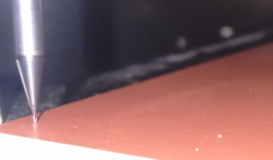
8. On the milling machine I pressed the View button and Set X,Y and Z to 0(zero) mannully.
- Bit Adjustments:
1. Insert a cutting tool in a collet.
Do not insert to the portion of an edge. When you use included cutting tool,
refer to the following figure.
2. Tighten the set screw with hexagonal wrench.
3. Click [View] of VPanel.
A spindle head moves to a center and a table moves to the front.
4. Loosely tighten the collet with cutting tool.
Insert the collet, and then loosely tighten.
5. Fully tighten the collet.
Tightly secure the collet by using two spanners.
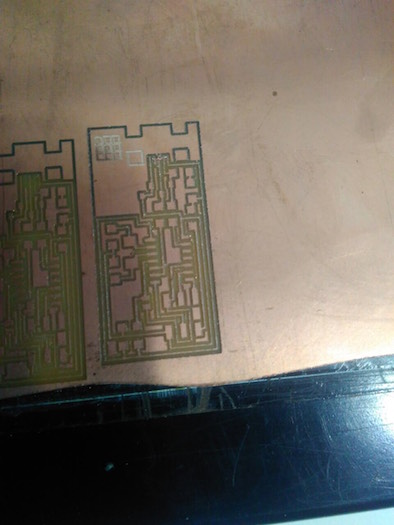
9. So now every thing is set as default. (cut depth 0.6mm, pcb thikness 1.7mm)
10. Now the pcb is done, but its very tedious to remove the pcb from the bed. I used a blade to chip it off.
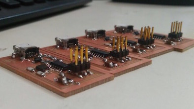
11. Then i collected all components and started the soldering, using the Weller soldering station and set the temperature to 450 fahrenheit (232 celsius).
12. Components needed for the board:
| 1 ATTiny 44 microcontroller | 1 Capacitor 1uF |
| 2 Capacitor 10 pF | 2 Resistor 100 ohm |
| 1 Resistor 499 ohm | 1 Resistor 1K ohm |
| 1 Resistor 10K | one 6 pin header |
| 1 USB connector | 2 jumpers - 0 ohm resistors |
| 1 Cystal 20MHz | 2 Zener Diode 3.3 V |
| one usb mini cable | one ribbon cable |
| two 6 pin connectors |
13. Since, I have done my bachelors from electronics engineering, I had some prior learning to do SMD soldering.
Note: Always deposit a tiny amount of solder material on the node you wish to solder. Connect the lead of the component to the deposited solder and touch the soldering ion to help them melt and merge.
One can use tweezers for placing compenets on pcb board with help of a helping hand. I use a double sided tape to get the work done.
14. Then I referred tutorials and connected the AVR Programmer "avrusb" for programming.
Programming my FabISP
To program my FAB ISP I used Ubuntu, I prefer Linux Mint but Ubuntu works well and that's what we had on the computers in the lab. If you are using a new programmer like the Atmel ICE , avrdude will probably not recognize your device. That meant I had to update AVRDUDE, so in terminal I typed "sudo apt-get update". After the update simply restart your computer to apply the updates and AVRDUDE should recognize the new device, if not simply download the newest version of AVRDUDE using terminal commands.

Note
To program the FabISP, you first need to install the necessary software for your operating system and download the firmware.
For Mac OS Software Installation we have to Download and Install Crosspack AVR - Has an installer. Url : http://www.obdev.at/products/crosspack/index.html
Just double click on .dmg file.
15. Started Terminal and typed sudo apt-get install flex byacc bison gcc libusb-dev avrdude and run it.
- Get Make (via XCode). As Xcode was already installed on my Mac had nothing to do to install "Make".
Open terminal navigate to the desktop: cd desktop
Unzip the fabISP_0.8.2_firmware.zip directory: unzip fabISP_0.8.2_firmware.zip
Move into the newly created firmware directory on your desktop: cd /Desktop/firmware
- Then you edit the Makefile
Now open and edit the Makefile. For my macos I simply opened it in the Textedit.
Copied form the fabisp website : A window will open containing the Makefile. Go to the line that says: #AVRDUDE = avrdude -c usbtiny -p $(DEVICE) # edit this line for your programmer AVRDUDE = avrdude -c avrisp2 -P usb -p $(DEVICE) # edit this line for your programmer
- If using the USBtiny programmer or another FabISP
- Remove the "#" in front of the line with "usbtiny" in it
- Add a "#" to beginning the line with the "avrisp2" in it to comment it out.
- save the Makefile
Commands used for execution:
cd Desktop/fabISP_mac.0.8.2_firmware
make clean
make hex
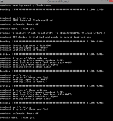
make fuse
make program
The board was not programmed, since my MAC book did not support USB 2.0 The Macbook I am using has a USB 3.0. I tried it using windows laptop to complete my assignment
Further steps:
I installed driver (AVR programmer and SPI Interface)
I downloaded the FabISP Firmware
I extracted it on the desktop and updated the driver software.
I selected, Update driver software and navigated to the place where the fabISP files are stored.
I connected the target device to the programmer.
Got to command prompt, to check whether my device is in working condition
I wrote this command on command prompt #AVRDUDE = avrdude -c usbtiny -p t44 (here c means the programmer and p means the target device)
Once you press Enter You will see this screen
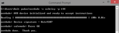
It means your device is working correctly.
Now I decided to program it.
In the fabISP folder we have a makefile, which is our programmer file that we will be burnt on the board I made.
In command prompt, if we type make
You will get an error
So we need to type make program
It starts burning the programs into the board
After burning the make program on my board, to check whether the board is working fine.
-Go to device manager
-Search the USB devices for usbtiny 44
The device will pop up
Testing my fabISP
I was trying to read the arduino signature values
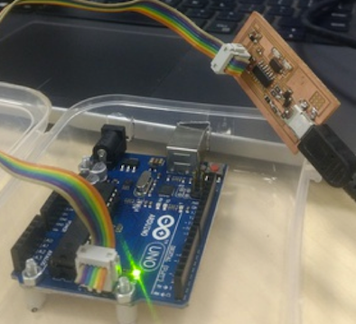
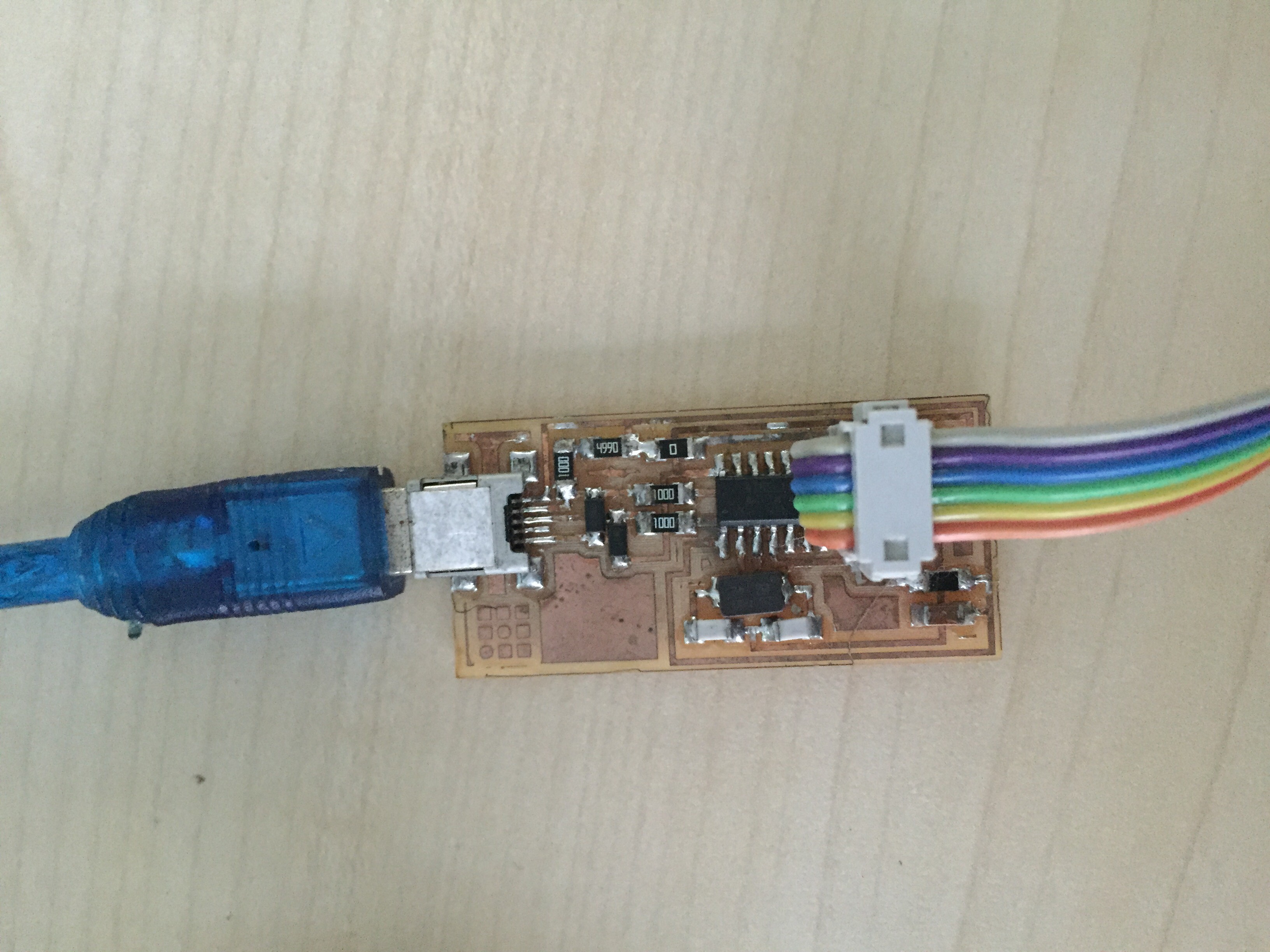
- Program the FabISP : Connected FABISP made by my lab instructor to program my FABISP. Connection : Connect both the devices using USB connection. And use FRC cable to connect my device to FABISP (already programmed device).
Now, I wrote this command on command prompt #AVRDUDE = avrdude -c usbtiny -p m328p
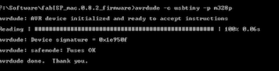
The board is ready!
References
How to read SMD resistor markings ?
How to read a Datasheet?
Milling PCBs on a Roland Modela using Fab modules