Week 3
Assignment 3
8.2.17Computer-Controlled Cutting
Getting started with Antimony and exploring parametric design.
- Since I am using a macbook pro, I was keen to use the Antimony software and start making parametric designs
- Click the window tab to select the New graph window and new 3D window
- Graph window is the one which shows you the primitives and functions which in results creation of the whole model.
- View window is the windows which actually shows your 3D model. This renders the blocks in real 3D world, which you can rotate and view the entire object by zooming in or out.
- To get started, I planned to make a trophy, where the shape of the trophy's sphere would change if I changed the height.
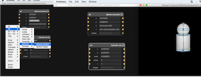
- I started by using two shapes: Sphere and cylinder.
- Right click on the graph window, select 3D and select the cylinder (Z) since we want to design a trophy. Similarly select spheres and click Sphere (center)
- I used this equation to keep the sphere above the cylinder (c0.zmax+0.8). I typed this equation in the 'z' block of the s0 sphere.
- I used this equation to reduce the size of the sphere if the height of the cylinder increases c0.r+(c0.zmin/(c0.r+2)) i.e zmin if changed it will reduce the size of the sphere. I typed this equation in the 'r' block of the s0 sphere.
- This was fun! I can simply change the values of 'zmax' and 'r' in the co block of the cylinder and see the shapes changing in the view port.
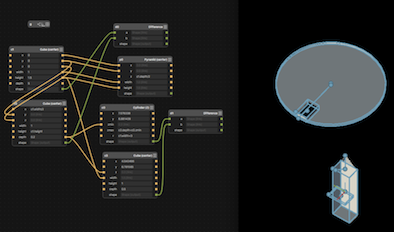
- For understanding it better and then making something on our laser cutter. I planned to make a 'top' which can spin.
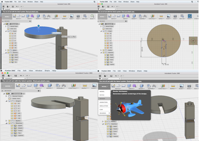
Using Autodesk Fusion 360 to gear up for my assignment - 'Making a Top"
- After the installation of the Autodesk Fusion 360 software, I saw some youtube tutorials to setup and I was good to go.
- The Autodesk Fusion 360 is much better and user friendly than Antimony. I was able to create the sketch quickly and apply all the parametric methods without much hassle.
- In my project, the width of the notch in the shaft (shaft of the top) would proportionally change with the width of the notch of the disc (circle). Also, the radius of the circle is 100mm.
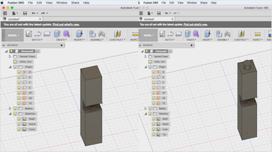
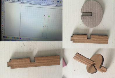
- I selected a new sketch, clicked on the desired axis I wanted to place my sketch and drew a rectangular box i.e. shaft, which is the name of the sketch in the diagram.
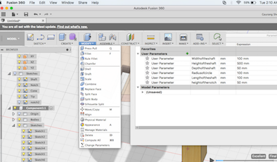
- I clicked on the modify button, then selected the 'change parameters' button to add 'user parameters' (add parameters by pressing the green coloured '+' symbol)
- I added the user parameter expressions and values as shown in the image below. and started designing the top.
Note:
- 1. For Raster/Engraving we have to select Scan width option in Object Properties and the colour can be Black.
- 2. For vector/cutting we have to select Cut option.
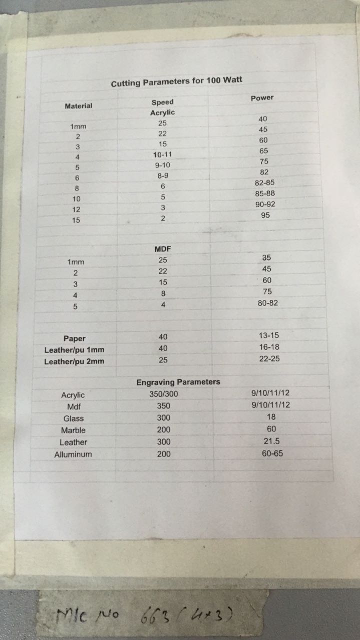
- We are using a CO2 based laser cutter, which has a 100 watt laser tube. 'SIL laser cutter' is an Indian made machine. The bed size is 900mm x 1200mm. It can do cutting and engraving both.
- The power speed and other settings of our laser cutter had to be adjusted according to the material used. Configuration used: speed = 20, power = 70 and material "cardboard". Thickness of the cardboard = 5mm. Notch of Disc = 50mm, Width of shaft = 50mm
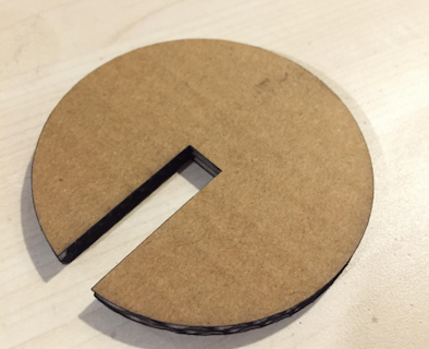
- Mistake: There were errors in the fitting, since the notch size were same. Also, the speed was slow so the cardboard got burnt at the edges. I reworked the sketch and the laser cutter configurations.
Correction
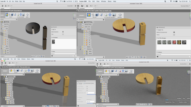
- I rechecked my design. The 3D image had to be converted into a 2D image i.e a vector file. So, I started by selecting the sketches I wanted to cut.
- I used the shift button and the mouse pointer to select the plains I wanted to laser cut.
- Once the plains are selected (highlighted in blue colour, use shift to select multiple surfaces) press 'p' and click ok in the tab which pop's up.
- To laser cut, I converted the 3D files to 2D files and imported it into 'RDworks'.
- The challenge was to save this design I created in a 'dxf' format.
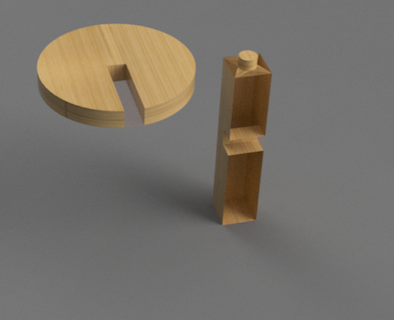
- Once I selected the layers (the shaft and the tiny cylinder above the shaft), I clicked the 'p' button on the keyboard. It projects the layout of the sketch with a maroon border and a new sketch is created. You can right click the new sketch created and click the save as dxf option.
- You can import the dxf file in the laser cutter software and then click the download, set the speed and power of the laser cutter according to the material. (speed = 30, power = 70 and material "cardboard". Thickness of the cardboard = 5mm. Notch of Disc = 50mm, Width of shaft = 51mm)
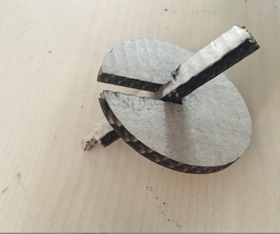
- This is how my final laser cut file looked like.
Download files for Fusion 360:
Fusion.stl
I referred the sheet attached below, for cutting materials on our SIL Laser machine.
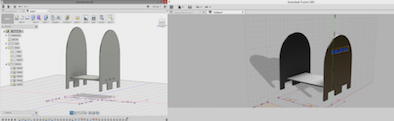
Group Assignment - Idol stand
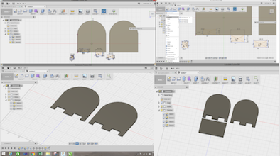
- We created a design using Autodesk Fusion 360.
- We created a rectangle of size (l = 112mm, b = 70mm) using the sketch tool. Also, we create a circle of radius 56mm
- We clicked the modify button and then selected the combine tool to combine the two shapes.
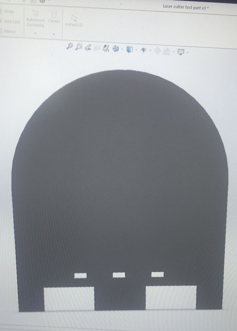
- To create a notch in the above plate, we created a notch of length 40mm x height 20mm and the distance between the notch and the edge of the plate is 5mm. Also, the distance between the two notch is 40mm.
- We create a copy of the same file i.e replicated the same design to create the second plate.
- We create another rectangle of length 112m x breadth 70mm as shown in the figure.
- We create three notches (l = 7mm, b = 3mm) on each side of the rectangle and the created 2D, dxf files from the 3D file we sketched.
- The 3 notches are separated by a distance of 15mm.
The final part assembled. We were out of black acrylic, so we used a red acrylic and press fitted the parts together.
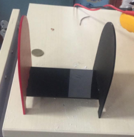
The design files are attached below:
lasercut.DXF
lasercut.igs
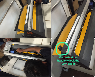
The next task is to use the Vinyl cutter
- We did this assignment at the Tata Center IIT Bombay.
- I used a Roland GX 24, CAMM-1 SERVO
- There are two sensors which, sense the vinyl sheet and a shaft comprising of a needle.
- Collect all the required material such as:
- Cutter, AC Adapter, Separating Knife, Roller Base, Twister, Material, Lan Cable And Laptop.
- Load the material from the back side of the machine by using roller base and pull out from the Grit rollers till the guide lines and load the material by using loading leaver.
- Press the force button and select the cutting force to 100gf
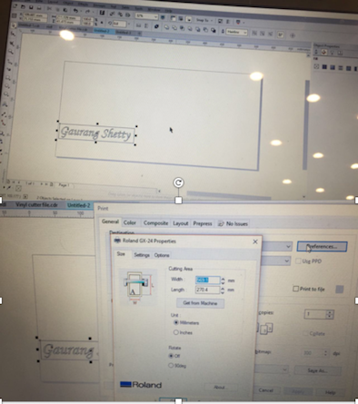
- I used corel draw software to write my name. "Gaurang Shetty"
- CLick object and then select convert to curves, to get the outlines of the name.
- In the object properties, in outlines, select black colour.
- Click fill in the 'object properties' and move the pointer to white colour, you will be able to see the outlines clearly.
Once the Corel draw file is ready and you click print we can click preferences and get the cutting area from the machine.
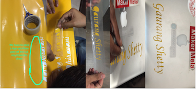
- Make a Rectangle around the text so it can easily peel off
- You can use a tape to peel it off easily from the vinyl sheet.
- Then Select the entire sketch using your mouse and then select the "hairline" option from the outline tool.
- You can see the sticker below.
Download files for Group Assignment:
Vinyl Cutter.cdr
Download files for Vinyl cutter:
Vinyl Cutter.cdr