Assignment 15
2.5.17Networking and Communications
Get started
I started working on the networking part of the project. I started searching more on networking.
I was very well versed with computer network or data network in a telecommunications network which allows nodes to share resources. In computer networks, networked computing devices exchange data with each other using a data link. The connections between nodes are established using either cable media or wireless media. Devices used for networking: Modem, Network Router, Bridge, Repeater, etc
In simple words, it is like the sequential conversation between two humans, where one asks and the other responds.
Task 1
The idea is to make two boards communicate. I tried to communicate between the two boards, which I've made in previous assignments and I will use the same board for my final project. The board shown below will be used to achieve the goal.
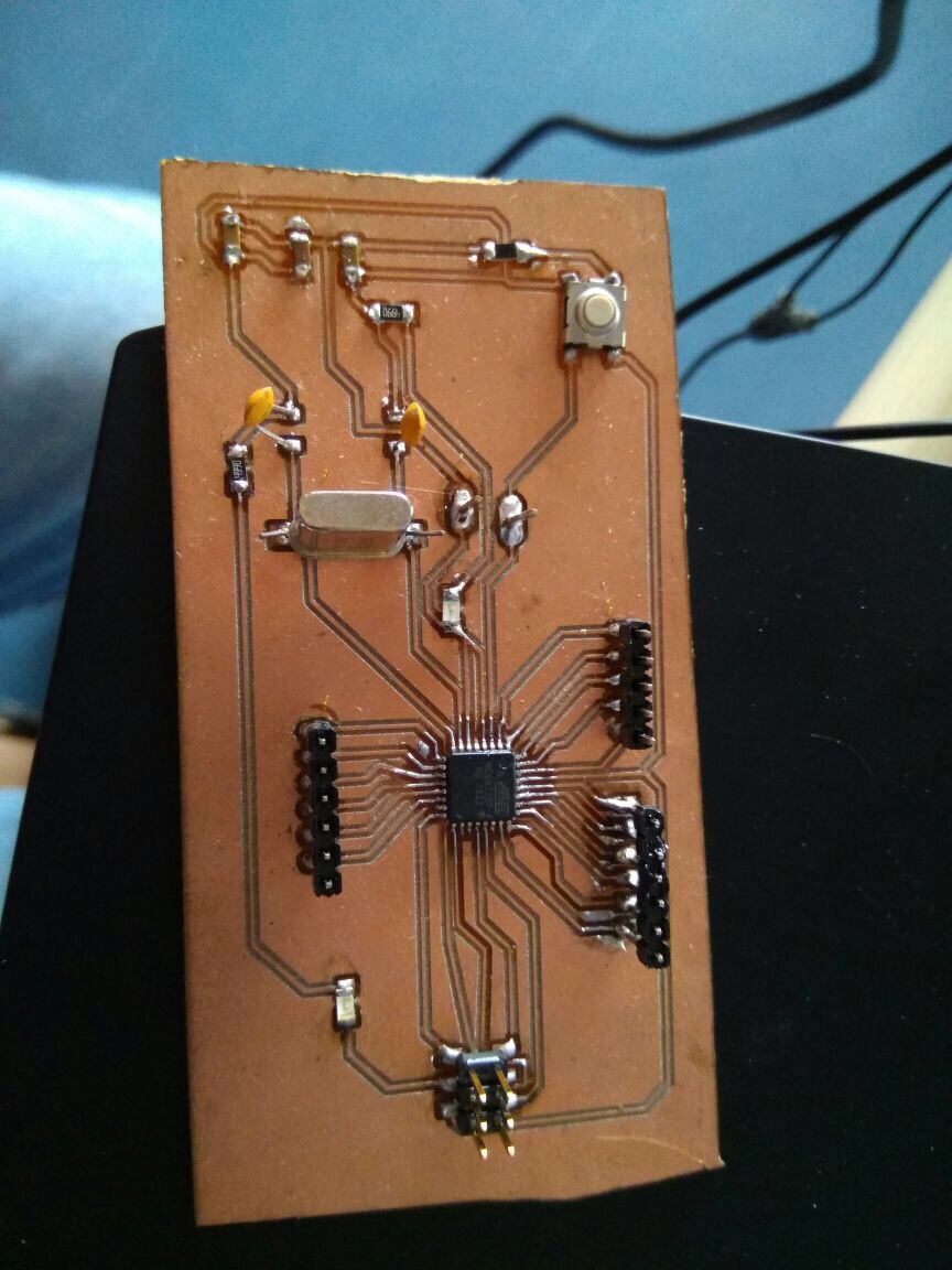
Final Board designs:
Downloadable file: finalboard.brd
Downloadable file: finalboard.sch
Touch sensor ATmega 328P Board 1 -> Taking input from a touch sensor Pin 2 and sending that data via serial communication to the other board pin 3
Downloadable file: Arduino code for board 1
Code:
#include < SPI.h>
#include < nRF24L01.h>
#include < RF24.h>
RF24 radio(7, 9); // CNS, CE
const byte address[6] = "00001";
char text ="true";
const int buttonPin = 2;
int buttonState = 0;
//initialising:
void setup()
{
pinMode(buttonPin, INPUT);
Serial.begin(115200);
// baud rate set to 115200 for communication serially:
radio.begin();
radio.openWritingPipe(address);
radio.setPALevel(RF24_PA_MIN);
radio.stopListening();
}
void loop() {
buttonState = digitalRead(buttonPin);
if (buttonState == HIGH)
{
text="true";
radio.write(&text, sizeof(text));
Serial.println(text);
delay(100);
}
if (buttonState == LOW)
{
text="false";
radio.write(&text, sizeof(text));
Serial.println(text);
delay(100);
}
}
Atmega 328 P Board 2 - Glowing LED on Pin 3
Downloadable file: Arduino code for board 2
Code:
#include < SPI.h>
#include < nRF24L01.h>
#include < RF24.h>
RF24 radio(7, 4);
const byte rxAddr[6] = "00001";
void setup()
{
// initialize digital pin 13 as an output.
pinMode(13, OUTPUT);
while (!Serial);
Serial.begin(9600);
radio.begin();
radio.openReadingPipe(0, rxAddr);
radio.startListening();
}
void loop()
{
if (radio.available())
{
char text[32] = {0};
radio.read(&text, sizeof(text));
if(text=="true")
{
digitalWrite(13, HIGH); // turn the LED on (HIGH is the voltage level)
delay(1000);
}
if(text=="false")
{
digitalWrite(13, LOW); // turn the LED on (HIGH is the voltage level)
delay(1000);
}
}
Protocol used
RS-232 Serial protocol
Baud Rate: 4800
Parity : None
Data size : 8-bit
About nRF24L01
The nRF24L01 is a highly integrated, ultra low power (ULP) 2Mbps RF transceiver IC for the 2.4GHz band. The power consumption of this module is just around 12mA during transmission, which is even lower than a single LED. The operating voltage of the module is from 1.9 to 3.6V, but the good thing is that the other pins tolerate 5V logic, so we can connect it to my board without using any logic level converters.
Range
The Range is dependent on the situation and is much more with clear line of sight outdoors than indoors with effects of walls and materials. The usual distance quoted by different suppliers for the low-power version module with the single chip is 200 Feet or 100 Meters, which is for open space and units operating at a Data Rate of 250KHz.
Making the connections
Board 1 - nRF24L01
Pin 9 - CE
Pin 10 - CS(N)
Pin 11 - MOSI
Pin 12 - MISO
Pin 13 - SCK
3.3v - VCC
GND - GND
On the Tranmitter Pin 13 - LED
Board 2 - nRF24L01
Pin 9 - CE
Pin 10 - CS(N)
Pin 11 - MOSI
Pin 12 - MISO
Pin 13 - SCK
3.3v - VCC
GND - GND
On the Receiver Pin 13 - LED
I connected the serial bus of both the boards. The idea was to send data from the touch sensor board.
I wanted to program both boards individually.
I took the programmer and run the code on the board. The sensor was connect on pin 3 and a touch on the sensor, would send data on the serial pin.
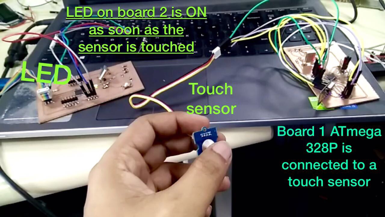
I programmed the second board to receive data from the serial pins and turn on the LED on pin 3.
The boards are working fine and data is being sent from the touch sensor to drive the led on the second board.