Assignment 13
2.5.17Input Devices
Objective of this weeks Assignment
Input Devices
What are Input Devices?
A hardware which is used to provide control signals to microcontroller in order to perform a tasks. The data will be logged in system, using this data we can perform tasks which is linked to that data set.
The following components may be used as Input Devices:
- 1.) Switch
- 2.) Potentiometer
- 3.) Light Dependent Resistor (LDR)
- 4.) Photodiode
- 5.) Opto-isolator
- 6.) Proximity switch
- 7.) Thermistor
- 8.) key pad
- 9.) Hall Effect Sensor
- 10.) Phototransistor
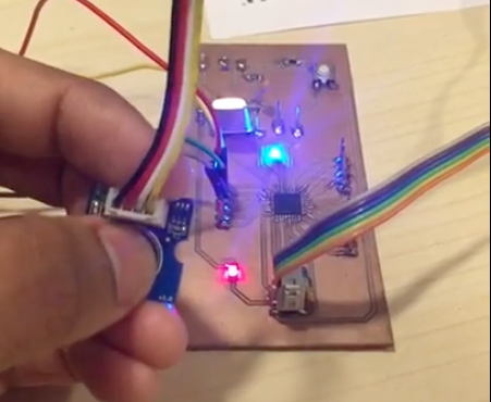
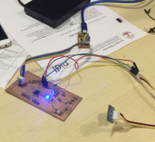
I have used an ATmega328P with a sound sensor and a touch sensor connected on pin a2 and an led on pin a3, which will turn on the led.
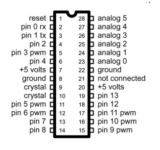
To be familiar with ATmega 328P one must read the datasheet thoroughly. Since, there will be a lot of information in the data sheet, its better to refer to the pinout of the ATmega.
- I loaded the Arduino bootloader into into the Atmega328P.
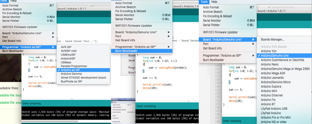
- I used an Arduino Uno to load the Arduino ISP.
- Later, I configured the Arduino IDE to use the Arduino Uno as an ISP Programmer. (Click: Tools>Programmer>Arduino as ISP)
- Now it’s time to talk about our Atmega328P, I loaded the bootloader on it. (Click: Tools > Burn Bootloader)
- The ATmega will be ready to program.
Troubleshooting
- Make a backup copy of the file: avrdude.conf
- Open the file avrdude.conf in a text editor
- Search for: “0x1e 0x95 0x0F” (this is the ATmega328P signature)
- Replace it with: “0x1e 0x95 0x14” (this is the ATmega328 signature)
- Save the file
- Restart the Arduino IDE
- Continue with the rest of the steps as mentioned above, and once bootloading is complete restore the backup copy you made.
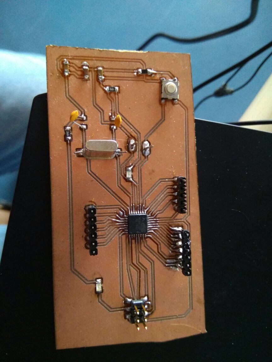
For this assignment I did the booting process on my previous board from assignment 10. I decided to use the same board, which I developed.
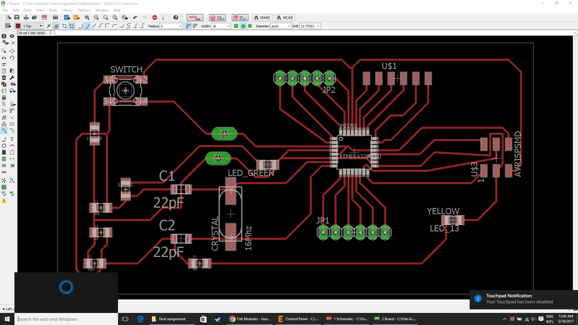
The board shown below will be used to achieve the goal.
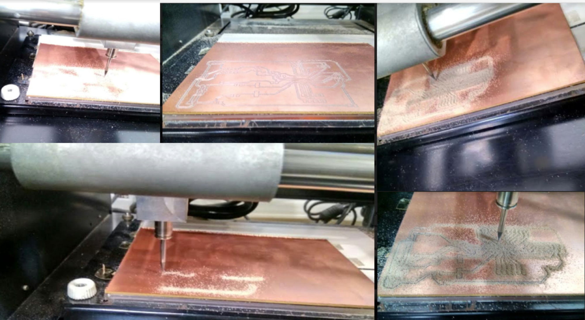
I started milling the board and soldering all the components on my board.
Components needed for the board:
| ATmega328P microcontroller | Capacitor C1,C2 22pF |
| C3 100uF | R1 10k ohm |
| C5 100nF | R2, R3 499ohm |
| LED 1 | LED 2 |
| 1 USB connector | AVRISP SMD |
| 1 Cystal 16MHz | 1 Switch |
| Jumpers J1 | Jumpers J2 |
| Three 6 pin connectors | one ribbon cable |
| Two single header pins | SMD Jumper J3 |
Final Board designs:
Downloadable file: finalboard.brd
Downloadable file: finalboard.sch
Steps involved are :
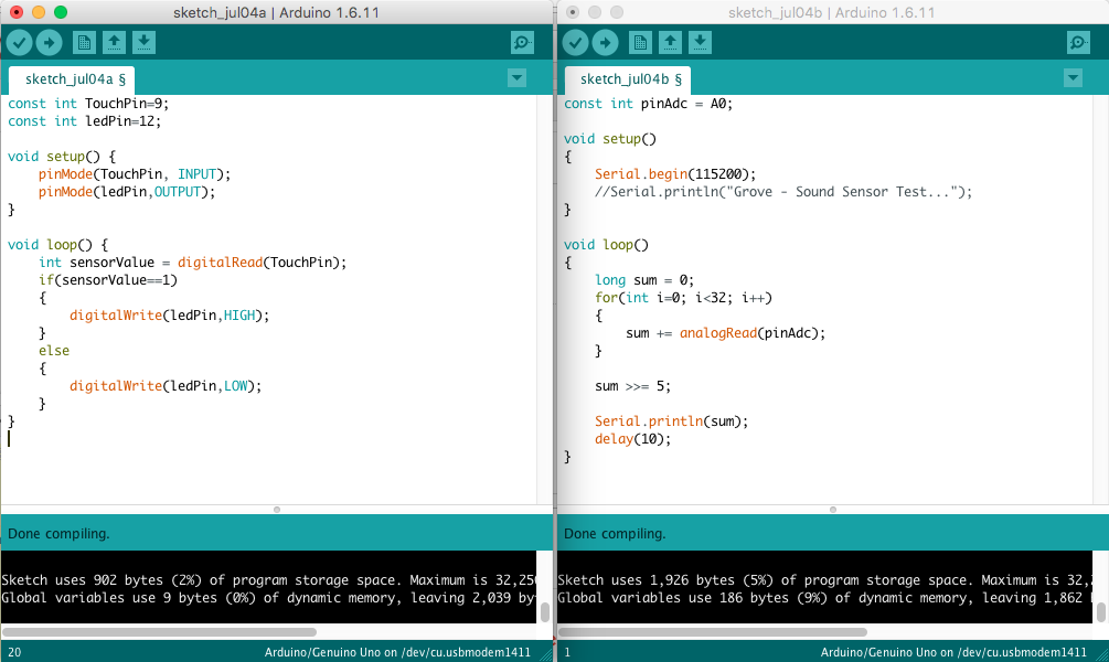
Programming the board through Arduino IDE
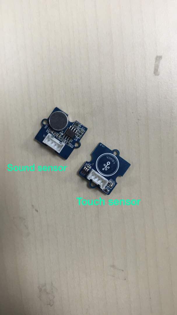
- Touch Sensor
Grove - Touch Sensor enables you to replace press with touch. It can detect the change in capacitance when a finger is near by. That means no matter your finger directly touches the pad or just stays close to the pad, Grove - Touch Sensor would show a HIGH output.
Specifications:
Operating Voltage: 2.0 - 5.5V
Operating Current(Vcc=3V):1.5 - 3.0μA
Operating Current(VDD=3V):3.5 - 7.0μA
Output Response Time: 60 - 220mS
Used Chipset: TTP223-BA6
- Sound sensor
Grove - Sound Sensor can detect the sound strength of the environment. The main component of the module is a simple microphone, which is based on the LM358 amplifier and an electret microphone. This module's output is analog and can be easily sampled and tested by a Seeeduino
Specifications:
Operating voltage range: 4-12V
Operating current (Vcc=5V): 4-8mA
Voltage Gain (VS=6V, f=1 kHz): 26dB
Microphone sensitivity (1Khz): 52-48dB
Microphone Impedance: 2.2KΩ
Microphone Frequency: 16-20Khz
Microphone S/N ratio: 54dB
Touch ___________________________________________ Sound___________________________________________
Video for touch
Video for Sound
Downloadable files:
Downloadable file: touch.ino
Downloadable file: sound.ino