Assignment 10
29.3.17Output Device
Objective of this weeks Assignment
I have thought and researched; what could I use as an output device for my final project?, a fan?, a pump? an LCD display?
I thought an LCD module would be a superb Output device! It would enable me to create visual data. I consulted my instructor Yogesh and he too was cool with the output device I selected.
In this week I wanted to write more about details, so I decided to share a bit about the software Eagle and basics of how Eagle works.
Eagle's UI is designed with what is called a modal interface. That is, you select one mode, perform it a bunch of times, as opposed to selecting an object and applying an single operation at a time. When used properly, this allows you to work very rapidly, but it can also be a major source of aggravation if you are used to the Windows-y way of doing things.
Steps for creating our own Satshakit is as follows:
I used Eagle Software for designing of my PCB for my final project. I will be going to use the same for my rest of
the assignments.
.png "PNG FILE")
Under the command button : ADD command to add the components to the design layout which is available.
.png "PNG FILE")
I add the atmega328p which is the UNO chip. I will be using the same chip for my final project.
.png "PNG FILE")
I added all the components such as capacitor, Leds, button , AVRISP SMD header pins, resistor,
etc.
.png "PNG FILE")
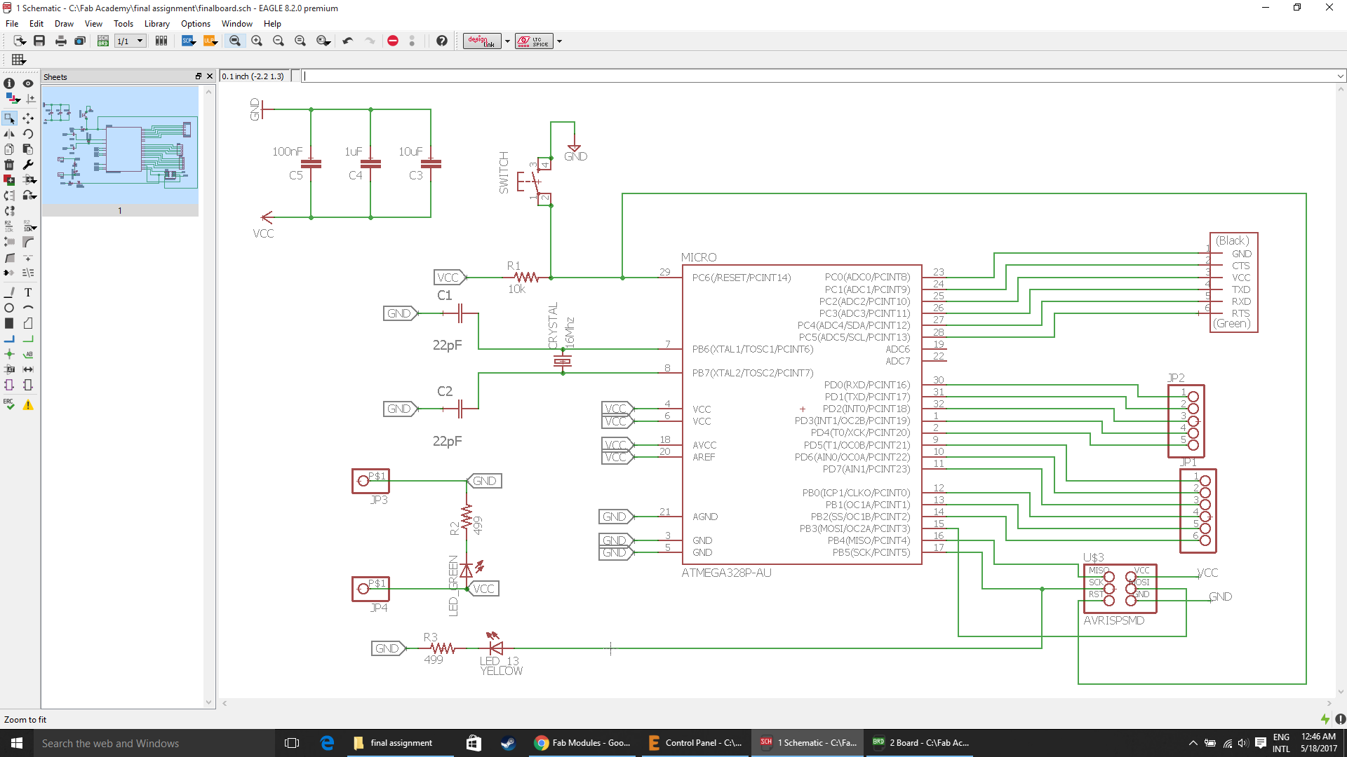
I used the command net to join the two components pins with each other.
.png "PNG FILE")
After connecting all the component with each other, to know wether all the components are connected or not with the
ERC command.
.png "PNG FILE")
DRC parameters
.png "PNG FILE")
.png "PNG FILE")
.png "PNG FILE")
After arranging the components, I routed the wire with the routing option available from the command button bar. Before using the route option, select the ratsnet to so that the number of wires should be reduced. Then use the route option to make respective connections.
.png "PNG FILE")
Then export the file for fabrication. Save it in .png format 600dpi monochrome.
.png "PNG FILE")
Eagle has four basic views: Library, Schematic, Board, and Control Panel.
- Control Panel is the main window, it launches everything else and when you close it, all subordinate windows get closed.
- Library - Allows you to manage and edit parts. Advanced usage of this will not be covered in this tutorial
- Schematic - This is where you draw the schematic for your project. It defines the parts you have in your project, and which pins on the parts should be connected.
- Board - This is where you lay out the pieces of your project and physically connect the correct pins as defined in the Schematic.
Note that the Schematic's job is only to define the parts and the connections between them. Only in Board layout does it matter where the parts physically go. On Schematics, parts are laid out where they make sense electrically, on Boards, they are laid out where they physically make sense, thus a resistor that is right next to a part in the Schematic may end up as far away from that part as possible in the Board.
The control panel is the main window of Eagle. When you close it, all windows that it opened get closed as well. A description of the various categories in the Control Panel:
- -- Libraries (.lbr files) store the individual parts that you add to your board.
- -- Design Rules (.dru) are what the design rule checker (aka the idiot-checker) uses.
- -- User Language Programs (.ulp) use Eagle's User Language (pretty much an advanced scripting language) to do stuff that would normally be difficult, tedious, or impossible without them.
- -- Scripts (.scr) are essentially just groups of eagle commands commands. Simpler and less powerful than ulps.
- -- CAM Jobs (.cam) export to other formats
- -- Projects (.sch, .pcb, etc) are where your circuit boards, schematics, and whatever else live
So to start things off, right-click on the 'eagle', select 'New Project'.
The schematic window is where you create and edit the schematic. Once your schematic is ready you are good to go.
In short you need to do all these steps:
- Create a New Project and Schematic
- Add the Parts to the Schematic
- Connect the Parts
- Label and Name All of the Nets
- Give the Parts Some Values
- Electrical Rule Check
- Route the Parts
- Do the Design Rule Check
- Once you've finished routing and have no more DRC errors, you're done
Now click File>Switch to Board to switch to the board layout side of things. If you didn't have a .pcb file paired with this file, it will automatically create one and drop all of the parts outside of the PCB area.
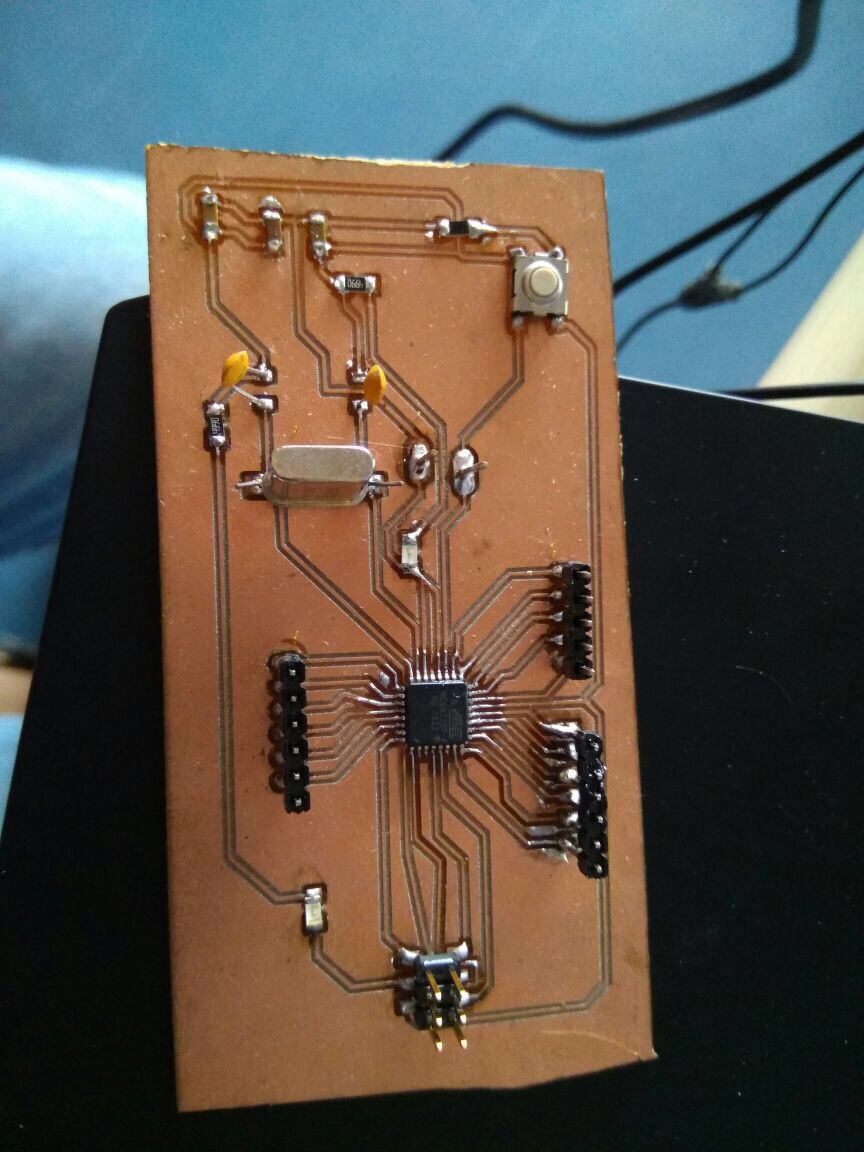
The board shown below will be used to achieve the goal.
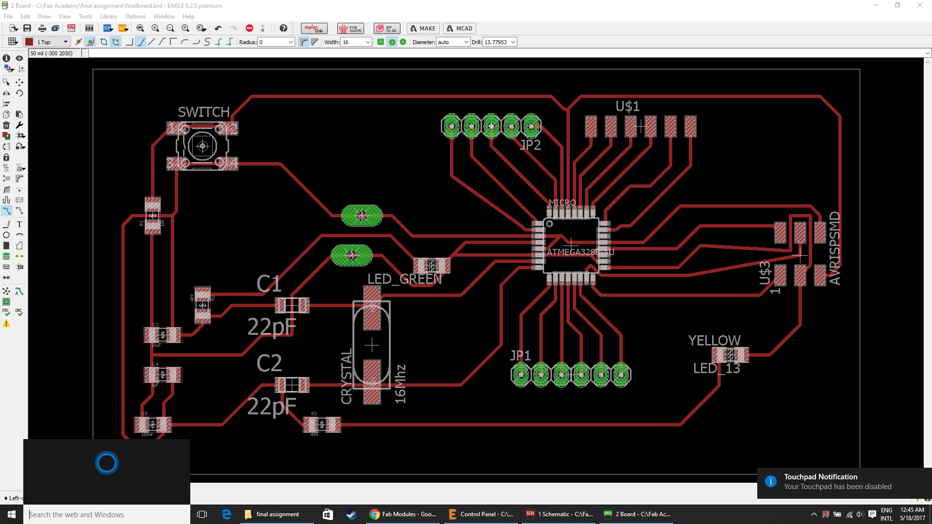
.png "PNG FILE")
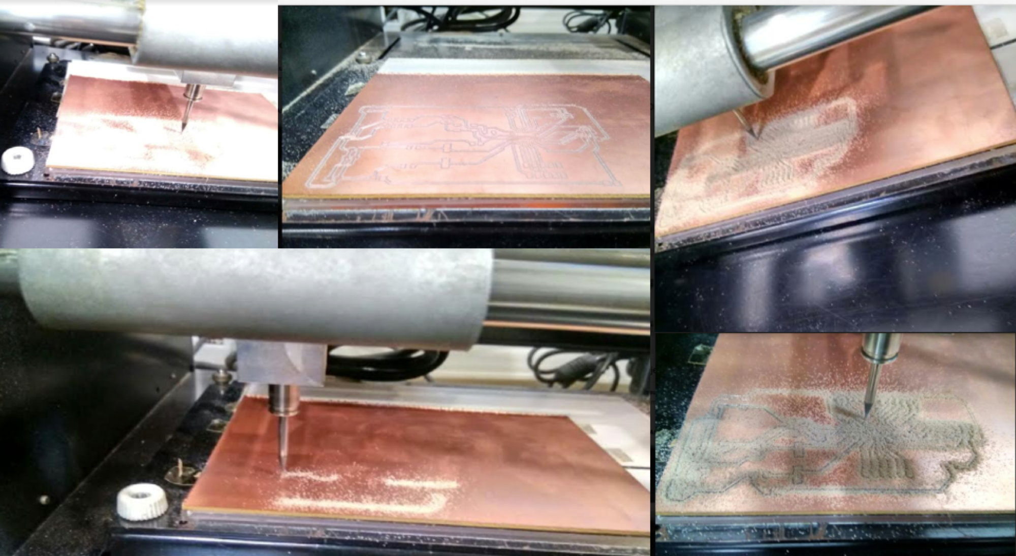
I started milling the board and soldering all the components on my board.
- Bit Adjustments:
1. Insert a 1/32 cutting tool in a collet.
Do not insert to the portion of an edge. When you use included cutting tool,
refer to the following figure.
2. Tighten the set screw with hexagonal wrench.
3. Click [View] of VPanel.
A spindle head moves to a center and a table moves to the front.
4. Loosely tighten the collet with cutting tool.
Insert the collet, and then loosely tighten.
5. Fully tighten the collet.
Tightly secure the collet by using two spanners.
Components needed for the board:
| ATmega328P microcontroller | Capacitor C1,C2 22pF |
| C3 100uF | R1 10k ohm |
| C5 100nF | R2, R3 499ohm |
| LED 1 | LED 2 |
| 1 USB connector | AVRISP SMD |
| 1 Cystal 16MHz | 1 Switch |
| Jumpers J1 | Jumpers J2 |
| Three 6 pin connectors | one ribbon cable |
| Two single header pins | SMD Jumper J3 |
Tips for SMD Soldering
Place the IC carefully making sure the pins are lined up as well as they can be, on some of the larger pin count packages this can be a bit difficult. In some ways this can be the hardest step.
Once properly lined up tack a few pins or use a high temp adhesive like a paper tape to hold the IC in place. Were now ready to solder it!
Start by tinning our tip, clean it and fill the bevel with a bit of solder. This "pocket" of solder will glide over the pins heating them and depositing the perfect amount of solder on each one. Because of the flux, surface tension and temperature differences the solder makes very high quality fillets that usually require no solder wick as the right amount is deposited at each transition.
The key here is to make sure the is enough solder on the bevel to make good connection, but not too much to over load the "pocket". Drag time should be kept minimal but there should be enough time for a wetting action to occur. A good initial time is about 1 second per pin but this depends on a number of factors, and can be sped up. But it is a good place to start at first.
Final Board designs:
Downloadable file: finalboard.brd
Downloadable file: finalboard.sch
My Goal
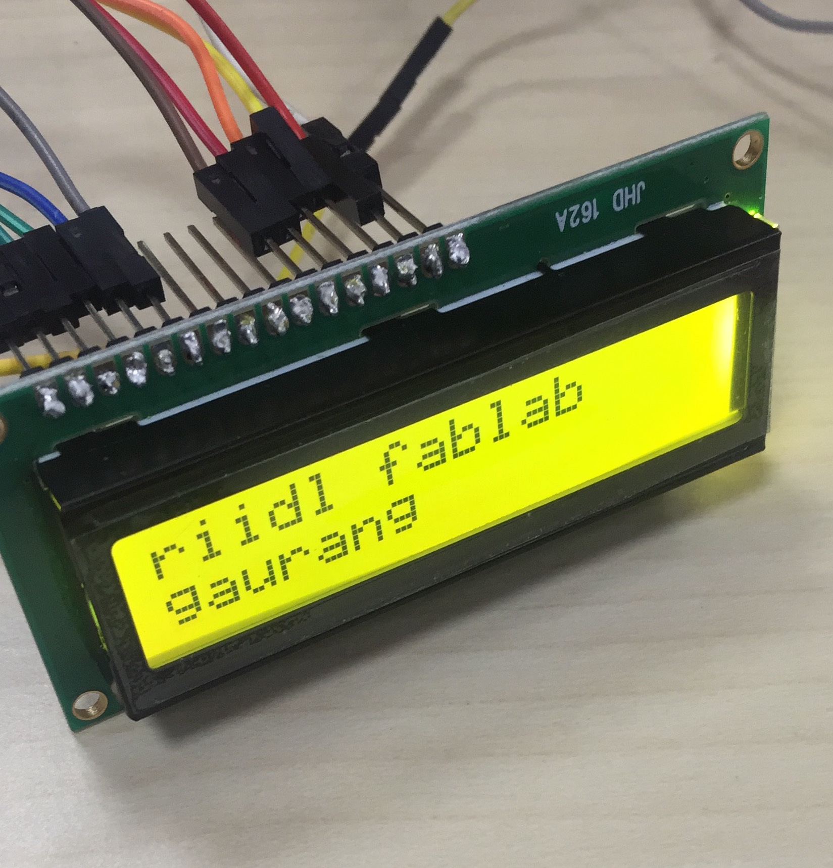
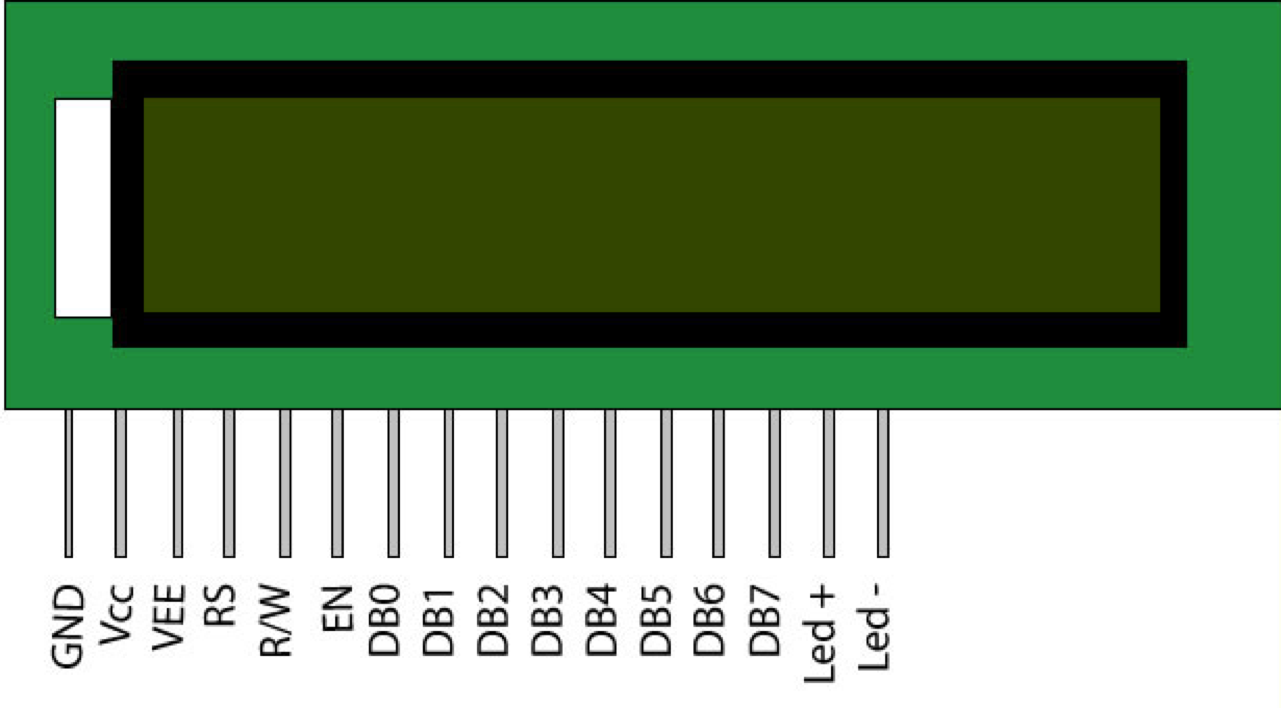
Add an output device to a microcontroller board I've designed and program it to do something. 16x2 LCD
The LCD display comes with no connector by default. This way you can solder wires to it, solder a connector on it, whatever you want. I choose to solder the connectors to the back so I could press the LCD display on the breadboard. To do this, snap of a row of connectors (16 pieces) and stick them (short pin up) trough the LCD display connectors.
The pin diagram of LCD 16x2 is shown below: Reference Link
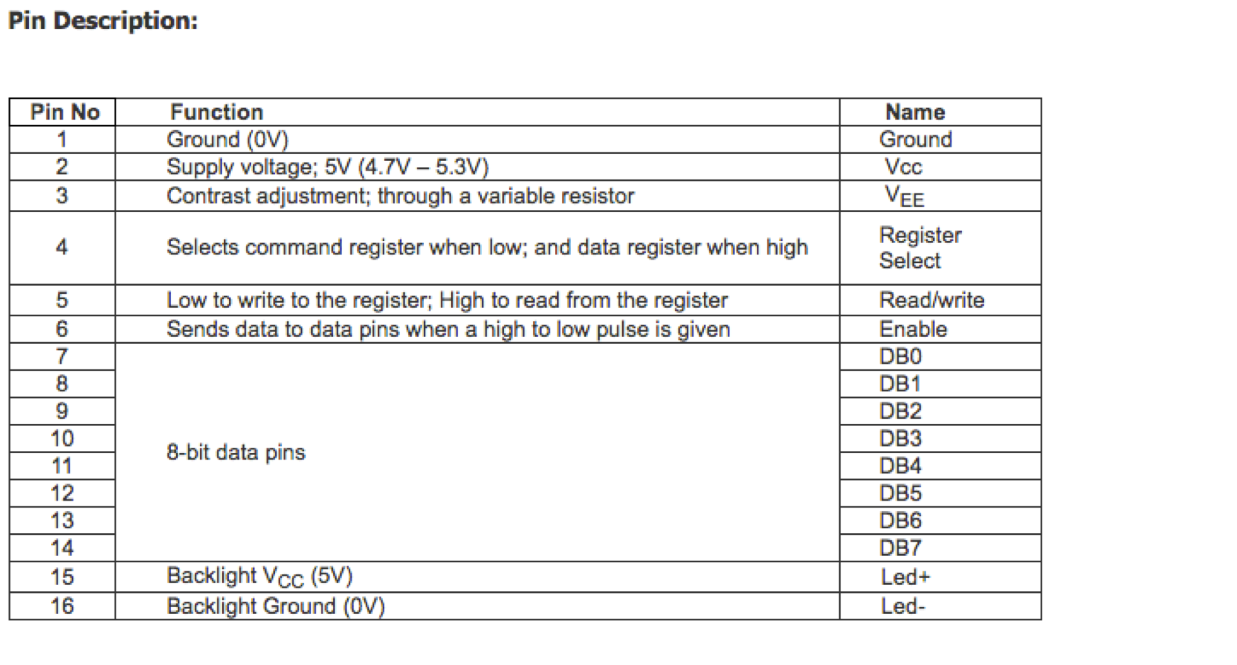
I studied the data sheets as mentioned by Prof. Neil.
I used this link as a reference to design my board
Components Used
AtTiny44a
Capacitor 1uF
Resistor - 1K, 10K and 100K
2x5 Header LCD
2x3 ISP header
Resonator XTAL1 20MHz
CONNECTING THE DISPLAY
The circuit connection between LCD and my board:
* LCD RS pin 4 to digital pin 12
* LCD Enable pin 6 to digital pin 11
* LCD D4 pin 11 to digital pin 5
* LCD D5 pin 12 to digital pin 4
* LCD D6 pin 13 to digital pin 3
* LCD D7 pin 14 to digital pin 2
* LCD R/W pin 5 to ground
* LCD VSS pin 16 to ground
* LCD VCC pin 15 to 5V
* LCD Pin 3 to ground (so that the display is glowing bright)
* ends to +5V and ground
Soldering the LCD display
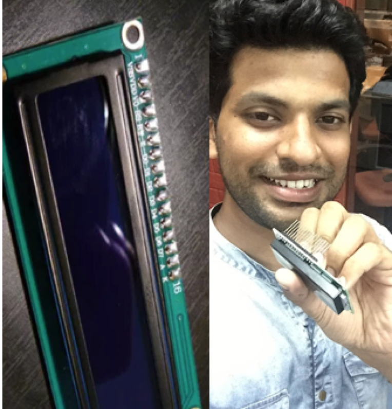
My soldering was done nicely! I was excited to see the clean soldering. I immediately started connecting the board to the LCD and started to write the code. First you need to power the display and its backlight. So, I tried connecting the LCD to the board I made.
THE CODE
To check my code I used the program below!
I used the Arduino IDE to run my code!
This code prints "riidl fablab" to the LCD and shows the time.
The Code!
Downloadable file of the Arduino IDE code.
#include
// initialize the library with the numbers of the interface pins
LiquidCrystal lcd(12, 11, 5, 4, 3, 2);
// this is the first step when you plan to use an lcd
void setup() {
// set up the LCD's number of columns and rows:
lcd.begin(16, 2);
// Print a message to the LCD.
lcd.print("riidl fablab - 377 - Gaurang!");
delay(1000);
}
void loop() {
// scroll 13 positions to the left. This is the string length
// to move it offscreen left:
for (int positionCounter = 0; positionCounter < 13; positionCounter++) {
// scroll one position left:
lcd.scrollDisplayLeft();
//delaying for a moment
delay(350);
}
// scroll 29 positions (string length + display length) to the right
// to move it offscreen right:
for (int positionCounter = 0; positionCounter < 29; positionCounter++) {
// scroll one position right:
lcd.scrollDisplayRight();
//delaying for a moment:
delay(350);
}
// scroll 16 positions (display length + string length) to the left
// to move it back to center:
for (int positionCounter = 0; positionCounter < 16; positionCounter++) {
// scroll one position left:
lcd.scrollDisplayLeft();
//delaying for a moment:
delay(350);
}
// delay at the end of the full loop:
delay(1000);
}
I tried writing various things on the LCD module. I wrote riidl fablab and my name initially. Also, I recorded a video of the LCD module, where I used a scroll program.