WEEK 9 & 11

ASSIGNMENT
1. To design the mechanics to the machine that you plan to element in your group
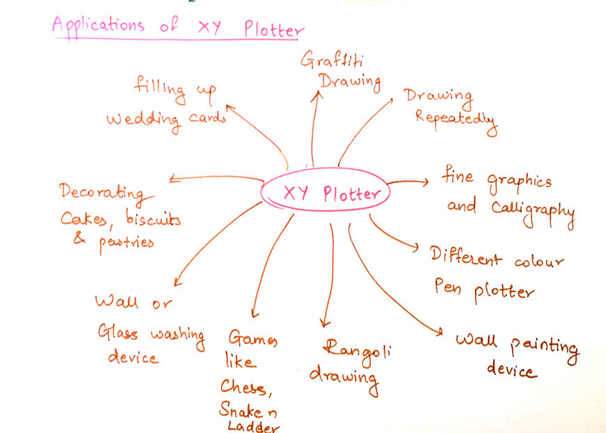
Initially all of us started to think upon what all we will be making for the machine. The ideas were collaborated together for the major decisioned or idea brainstorming and machine building. XY plotter is a Machine that will work with commonly available pens and sketching tools available at normal stationary stores. Our intention is that the machine will be capable of drawing any digi for starter and gradually be improvised to draw mandala type patterns in the following weeks.
Later we decided to start working as a system and the flow of work is as following:
Making a basic design and structure of machine
Figuring out the material and components needed
Making a 3D model
Making a working model of machine
Making it automated
Final testing and video making
THE MECHANISM
THE H-BOT CONCEPT
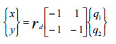
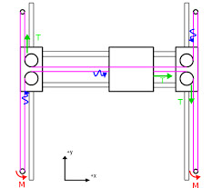
This H-Bot concept represents the interaction of two rotary drives which are connected by a single H-shaped circumferential timing belt around two staggered linear axes in a gantrytype like configuration, see figure 1. The kinematics of the H-Bot mechanism formulated in (1), where x and y are the TCP- and q1 and q2 are the drive-coordinates in radians and rd is the drive’s pulleys radius:
Due to the fact that the drives do not have to be moved the achievable dynamic values can be quite high. Another aspect of this
concept in contrast to delta-robot like kinematics is that the weight of the work load is carried by the linear guideways and not by the drives
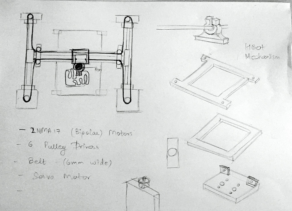
The following parts were listed by the team to start machine building
The Chassis design (MDF laser cut)
Precision stepper motors (NEMA 17 Bipolar Stepper Motors)
Servo Motor (FUTABA S003)
Linear Bearing
Belt
Rod

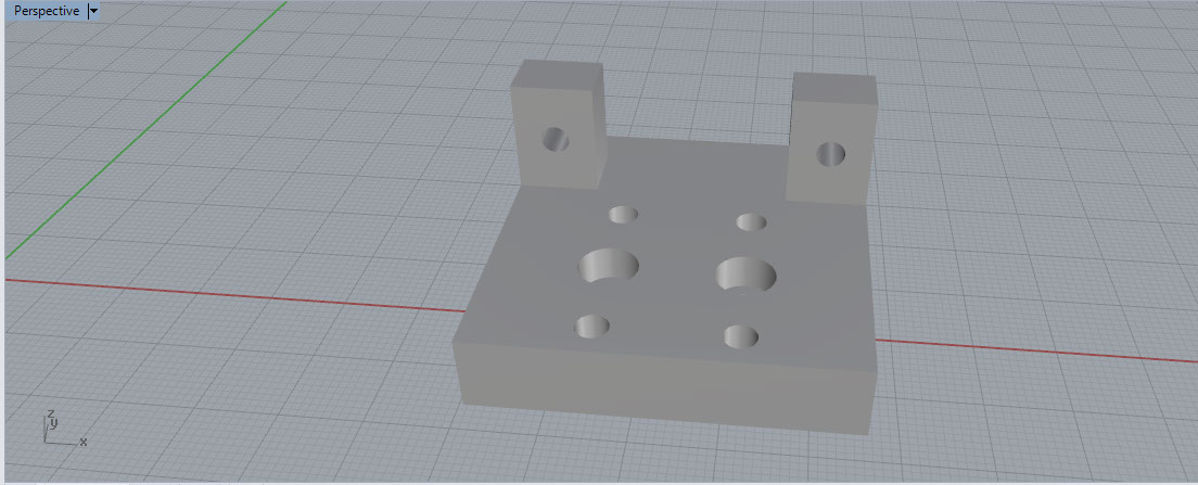
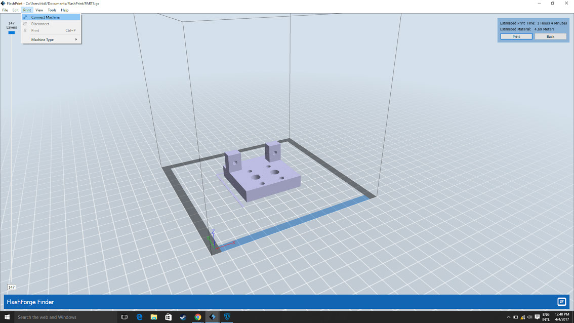
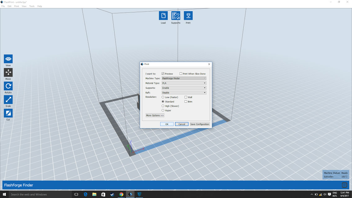
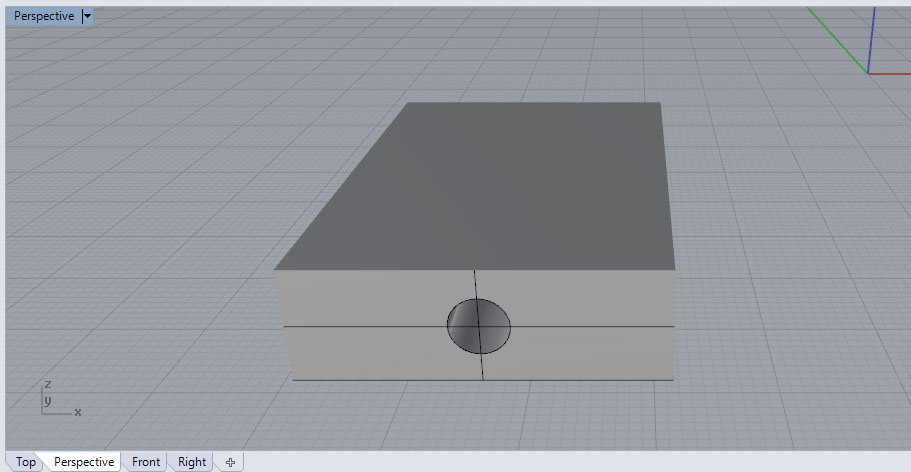
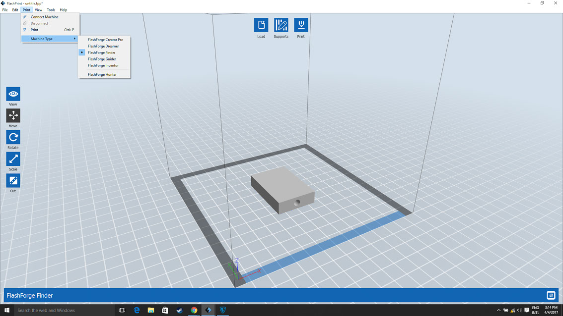
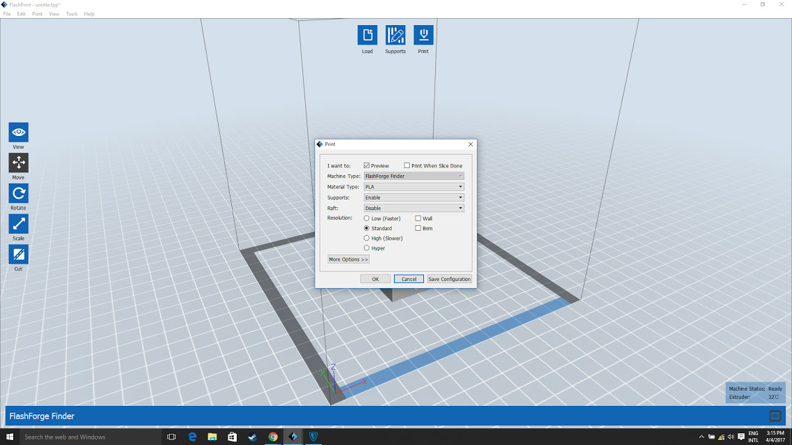
We decided to print some parts for creating the parts of the H Bot Mechanism for the bearings to be attached and pulley to be
placed I used Rhino 5 to create the design of the files and saved them as .stl. Used FlashPrint to slice the parts and generate
the required G code need for the print
Group Page Link:
http://archive.fabacademy.org/archives/2017/fablabriidl/students/377/assignment111.html
Site created by Lavina Utamani using Adobe Muse | fabacademy 2017