ASSIGNMENT
1. Read a micro controller data sheet
2. Program board to do something, with as many different programming languages and programming environments as possible.
Reading a Micro controller Data sheet
Datasheets are instruction manuals for electronic components. They (hopefully) explain exactly what a component does and how to use it. Unfortunately these documents are usually written by engineers for other engineers, and as such they can often be difficult to read, especially for newcomers. Nevertheless, datasheets are still the best place to find the details you need to design a circuit or get one working. In order to use a PIC microcontroller, a flip-flop, a photodetector, or practically any electronic device, you need to consult a datasheet. This is the document that the manufacturer provides telling you
• the typical device performance
• minimum and maximum requirements and characteristics
• what you can do to the device without harming it
• suggested uses and hints
Where do you find datasheets? Nowadays you can find almost any datasheet on the internet, often in PDF (Acrobat) form. For example, the LM555 datasheet from National Semiconductor is on their website at www.national.com.
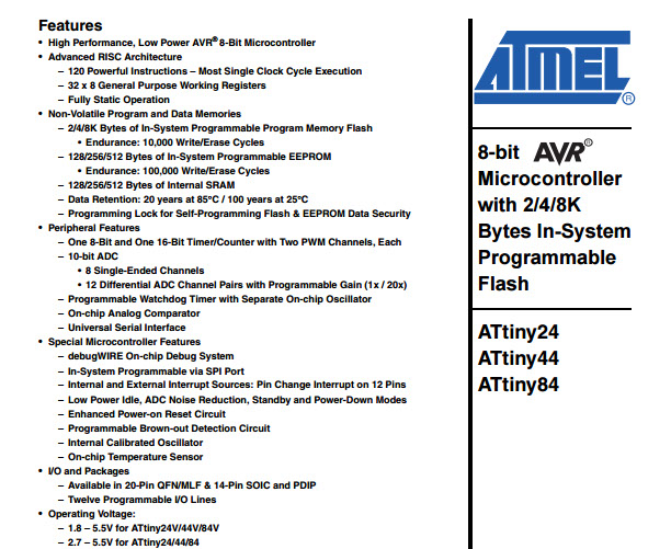
Data sheet of ATtiny44 : http://www.atmel.com/images/doc8006.pdf
Features tell us about the general characteristics always check the electrical characteristics for conditions and exceptions
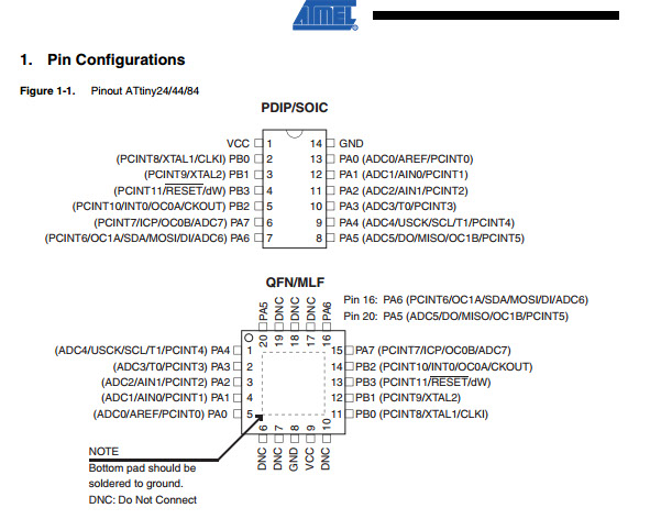
Pin configuration helps you decide where can put your inputs and output devices. Check out the packages and their specific pin out while planning
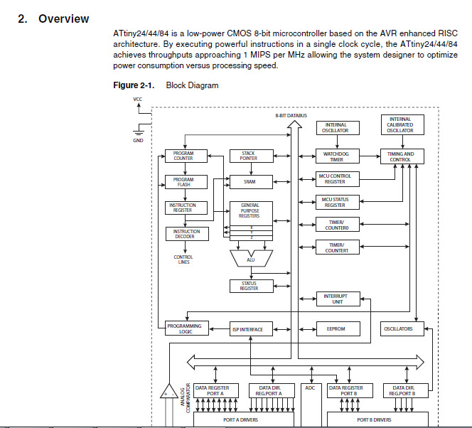
Functional block diagram that shows the internal functions of the part. This page will often give us a
good first impression as to whether potential part will work for the project or not
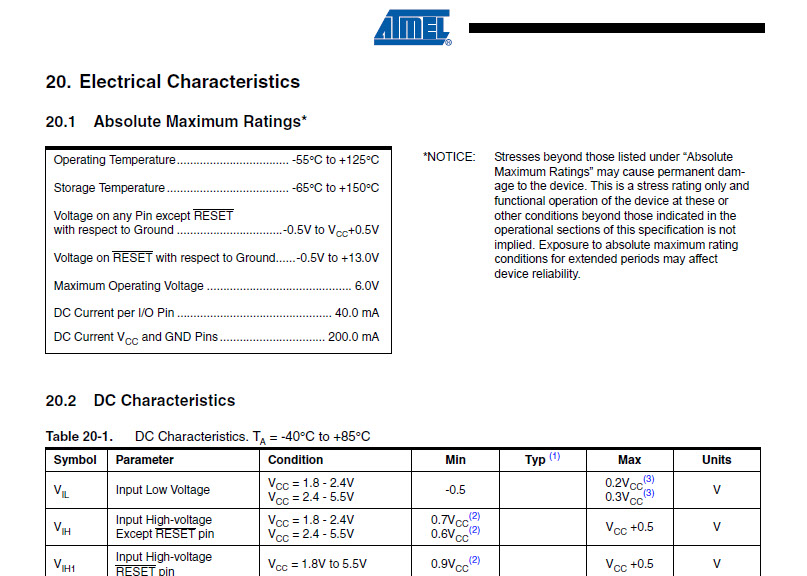
Electrical characteristics are the most important features to be considered in the sheet while designing the circuit
Absolute Maximum ratings for the ATtiny are given here.
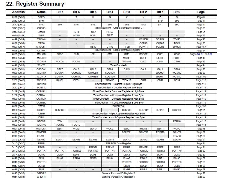
Resisters are the data holding spaces where micro-controller holds the specific data. These resistors can or can't be read or written with the content. Few resister holds the status of the device, some of them holds the configuration of the device.
Programming of the board
How to program an ATtiny45, ATtiny85, ATtiny44 or ATtiny84 microcontroller using the Arduino software.
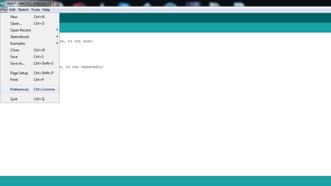
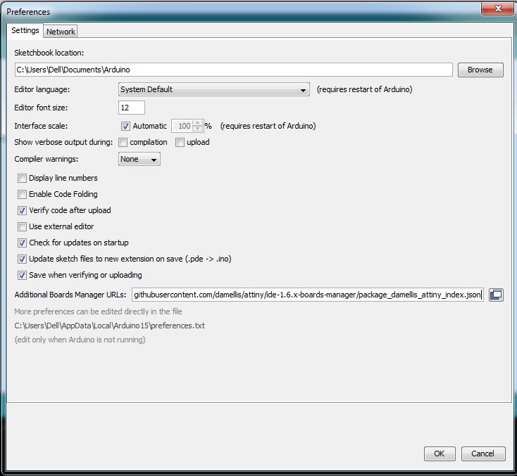
In the version of Arduino software I started using I realised is offering an easy way of customization such as installing additional board and the libraries. So, I open up Arduino Preferences settings located under the Edit menu and added the Additional board URL which is given on HiLow tech website.
https://raw.githubusercontent.com/damellis/attiny/ide-1.6.x-boards-manager/package_damellis_attiny_index.json
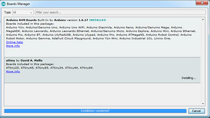
Once I did that then I restarted the Arduino IDE, and then again visited the Board Manager and searched for the Attiny version of the chip availability. I found it on search result then I clicked on Download to install them.
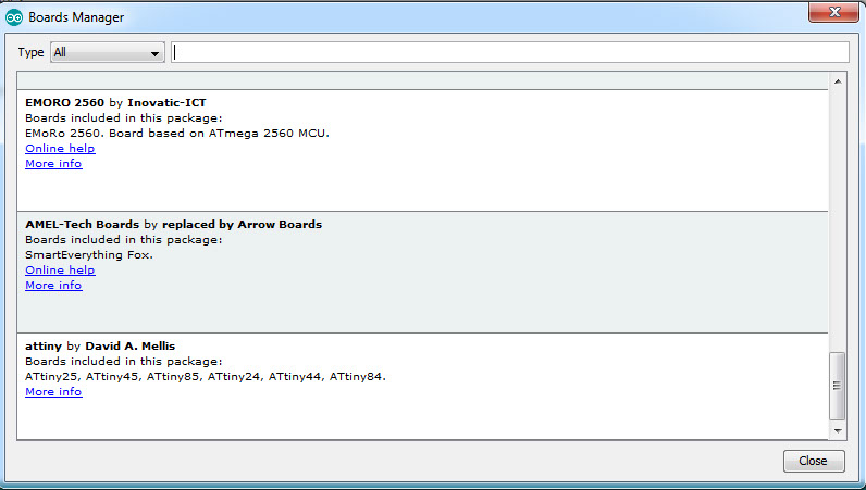
Into Tools to Board Manager
Check whether the attiny is seen and install the board from there
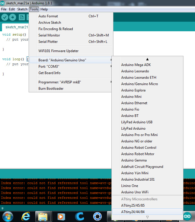
Into tools
Go to Boards
Find the attiny boards
and select the one with attiny44
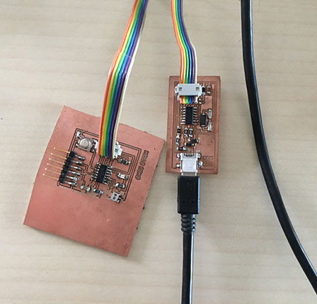
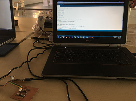
Connection rules: See the circuit diagram of the board and identify the pins that we have to connect with the arduino.
Colour code for the connection of six pins from the board
GND- ORANGE
MOSI - RED
V - WHITE
RST - YELLOW
SCK - GREEN
MISO - BLACK
Now this 6 pins are connected to the Arduino board.
PIN_MOSI to 11
PIN_MISO to 12
PIN_SCK to 13
PIN_RST to 10
GND to ground of arduino
V to 5V of arduino
Then I used the sample code from the arduino software
int LED_BUILTIN = 6 ;
// the setup function runs once when you press reset or power the board
void setup() {
// initialize digital pin LED_BUILTIN as an output.
pinMode(LED_BUILTIN, OUTPUT);
}
// the loop function runs over and over again forever
void loop() {
digitalWrite(LED_BUILTIN, HIGH); // turn the LED on (HIGH is the voltage level)
delay(1000); // wait for a second
digitalWrite(LED_BUILTIN, LOW); // turn the LED off by making the voltage LOW
delay(1000); // wait for a second
}
Site created by Lavina Utamani using Adobe Muse | fabacademy 2017
To further understand the reading of datasheets One may refer to the following tutorial https://www.sparkfun.com/tutorials/223
The LED didn't glow .On debugging the instructor found that the LED was connected in reverse direction after attaching a new LED correctly we could get the board working