
ASSIGNMENT
1. Scanning an Object
2. Design and 3D print object that could not be made subtractively
BACK
A 3D scanner is a device that analyses a real-world object or environment to collect data on its shape and possibly its appearance (e.g. colour). The collected data can then be used to construct digital three-dimensional models. The 3D scanning process can be used for reverse engineering by which the mesh of a real-world object is created. This meshed object can be modified using various software to create file compatible for 3d printing
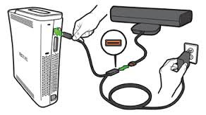
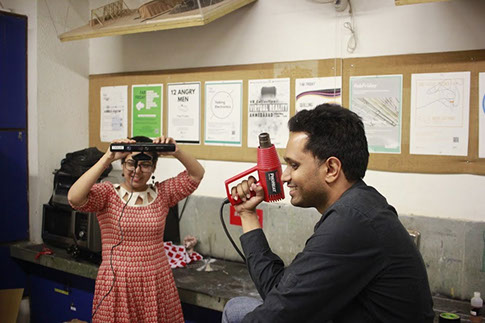
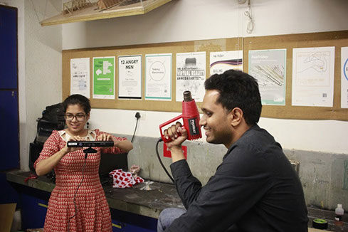
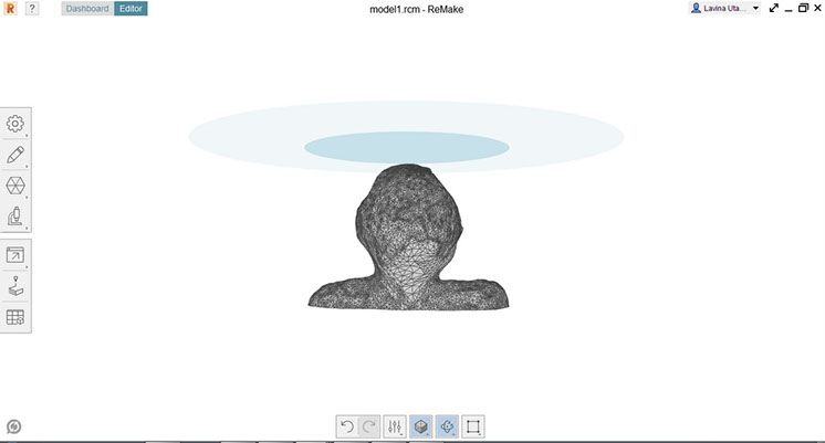
I used the Kinect Sensor to start with 3D scanning process. Before the scanning a basic brief about the kinect hardware was grasped
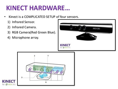
Scanning using Kinnect scanner: This excerise was fun as I group with Viraj Gandhi and we decided to scan human for printing this week. So using the scanner was a skilled task where one had to take continuous frames to reconnect a 3d image in the software as well as move around in 360 degree rotation
https://remake.autodesk.com/resources
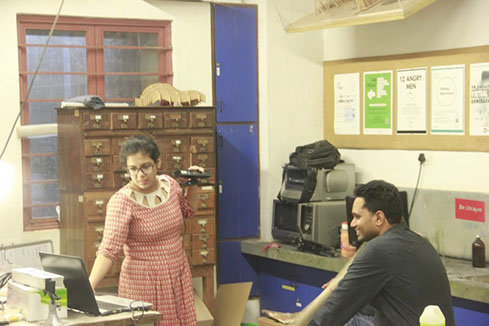
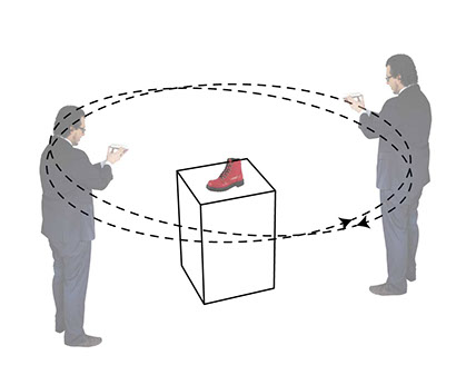
Out of the two ways of scanning was you manually rotate with the scanner around the object to scan the object of interest. The problems faced were in managing the cables will rotating around.
Sketchfab was the reconstruction software used to generate the mesh files, since the software limited the access to 5000 polygons for the trial version we could upload the files online https://sketchfab.com/models/c28428f960e04ad58da8557a042b7309 ,but failed to generate the stl or obj files for printing them.
If you don't have a 3D Scanner, you can use your mobile camera to capture Photos and convert to 3d objects this is called
PHOTOGRAMMETRY
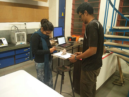
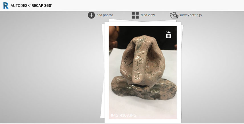
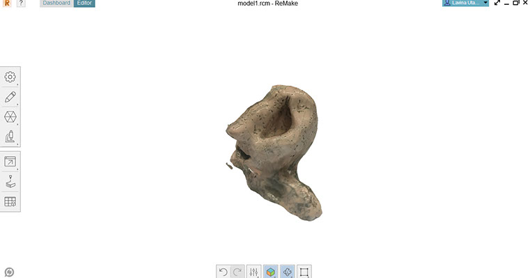
For this trial I picked up a Ceramic object and put it on the turntable so that I could rotate the object around keeping the camera stationary taking
System Requirements
You can check the full requirements at the bottom of this page but it’s good to note that if you’re a Windows user and want to use local processing, you’ll need a decent machine — especially a good graphics card. A Nvidia Geforce GFX gaming card is the minimum. Autodesk also says that 64Gb of RAM is required, although I experienced no problems with running ReMake with half of that.
Shooting the Photos
I won’t go into too much detail here, because all basic photogrammetry tips apply:
Shoot many photos in 360° circles at at least 2-3 different heights with 40% or more overlap.
Use a tripod when possible
Use the smallest aperture (the highest f-stop number) so everything is in focus.
Use the lowest ISO setting to prevent noise.
Lock as many settings as possible, especially exposure.
Don’t change the focal distance (don’t zoom) or – even better — use a prime lens.
Shoot outside when possible, but avoiding direct sunlight (overcast days are great).
Indoors you can use a diffuse studio light setup for better results.
Shoot in RAW + JPEG. Use the JPEGs when time is of the essence and convert RAW to JPEG for high-profile or problematic projects.
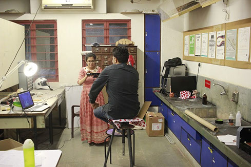
I used my mobile camera, set the object on the turntable and took continuous shots by rotating the table uniformly. 64 photos were
shot and processed in Remake and Recap
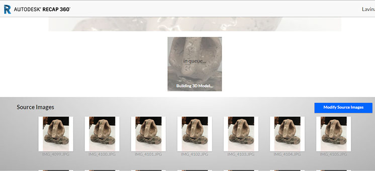
The Images were uploaded into different 3D reconstruction software for testing, Remake , Recap Autodesk & VisualSFM to compare the reconstruction techniques
USING REMAKE
ReMake is an end-to-end solution for converting reality captured with photos or scans into high-definition 3D meshes. These meshes that can be cleaned up, fixed, edited, scaled, measured, re-topologized, decimated, aligned, compared and optimized for downstream workflows entirely in ReMake. It handles reverse engineering as support for design and engineering, for asset creation for AR/VR, film, game, art, for archiving and preserving heritage, digital fabrication or publishing interactive experiences on the Web and mobile.
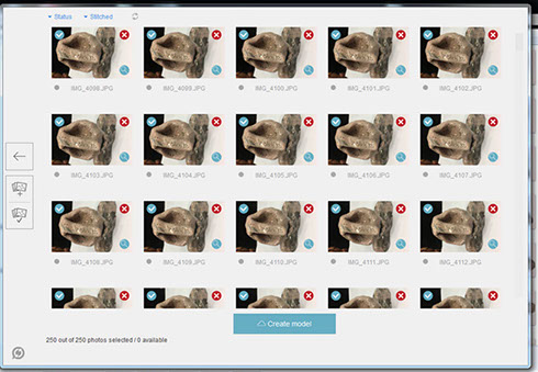
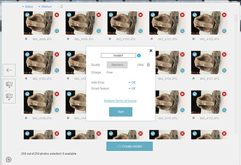
USING AUTODESK RECAP 360
From aerial drones flying GoPro cameras to digital SLRs to smartphones, use any camera to document your physical project. Photo on ReCap 360 can stitch photos and turn them into a 3D mesh or point cloud, creating a high-resolution, textured model that can be imported into other Autodesk software.
A key addition to the complete 2014 portfolio of Suites is Autodesk® ReCap™ product, a family of powerful and easy-to-use software and services on the desktop and in the cloud to create intelligent 3D data from captured photos and laser scans in a streamlined workflow

After the reconstruction software generates a 3d object. The object created here might have some holes or lost part or detail. If the hole is insignificant you can simply patch the hole in the object. Cut and create a flat base for a good finished print of the object.
The object is exported or downloaded as .stl
Options int the toolbar on left side allow you to render the object in original colours, change the material of the scanned object to wood, metal, plastic.
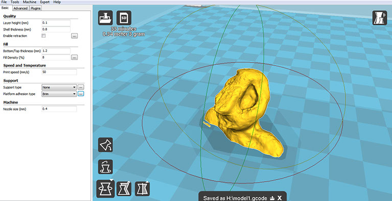
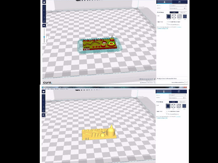
The object is then opened in cura to convert and create G code so that we could load the file and set it for printing
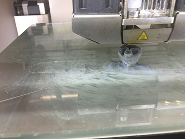
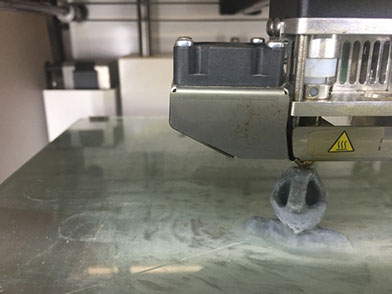
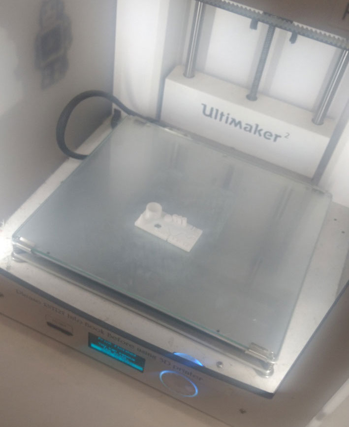
The object was then printed in the scaled down version to save time on the printing as the lab was about to close in few hours. Settings for the print layers height, infill was done in cura and applying a thin line of slurry the print was kept on. I used an ultimaker to print this object.
It was the first time, I was printing a scanned files..will like to try this with other objects too
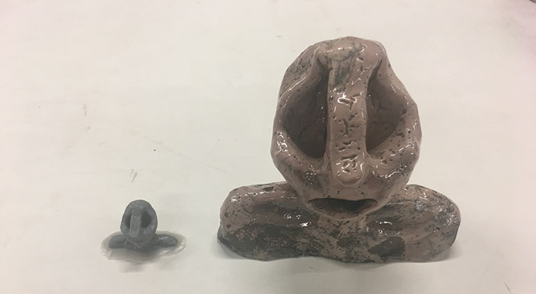
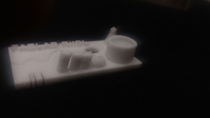
The original object and the 3d printed object
3d printing
3D printing, also known as additive manufacturing (AM), refers to various processes used to synthesize a three-dimensional object. In 3D printing, successive layers of material are formed under computer control to create an object. These objects can be of almost any shape or geometry and are produced from a 3D model or other electronic data source. A 3D printer is a type of industrial robot.
Benefits of 3d printing
Subtractive manufacturing is the process of making an object by removing the material e.g. milling. Use of subtractive manufacturing is not valid in prototyping phase as it takes a lot of time and tool settings. Compared to the 3D printing making tool path, adjusting tool and loading material is the big task compared to additive manufacturing e.g. 3D printing.
My design is simple but making with subtractive manufacturing process will add additional steps of setting up toolpath and tools, as well as it creates lot of waste material which we need to throw.
3D printing is one of the rapid prototyping process which involves the plastic like substance technically ABS or PLA majortly found in these FDM printers. The process of 3D printing is chosen over molding and casting as it takes very less efforts to realize the model. Rather than putting efforts on making mold and casting it one can directly command printer to print a 3D object right from his 3D designing software.
The time involved in the process of making mold and cast it is very large as compared to 3D printing hence printing is preferable for prototyping. But when it comes to manufacturing or mass production 3D printing is not at all useful. The invention of the 3D printer is for testing your proposed model that is prototyping only.
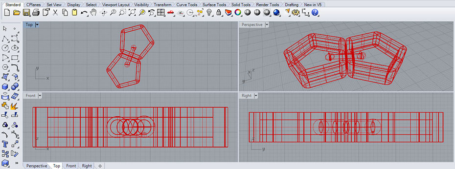
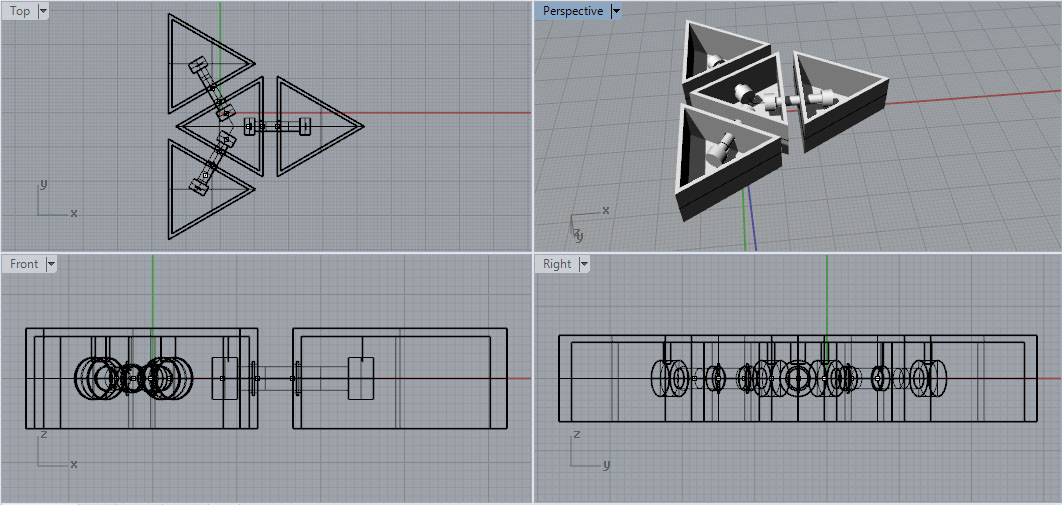
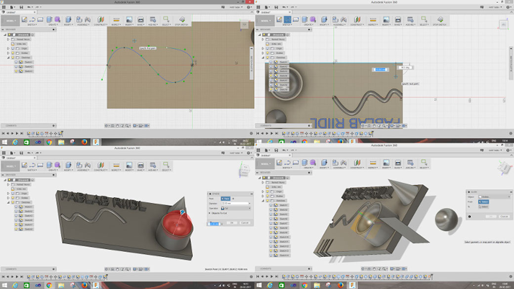
I used Rhino to generate the 3d file my idea was to create a object which has two types of motion. I designed a geometry with a dumble shaped connector which will allow the objects at the end to move linearly as well as rotate about the axis
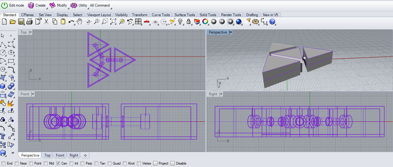
I started with a pentagon shaped flower type structure and failed as the connector stuck to the base..so stopped printing the
structure and decided to pick just two elements and get the printer setting right this time
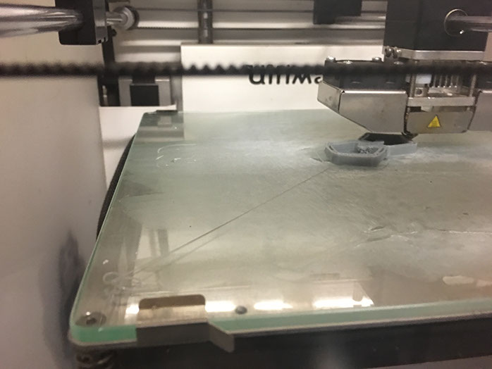
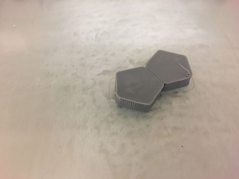
I waited for the entire print to complete and happily tired to rotate the pentagon about the dumble. But due to weak print of the dumble in between the connector broke in this attempt
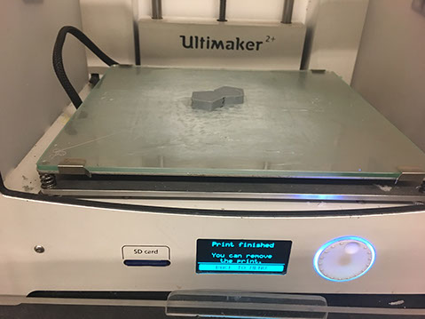
Then I generated supports in the rhino 3d File to correct and put it for print again. This time the upper face was not printed so that I could evaluate the connectors well
ASSIGNMENT 3 : TEST THE DESIGN RULES FOR YOUR PRINTER(S) (GROUP PROJECT)
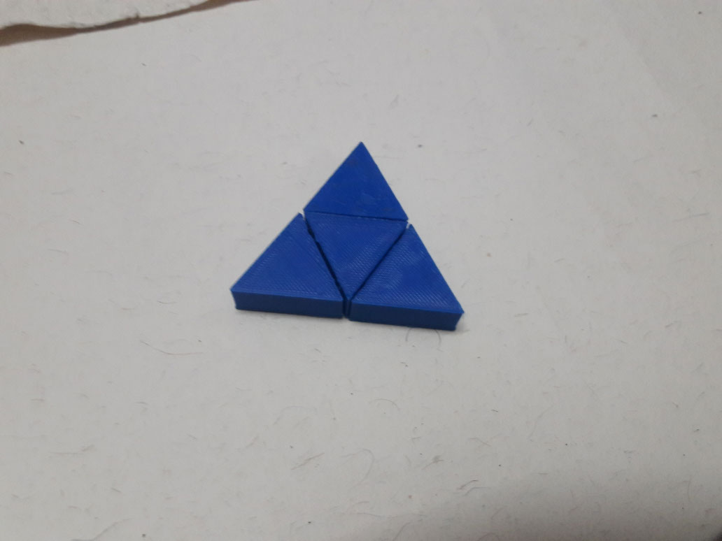
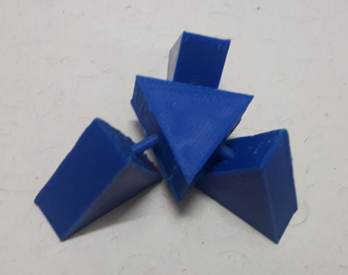
For the group project we decided to make different cutout shapes, extrude, hollow, sharp things to know how 3D printer performed. Sketch is shown in the below image.
This was great fun with the printer. The triangle spinner I call it now!!! Download the file and print from here:
After the files were created they were saved as .stl and opened with cura to set machine parameters and then a G code was generated to be into the machine sd card
The printer was then set and file was printed
By printing this file we got clear idea of the all parameters which could be used for the printing. Thickness, curves, contours, heights, slots, grooves curvature was created in test file
REFERENCES
https://en.wikipedia.org/wiki/Comparison_of_photogrammetry_software
https://remake.autodesk.com/about
CONCLUSIONS
Having 3d printed my project prototypes I had never thought of creating something moving and linked like this earlier. With this week I thought of many other ways I could use the 3D printers to create functional and rapid parts during designing. The group assignments got me versed with all possible parameter that I can create using 3D printed FDM technology
Site created by Lavina Utamani using Adobe Muse | fabacademy 2017