WEEK 15

ASSIGNMENT
1. Make a wired connecting boards.
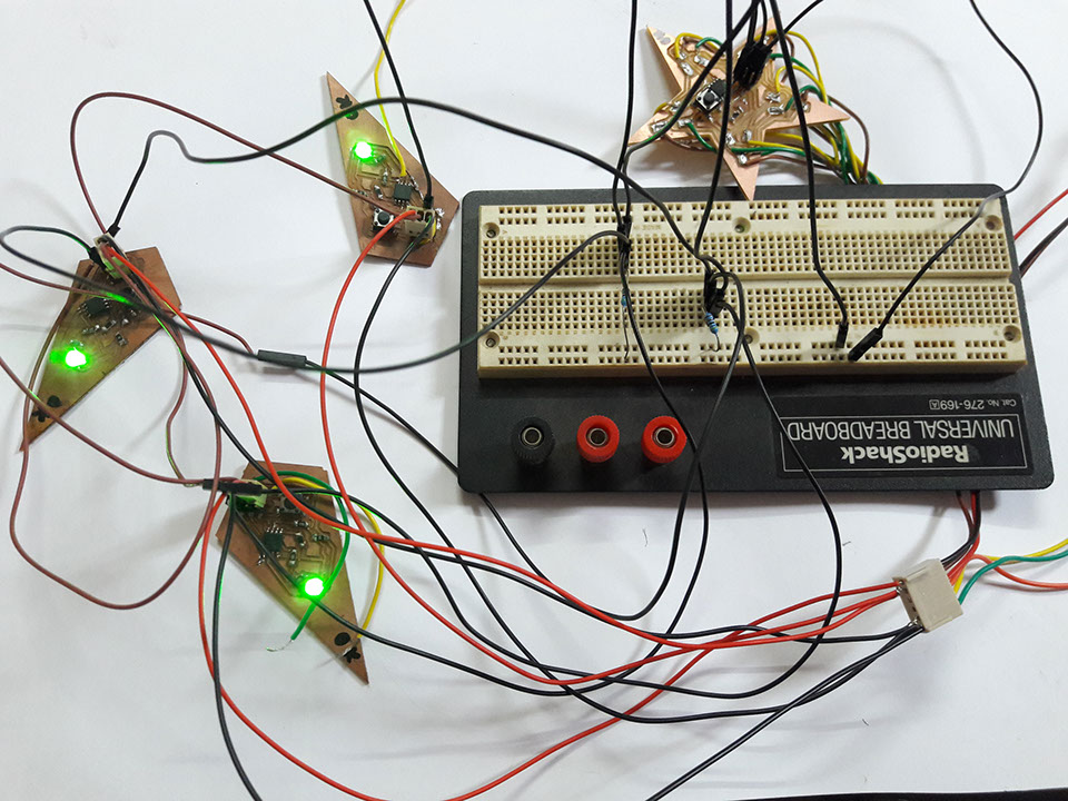
2. Design and build a wired &/or wireless network connecting at least
two processors
Networking and Communication was the most difficult week for me to understand and also it was important to get the concept well for my final project. The toy has five wings and a central star body which acts as the chief communicator
Had to count the number of pins required to select the microprocessor and found that I need the following for the design
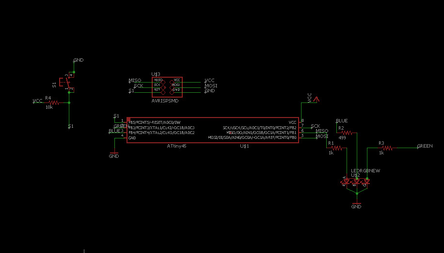
Wing Electronics
RGB LED - 3 pins
Communication - 2 pins
Reset, Vcc and Ground will be others required
Since 5 pins were required I selected Attiny45 for the project
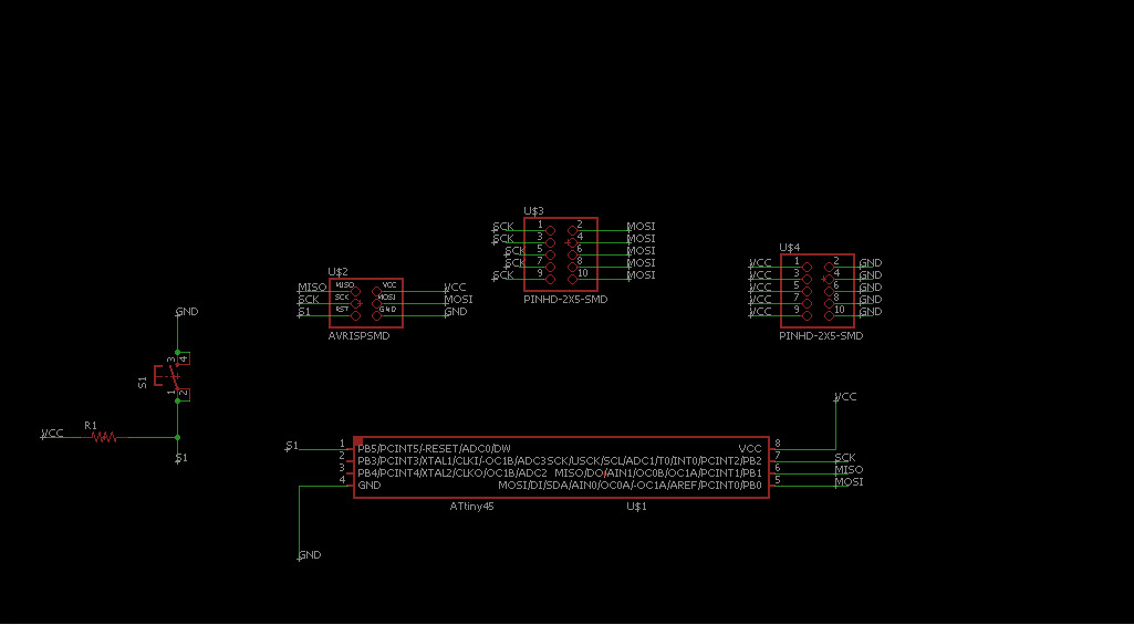
Central Star Body
Communication - 2 pins
Reset, Vcc, Ground will be connected like always
So Attiny45 works for this module of the project
The method of designing will be the same:
1. Design the board with the required components
2. Milling the board
2. Soldering the components
3. Programming of the board through Arduino
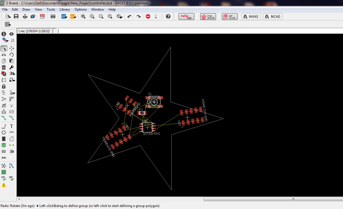
I wanted to shape this as per the toy I designed, I kept trying to draw the shape using tools in Eagle but failed to generate accurate dimensions for the same
Then I found that a .dxf imported to shape and had plenty of complications in routing the design
Required hardware for this assignment:
2 LEDs, each with 200 ohm resistance
2 x 42 Kohm for the I2C BUS (You need them as a pull-up resistor),
A Breadboard with some wires,
The FABISP (check out Week 4 - electronics production),
At least 2 Fabkits V.2, in my example 3 Fabkits V.2,
a FTDI cable,
For central board
// Wire Master LED Writer
// Writes data to an I2C slave device
#include <Wire.h>
void setup() {
Wire.begin(); // join i2c bus (address optional for master)
}
void loop() {
Wire.beginTransmission(5); // transmit to device #5
Wire.write(1); // sends one byte
Wire.endTransmission(); // stop transmitting
Wire.beginTransmission(7); // transmit to device #7
Wire.write(0); // sends one byte
Wire.endTransmission(); // stop transmitting
delay(500);
Wire.beginTransmission(5); // transmit to device #5
Wire.write(0); // sends one byte
Wire.endTransmission(); // stop transmitting
Wire.beginTransmission(7); // transmit to device #7
Wire.write(1); // sends one byte
Wire.endTransmission(); // stop transmitting
delay(500);
}
For the wings
Wire Slave LED Receiver
#include <Wire.h>
void setup() {
pinMode(A3, OUTPUT);
Wire.begin(5); // join i2c bus with address #5
Wire.onReceive(receiveEvent); // register event
}
void loop() {
delay(100);
}
// function that executes whenever data is received from master
// this function is registered as an event, see setup()
void receiveEvent(int howMany) {
int x = Wire.read(); // receive byte as an integer
if (x == 0)
digitalWrite(A3, HIGH);
else
digitalWrite(A3, LOW);
}
// Wire Slave LED Receiver
#include <Wire.h>
void setup() {
pinMode(A3, OUTPUT);
Wire.begin(7); // join i2c bus with address #7
Wire.onReceive(receiveEvent); // register event
}
void loop() {
delay(100);
}
// function that executes whenever data is received from master
// this function is registered as an event, see setup()
void receiveEvent(int howMany) {
int x = Wire.read(); // receive byte as an integer
if (x == 0)
digitalWrite(A3, HIGH);
else
digitalWrite(A3, LOW);
}
References
I would like to refer to page Arduino.cc and www.hlembke.de which has helped me very much to get the necessary information.
Site created by Lavina Utamani using Adobe Muse | fabacademy 2017