ASSIGNMENT
1. Measure something: add a sensor to a micro controller board that you
have designed and read it
Devices which perform an “Input” function are commonly called Sensors because they “sense” a physical change in some characteristic that changes in response to some excitation, for example heat or force and covert that into an electrical signal.
This week I wanted to learn and understand arduino programming throughly so I designed a pcb with the attiny 45 and then see the working of the ultrasound sensor
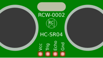
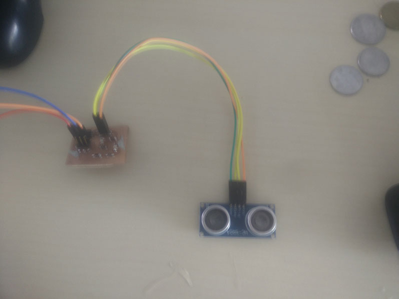
Ultrasonic Sensor (HC-SR04) - Analog Mode
There are two tranducers, one to transmit and one to receive. Two transducers turn out to be cheaper, since a higher voltage is needed to transmit and switching modes using only one transducer takes a lot of analog circuitry.
Select the pulse mode by removing the shunt from the operating mode selection jumper. Connect the Trig/TX pin to a digital output on your microcontroller and the Echo/RX pin to a digital input. To obtain a distance measurement, set the Trig/TX pin high for at least 50 microseconds then set it low to trigger the measurement. The module will output a high pulse on the Echo/RX line with a width that corresponds to the distance measured. Use your microcontroller to measure the pulse width using microseconds. Use the following formula to calculate the distance:

As seen in the timing diagram above, only two signal pins are used. Trigger starts a measurement cycle and sends out a short ultrasonic pulse (eight cycles at 40Khz) and then listens for a reflected signal (echo). Several cycles at 40Khz are needed for the analog receiver circuit to detect the reflected signal. The width of the echo pulse output pin indicates distance. A hardware timer would typically be used to measure the echo pulse width. A simple divide operation can then scale the value to cm or inches, if needed.
Ultrasonic Sensors are self-contained solid-state devices designed for non-contact sensing of solid and liquid objects. For many applications, such as monitoring the level of water in a tank, ultrasonic technology lets a single device to do a job that would otherwise require multiple sensors. This module includes ultrasonic transmitters, receiver and control circuit. It's 4 pinned device requies 5V DC Supply and a working current of 15mA. It has a maximum range of 4m and minimum range of 2cm. The four pins are 5V Supply, Trigger Pulse Input, Echo Pulse Output, 0V Ground.
The device should not be triggered again until waiting for the longest possible echo return time delay (maximum detection distance times speed of sound in air). This prevents any echos from the previous ultrasonic pulse interfering with the next pulse measurement or the new outgoing pulse being heard as the echo from the previous pulse. Something a bit over 10 measurements per second is typical on most small sonar sensors. The HC- SR04 data sheet suggests a min cycle time of 60 ms.
Steps involved are :
1. Design the board with the required components
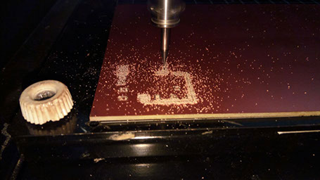
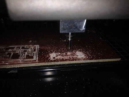
2. Milling the board
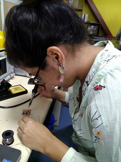
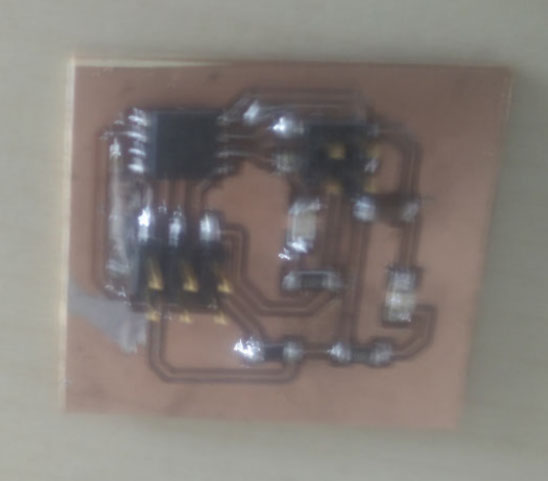
2. Soldering the components
3. Programming of the board through Arduino
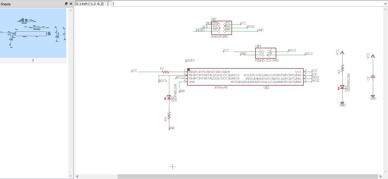
I had by know understood the basics well for using Eagle to design the board.... so I created a new project and started adding the components of the board and generated a schematic design for the input devices as follows
Soldering the components on the board
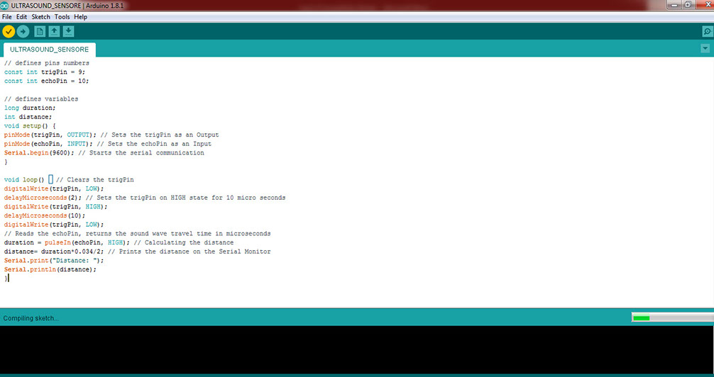
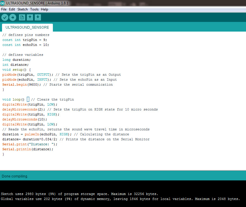
Programming of Ultrasonic Sensor:
// defines pins numbers
const int trigPin = 9;
const int echoPin = 10;
// defines variables
long duration;
int distance;
void setup() {
pinMode(trigPin, OUTPUT); // Sets the trigPin as an Output
pinMode(echoPin, INPUT); // Sets the echoPin as an Input
Serial.begin(9600); // Starts the serial communication
}
void loop() { // Clears the trigPin
digitalWrite(trigPin, LOW);
delayMicroseconds(2); // Sets the trigPin on HIGH state for 10 micro seconds
digitalWrite(trigPin, HIGH);
delayMicroseconds(10);
digitalWrite(trigPin, LOW);
// Reads the echoPin, returns the sound wave travel time in microseconds
duration = pulseIn(echoPin, HIGH); // Calculating the distance
distance= duration*0.034/2; // Prints the distance on the Serial Monitor
Serial.print("Distance: ");
Serial.println(distance);
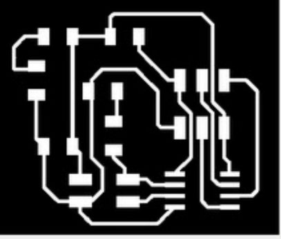
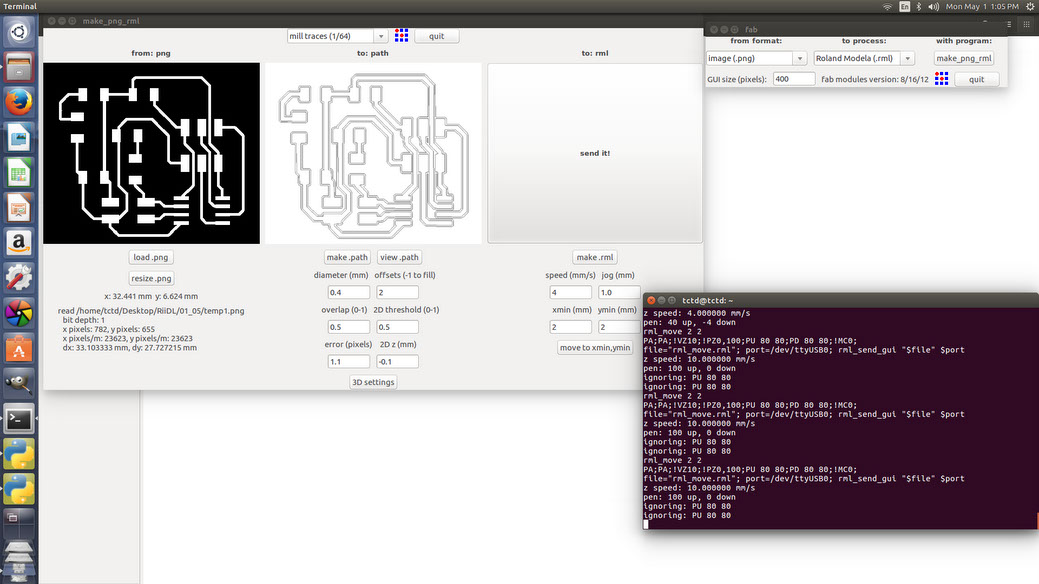
Then saving the png image of the design which will be used for milling the board creating .rml file for the board to be milled. 1/64 mill traces were set and the board was set to be milled
Site created by Lavina Utamani using Adobe Muse | fabacademy 2017
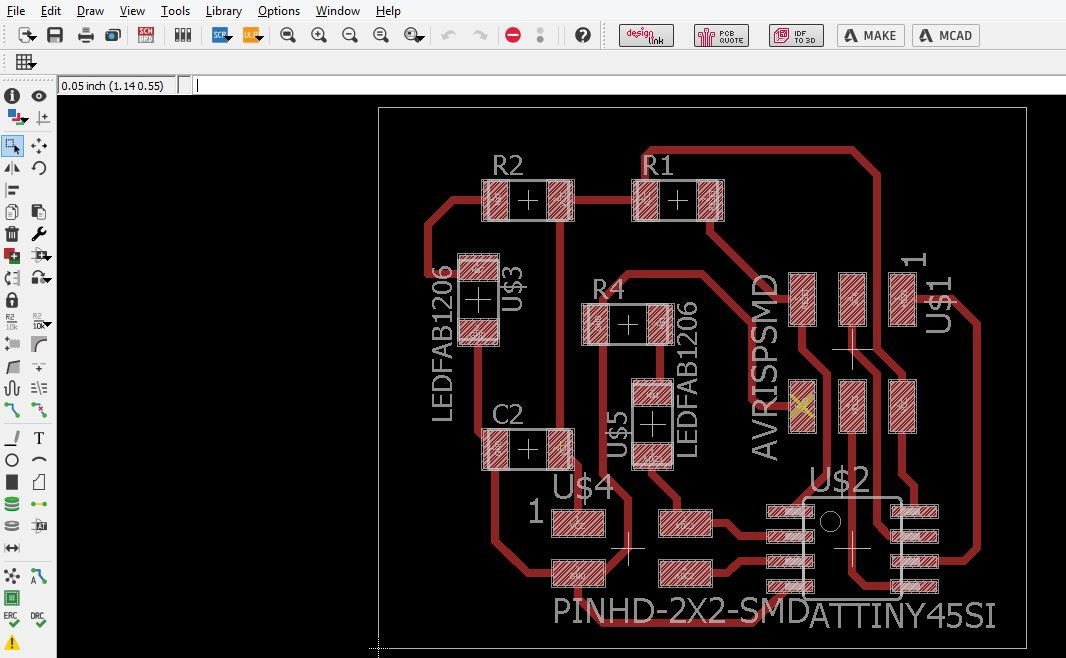
Then following the steps checked the schematic and moved to designing the PCB board