ASSIGNMENT
1. Add an output device to a microcontroller board you've designed and
program it to do something
This is week assignment is to make a microcontroller board which can be used to control an output device. There are different type of output devices are available like LED, Speakers,LED arrays, RGB LED, LCD,OLED,Servo & stepper motors etc. I selected a servo motor as my output device
To begin with I got started by understanding various kinds of motor and how they function
A servomotor is a rotary actuator or linear actuator that allows for precise control of angular or linear position, velocity and acceleration. It consists of a suitable motor coupled to a sensor for position feedback. It also requires a relatively sophisticated controller, often a dedicated module designed specifically for use with servomotors. Servomotors are not a specific class of motor although the term servomotor is often used to refer to a motor suitable for use in a closed-loop control system.
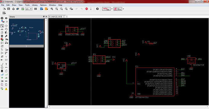
As my first step to design the board, I selected the required components for the library. I kept the board image from the tutorial for my reference. Next step was to add connections between the components. I made the schematic diagram while understanding the circuit. So it was easy to do the same in EAGLE and completed schematic diagram for the board
The image shows the schematic diagram in process.
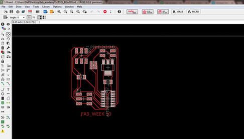
As a regular practice by now, moved to designing the board by changing the mode. adjusted all the components to create a compact layout and then decided to auto route the board like shown in the image below. Drew a border line outside for the cutting to happen by keeping sufficient distance
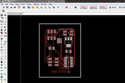
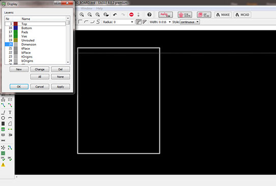
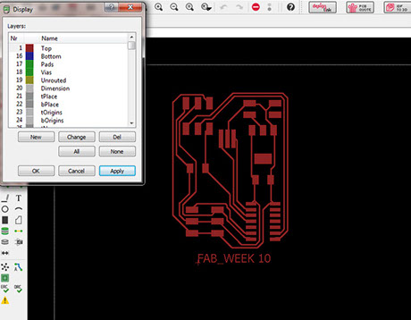
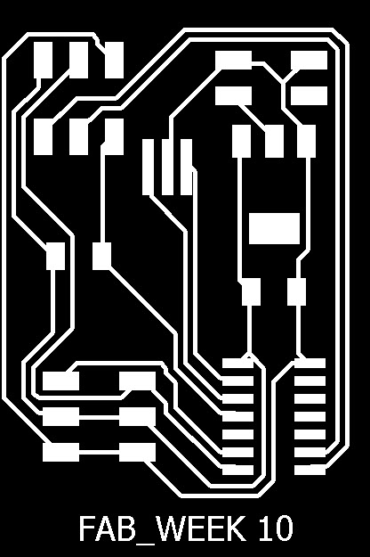
Once the design of the board is complete the next task is to create png images for the milling process to begin. Select just the top layer and export a png image of the board design and keep dimensions selected while creating png for the cut out of the board
Exported png images of the board and cut out border

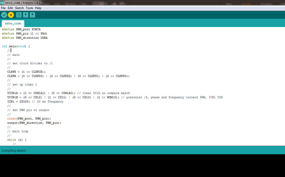
//
// hello.servo.44.c
//
// servo motor hello-world
//
// set lfuse to 0x5E for 20 MHz xtal
//
// Neil Gershenfeld
// 4/8/12
//
// (c) Massachusetts Institute of Technology 2012
// This work may be reproduced, modified, distributed,
// performed, and displayed for any purpose. Copyright is
// retained and must be preserved. The work is provided
// as is; no warranty is provided, and users accept all
// liability.
//
#include <avr/io.h>
#include <util/delay.h>
#define output(directions,pin) (directions |= pin) // set port direction for output
#define set(port,pin) (port |= pin) // set port pin
#define clear(port,pin) (port &= (~pin)) // clear port pin
#define pin_test(pins,pin) (pins & pin) // test for port pin
#define bit_test(byte,bit) (byte & (1 << bit)) // test for bit set
#define position_delay() _delay_ms(1000)
#define PWM_port PORTA
#define PWM_pin (1 << PA6)
#define PWM_direction DDRA
int main(void) {
//
// main
//
// set clock divider to /1
//
CLKPR = (1 << CLKPCE);
CLKPR = (0 << CLKPS3) | (0 << CLKPS2) | (0 << CLKPS1) | (0 << CLKPS0);
//
// set up timer 1
//
TCCR1A = (1 << COM1A1) | (0 << COM1A0); // clear OC1A on compare match
TCCR1B = (0 << CS12) | (1 << CS11) | (0 << CS10) | (1 << WGM13); // prescaler /8, phase and frequency correct PWM, ICR1 TOP
ICR1 = 25000; // 20 ms frequency
//
// set PWM pin to output
//
clear(PWM_port, PWM_pin);
output(PWM_direction, PWM_pin);
//
// main loop
//
while (1) {
//
// 1 ms PWM on time
//
OCR1A = 1250;
position_delay();
//
// 1.5 ms PWM on time
//
OCR1A = 1875;
position_delay();
//
// 2 ms PWM on time
//
OCR1A = 2500;
position_delay();
}
}
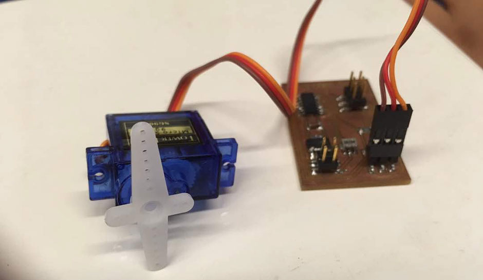
Click on the image below on see the video
REFERENCES
CONCLUSION
Output devices week was very useful week as many projects required motor to be controlling. This could be extremely useful while creating robos
Design Files
Board_schematic
Board_design
Board_png
Board_cutout
Site created by Lavina Utamani using Adobe Muse | fabacademy 2017