Home
FINAL PROJECT
TWINKLE TRICKS
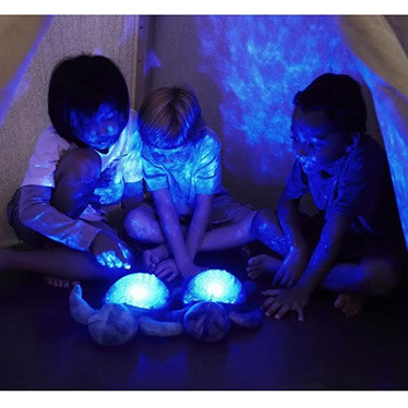
Twinkle Tricks is a NO button electronic toy designed for improving gross motor activities of children specially affected with autism. The toy has amazing visual perception in combination of sound and projections that please their vision surprising the child each time he/she plays with it. The unique magnetic switches allows to let a unique combination code to function in a radial pattern. The color combination to aesthetic details of the toy in created to celebrate the childhood
INSPIRATION
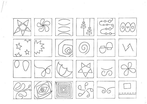
Surprise is the element of inspiration for designing a toy of an autistic child. So the two drawing below are inspired from stars, flowers, gifts which mean surprise to children in general
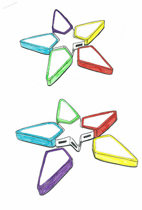
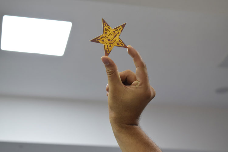
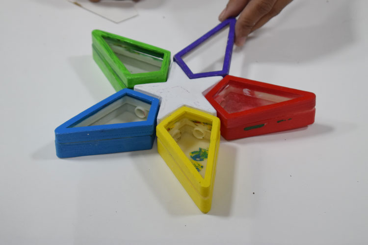
The star was selected from the drawing above and a lego pattern is planned for the toy
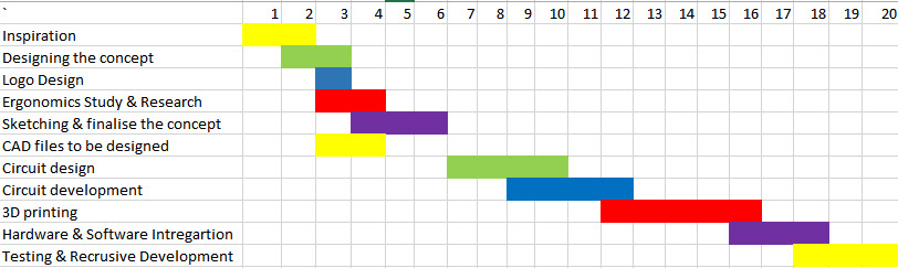
Timeline
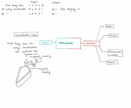
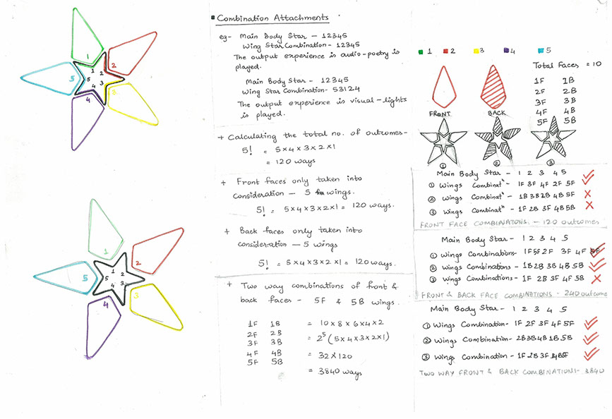
To decide on the working, I calculated some combination patterns and decided it to be screen only on the front side and 120 outcomes will be possible to create... in which repeated patterns will make sense so just 10 patterns was decided to be worked on
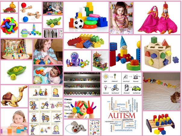
ABOUT AUTISM
Studying Therapy methods for autistic children I founded that Twinkle tricks had potential to improve Visual Motor Planning And sensaory imagination


Ergonomic Study of children's and data ensured about the dimensions selected for the toy
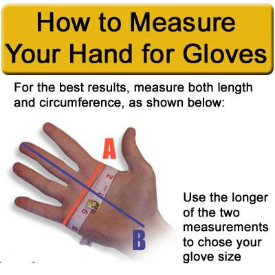
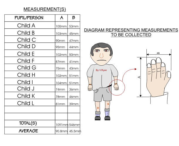
Dimensions calculated by the ergonomic study were used to define the size of the star around
80*80*25 so the child could grip the toy well and the wing was calculated to be around 60*80*25
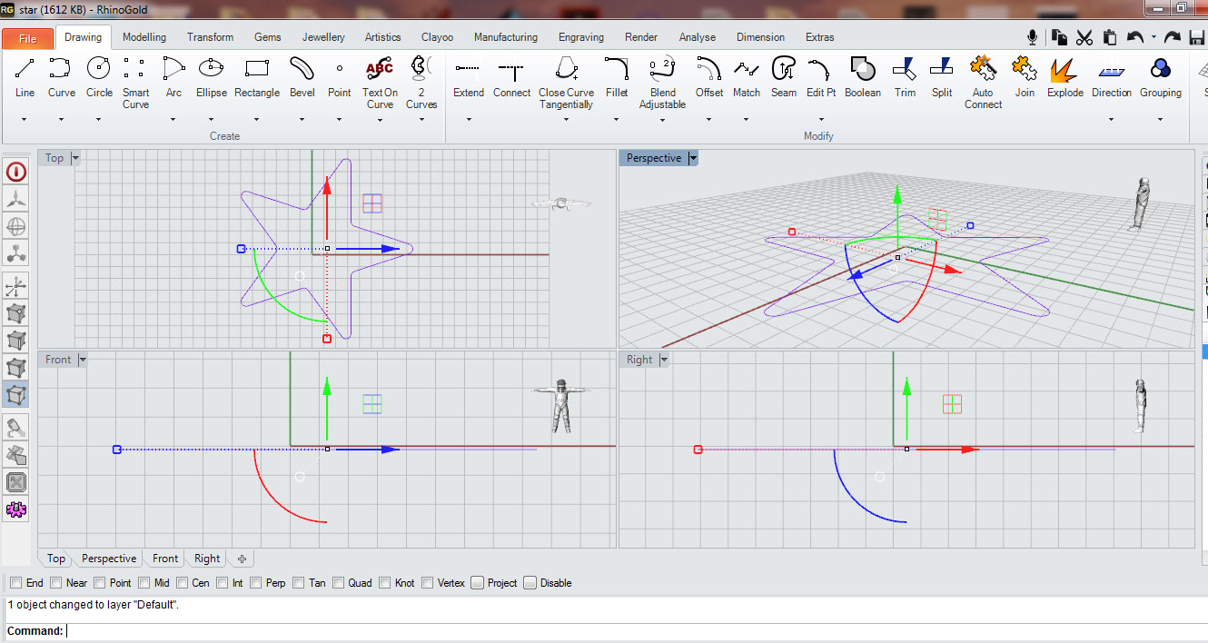
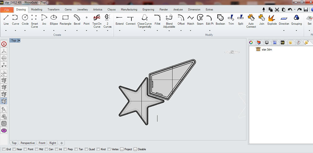
Using this overall dimensions and prototype of paper helped me generate 3d files for printing the toy. Rhino was used to design the files and then the .3dm files were converted to stl and then converted to gcode into cura
Press fit was designed in accordance to lock the base and cap of the toy parts. the toy has 4 unique parts to be designed:
Star_cap
Star_base
Wing_cap
Wing_base
The parts generates were saved separately into stl files and printed on the ultimaker using G code generated in cura refer to week 3 for the process
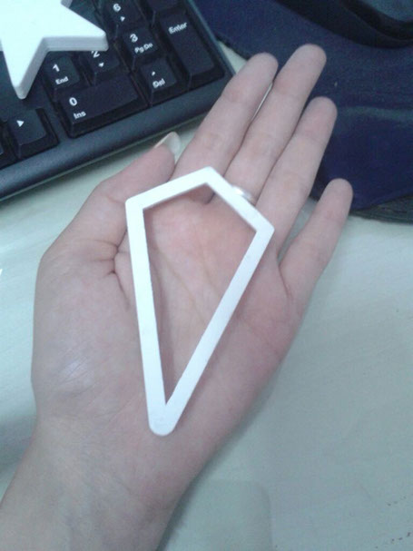
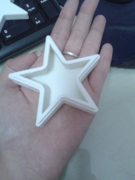
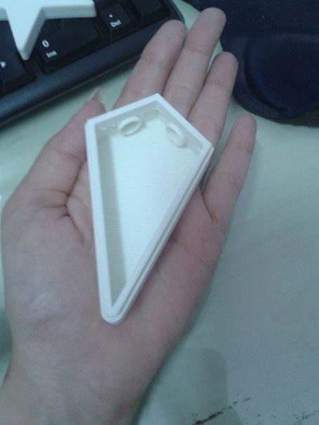
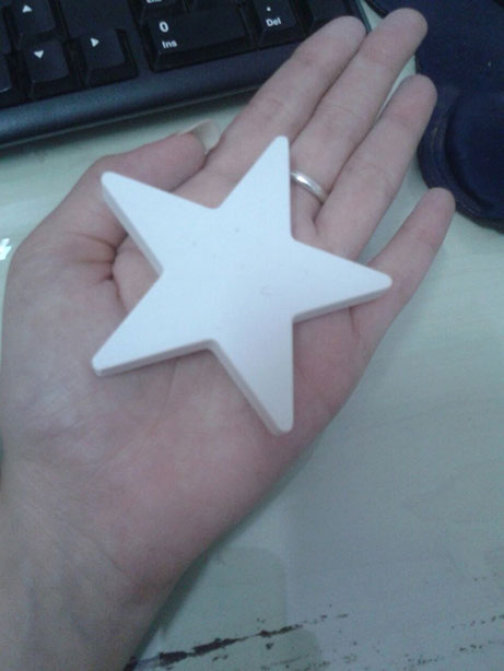
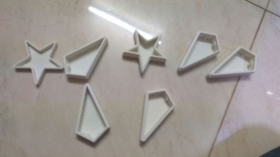
The parts of the toy were successfully printed but was time consuming as there were many parts to print
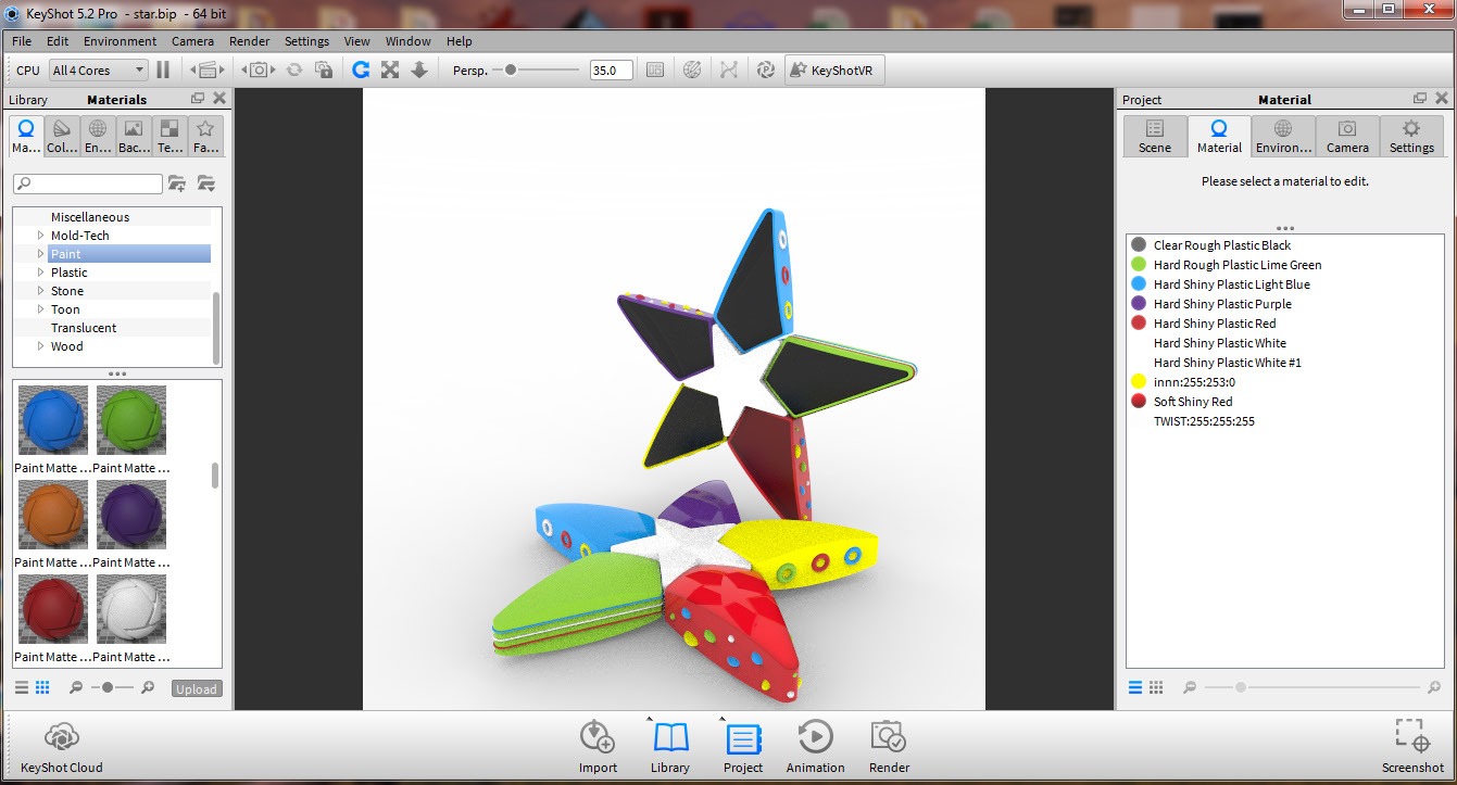
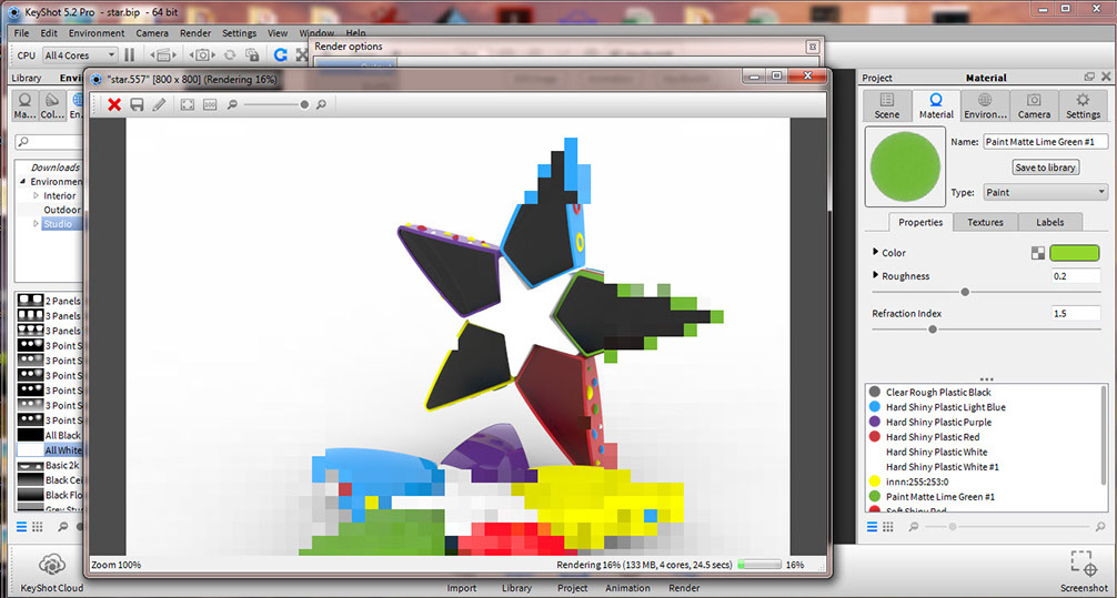
Keyshot was used simultaneously to generate the look like of the toy by rendering with different materials. This software is very easy to use ..just Pick and drop the material of the object you wish to render
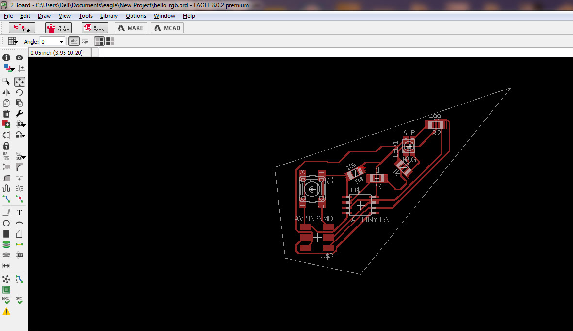
Designing the electronics for this I started with basic square shaped board which could diagonally be set into the wing and milling the first board for the project, the border generated was incorrect the board track was cut after milling. I had to repeat the milling of the board then by correcting the border and then solder the components on the board
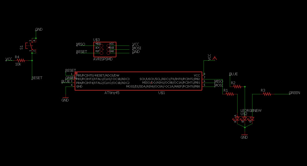
This schematic was the generated but my friend pointed out the mistake in the rgb led connections, so corrected the schematic before the designing of the board

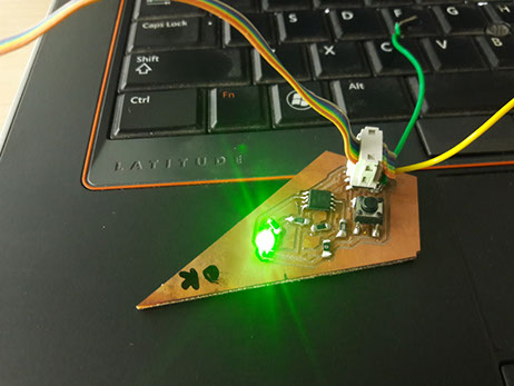
Testing the board with the basic led blink test code on the boards using the FabISP
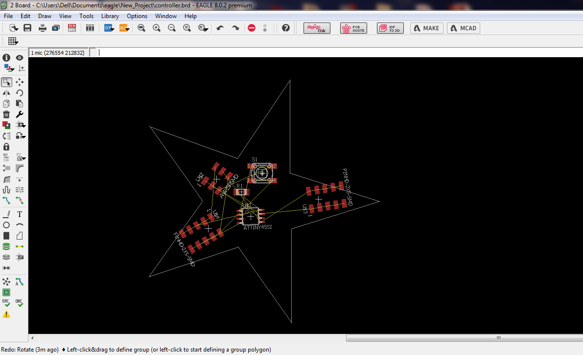
Central board was also design with an attiny 45 it control the identification of the wing for resistive network
For each board I changed the pattern of the led blinking was varied.. the delay time of the led blink was changed
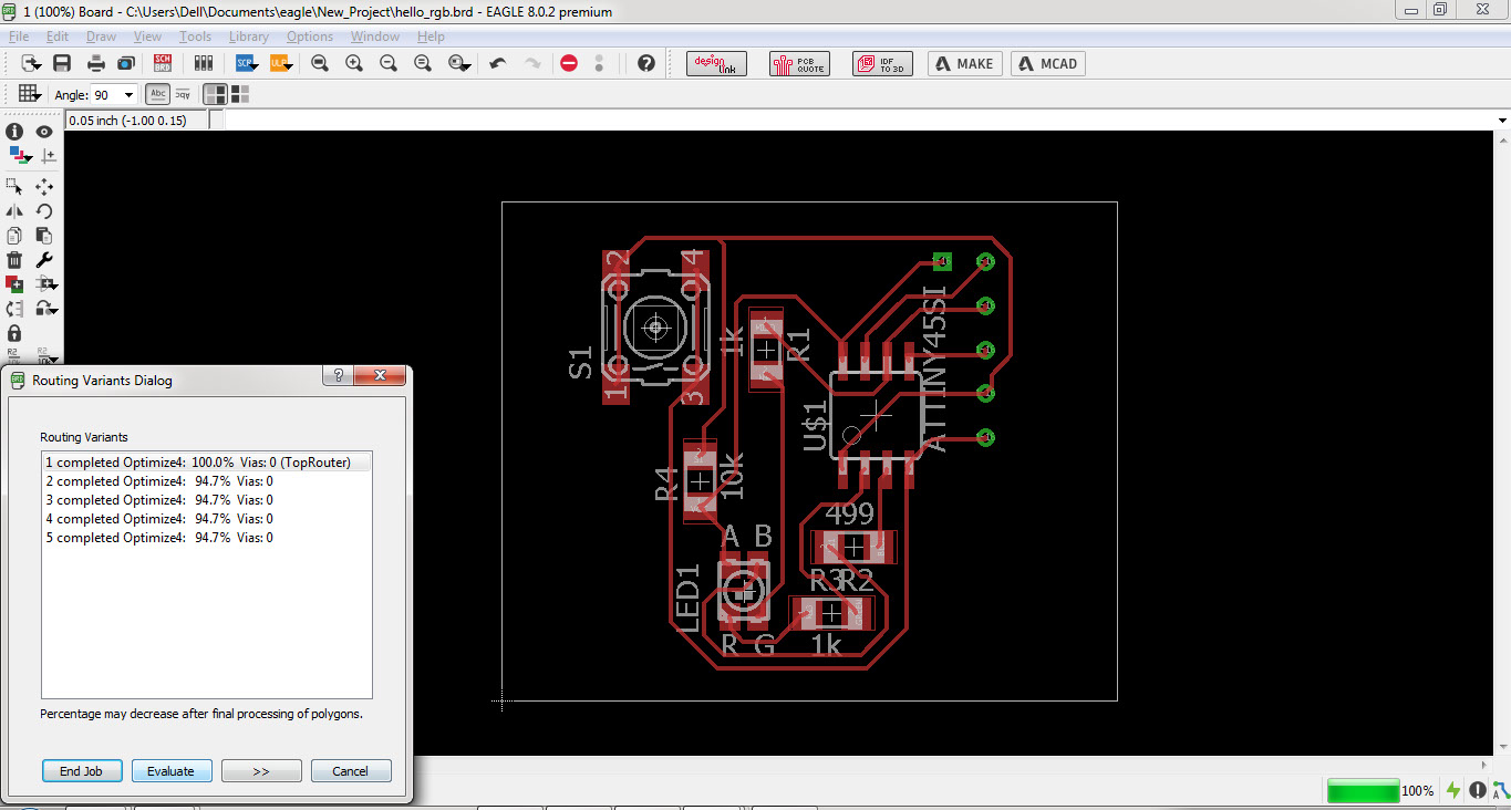
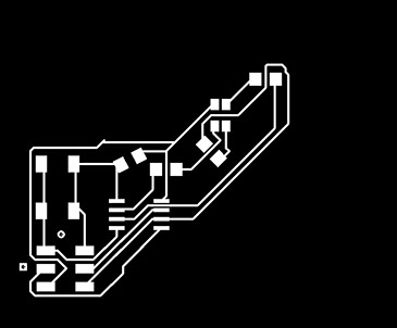
Once the board design was ready, png images of the board milling and cutout were exported. These exported images were
then opened into fab mods and a .rml file was generated to begin the milling process
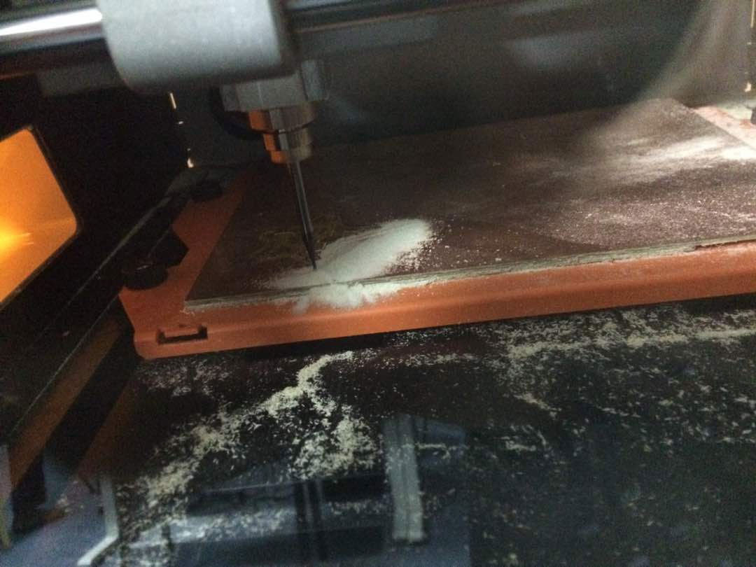

Cool tip from the instructor to check the milling tracks properly before soldering components was to see it in light or use mobile torch to check the boards
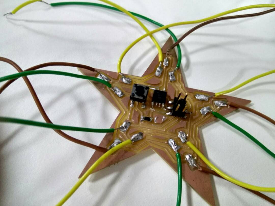
Soldering the board with components like shown below
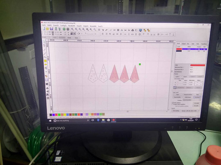
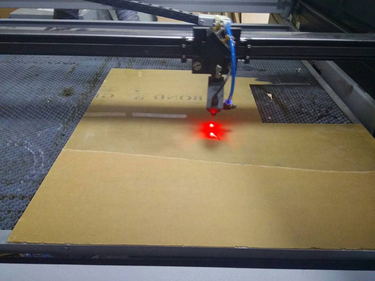
Laser cutting the acrylic sheet transparent 1mm thick to create screens for the wings of the star network
Assembling the screen on the wing cap like shown below
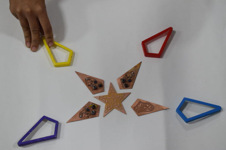
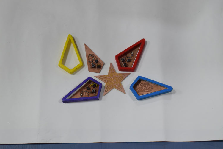
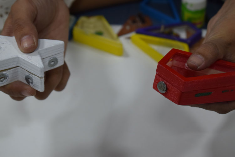
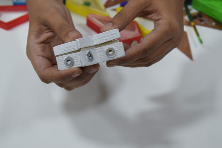
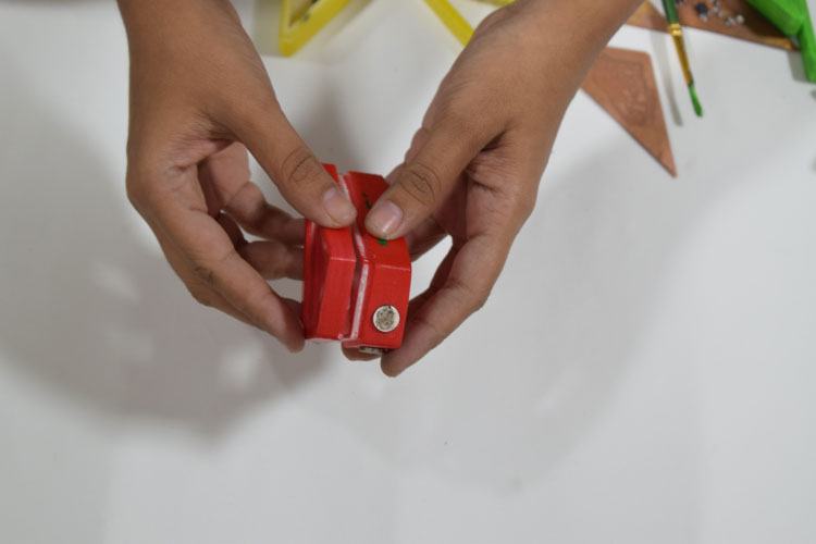
Accumulating all the components and keeping them ready for final assembly. The star is painted with Acrylic colors in the five different shades. The boards are replicated and produced for all wings. The Magnets are stuck to the wings as planned and washer which are magnetic on the central body are stuck. These connector are then covered with copper tape to generate electronic connect
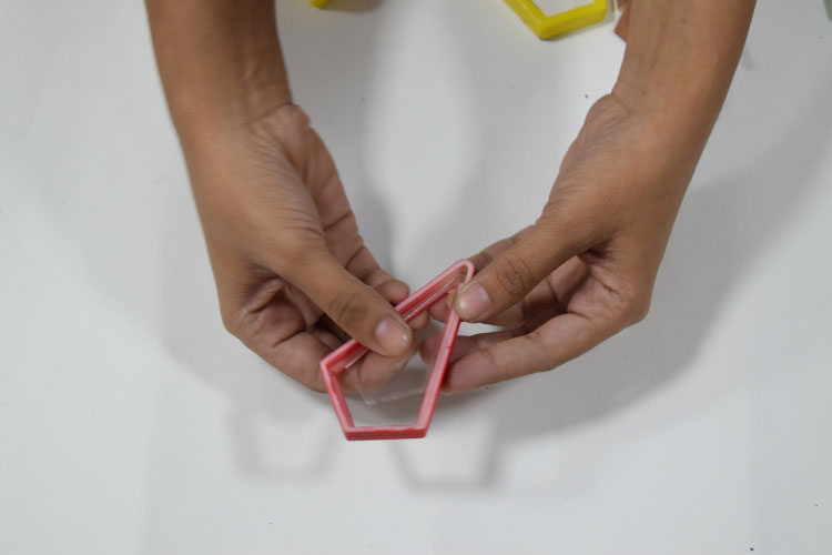
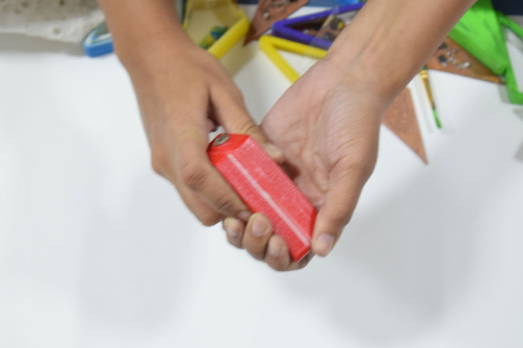
Testing the magnetic lego and then loading the electronics to the wings for the final assembly
Load the final electronics and pack the wings. Repeat for all the wings
I prepared the codes to run the board.The codes I used are attached below and the video showing the working of the code can be seen beneath the codes.
// codes for Twinkle Tricks
// codes by Lavina Utamani
//http://archive.fabacademy.org/archives/2017/fablabriidl/students/357/
code for wing 1, wing 2, wing 3
// the setup function runs once when you press reset or power the board
void setup() {
// initialize digital pin LED_BUILTIN as an output.
pinMode(LED_BUILTIN, OUTPUT);
}
// the loop function runs over and over again forever
void loop() {
digitalWrite(LED_BUILTIN, HIGH); // turn the LED on (HIGH is the voltage level)
delay(1000); // wait for a second
digitalWrite(LED_BUILTIN, LOW); // turn the LED off by making the voltage LOW
delay(1000); // wait for a second
}
Code for Wing 4 and wing 5
This code only works for common anode leds.
#define GREEN 2
#define BLUE 3
#define RED 6
#define delayTime 30
void setup() {
pinMode(GREEN, OUTPUT);
pinMode(BLUE, OUTPUT);
pinMode(RED, OUTPUT);
digitalWrite(GREEN, HIGH);
digitalWrite(BLUE, HIGH);
digitalWrite(RED, HIGH);
}
int redVal;
int blueVal;
int greenVal;
void loop() {
int redVal = 255;
int blueVal = 0;
int greenVal = 0;
for( int i = 0 ; i < 255 ; i += 1 ){
greenVal += 1;
redVal -= 1;
analogWrite( GREEN, 255 - greenVal );
analogWrite( RED, 255 - redVal );
delay( delayTime );
}
redVal = 0;
blueVal = 0;
greenVal = 255;
for( int i = 0 ; i < 255 ; i += 1 ){
blueVal += 1;
greenVal -= 1;
analogWrite( BLUE, 255 - blueVal );
analogWrite( GREEN, 255 - greenVal );
delay( delayTime );
}
redVal = 0;
blueVal = 255;
greenVal = 0;
for( int i = 0 ; i < 255 ; i += 1 ){
redVal += 1;
blueVal -= 1;
analogWrite( RED, 255 - redVal );
analogWrite( BLUE, 255 - blueVal );
delay( delayTime );
}
}
CONCLUSIONS
It was really a good exercise to make the projects work with everything you could do yourself it was really a great deal of energy
experienced to see something you worked long way to work and some idea converted to a working project. With this I will surely try and improve on the project in near future as well as take up other projects. I really thank everyone associated to help me, upgrade my skill set each day and finally have the project working.
Fabacademy Digital Fabrication course is an excellent platform to learn, connect and discover the power to make anything you desire
Site created by Lavina Utamani using Adobe Muse | fabacademy 2017