Goal of the assignment
In this assignment we need to interface our board with the Computer. i.e. we need to control our board with the computer by making a GUI which will be used to give command to the board via the USB Cable/ USB to UART in my case.
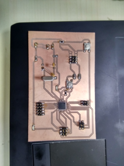
I have prepared the final PCB board which I am going to use for my final project and for this assignment. The board is same as the Arduino UNO Board because it has the same IC i.e. 328p, and does all the functionality of UNO.
For this assignment I have used my batchmate gaurang board.
Below are the images of the final board
- PNG image of the board file which is will be given to the moldela for the PCB fabrication.
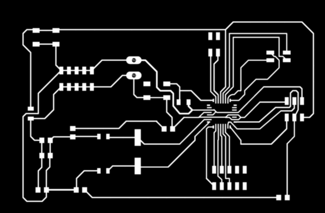
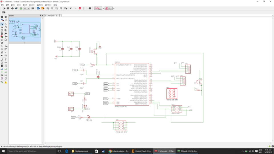
- Schematic images of the board which was made in the Eagle software.
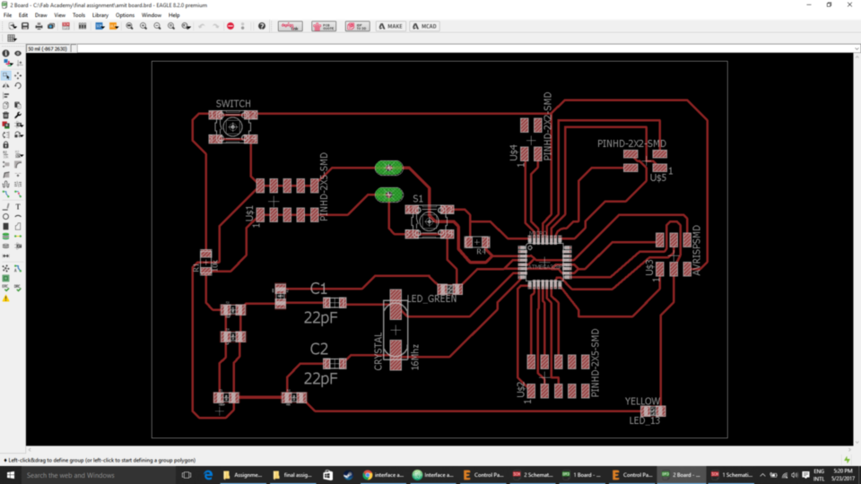
- Board images of the final PCB.
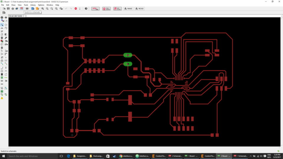
- Image of the board after milled.
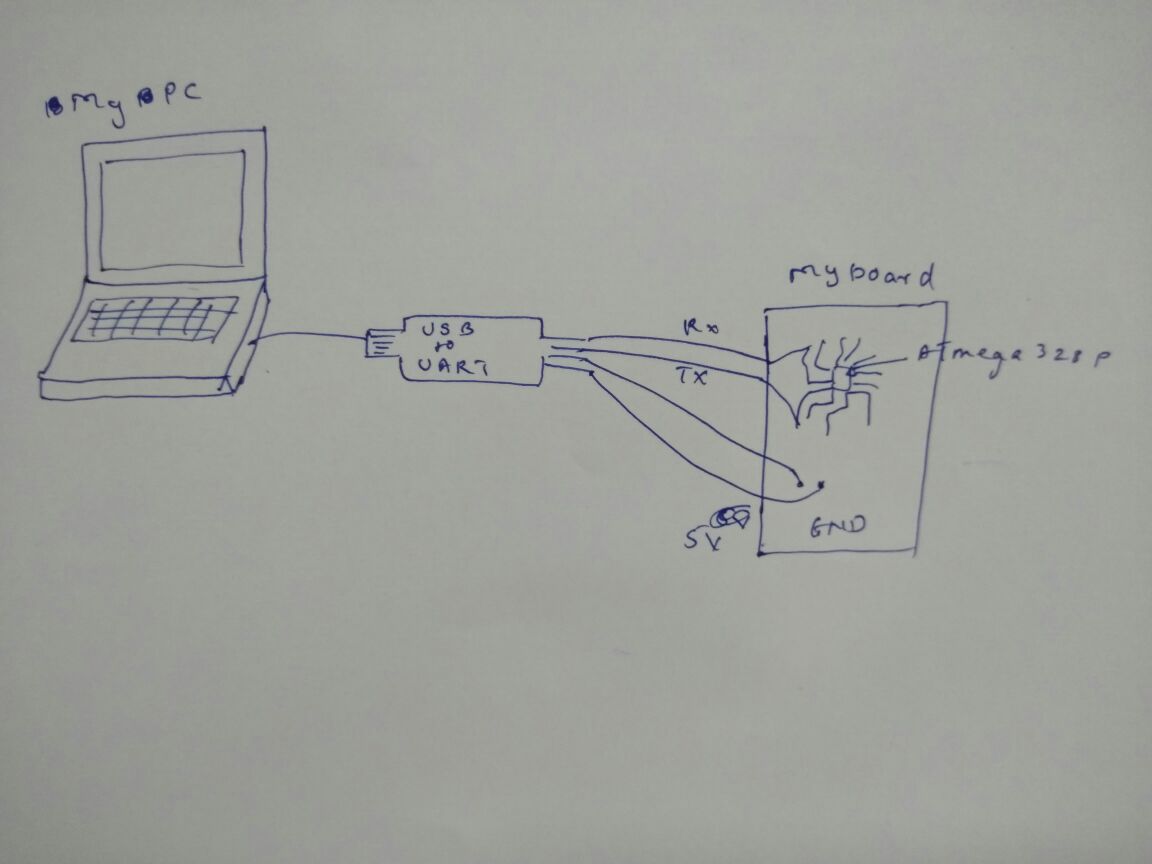
Connection diagram
Now for the assignment is have used Processing as interfacing program between the board and PC.
what really happing in the program?
what processes are running?
-->> I written a code in which when we hover our cursor on the buttons of the dialog box the led will turn ON and OFF.
The processing is communicating with my board through serial communication, which is done by USB to UART converter, the processing is communicating through COMPORT.
When processing needs to turn ON the led it send "port.write('1')" to my board, and to turn OFF it sends "port.write('0')".
At the receiving end my board reads command by "Serial.read()" function.
.png)
Below is the image of the Processing IDE
What I have done in this assignment!!!
Working between progessing and Arduin IDE
- I made a GUI with the help of processing which can turn ON and OFF the led which is connected to digital pin 13 on the board when we hover the mouse button on the virtual button.
Below are the images of the processing program. .
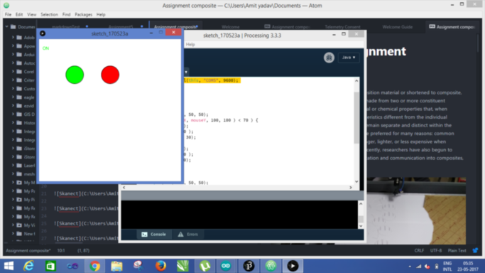
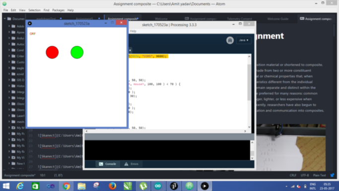
- I have used the Arduino IDE for programming the board. In the code, the led which is on pin 13 on the board will be ON when the mouse is hovering on the first button and will be OFF when the mouse is hovering on the second button.

- This is the connection diagram in which I used USB to serial converter to upload the Arduino code to the board and to get me the port address so that I can connect it with the processing for run the program.
- The program flow is as follows:
1. When we Hover on one of the buttons of the processing program, the LED will glow on the board.
2. When we on the hover on the other button of the processing program the LED will glow off.
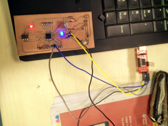
- There is the final output video: when I am hovering the mouse on the between the two buttons the led is glowing on the board.