CIAS
Crash Instant Alert System
Inspiration
There are many accident happen in Mumbai due to small roads, so when people meet with an accident they don't have any kind of system to inform their loved ones so that they can come and help them or at least acknowledge them about their condition.
Flowchart
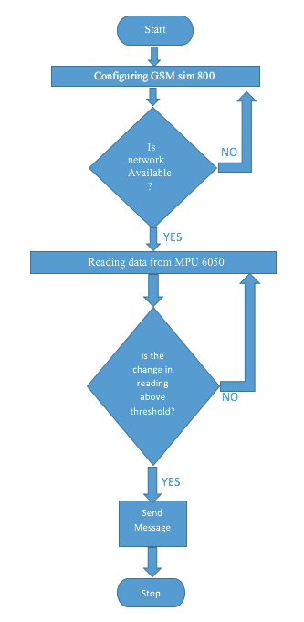
The process flow as:
1. The kit will search for the network.
2. After register to the network it will start readign the MPU 6050 data.
3. As soon as the data from the MPU 6050 goes below the threshold it will start sending the data to the loved ones or
the registered number which in installed on the kit.
Project planning Gantt chart
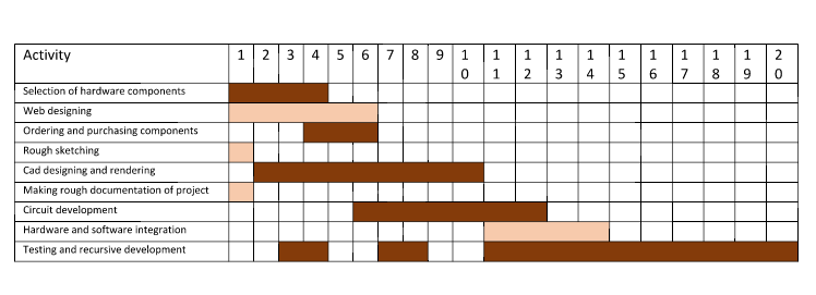
Hardware Development
These are the development that I have done while making the final project.
- Micro-controller (Atmega 168/328) - I have redesigned the shatsha kit for my final project which I have explained in the output devices asssigment.
- Screen (a ouput device)
- Communication Device (GSM Modem SIM800)
- Battery
Sketch of the proposed hardware
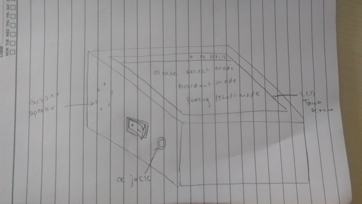
Device / Sensor
Micro-controller:
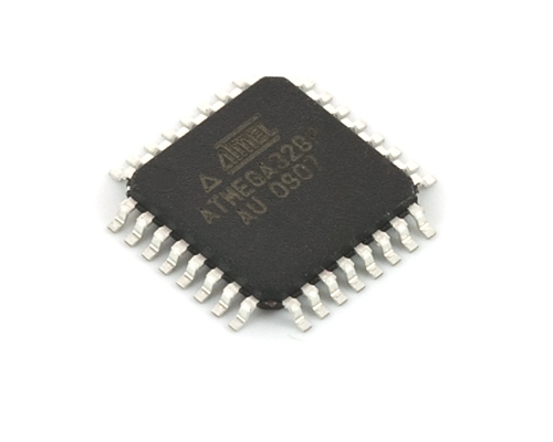
I'll be using custom designed Atmega 168 or 328 board, which is specially developed to have interfacing pin outlay to get connected to peripherals(keypad, LEDs, GSM Modem). GPIOs pins will be connected to the keypad which is 4X4 keypad which can be used to enter the user credentials and the amount during the transaction. The reason behind choosing the Atmega 328 or 168, first both micro-controller is compatible with Arduino IDE which makes the coding process quite easy on top of that it has got some extra pins to attach the extra components other than what is planned, that's what I have extra room to expand capabilities of POS.
Screen:
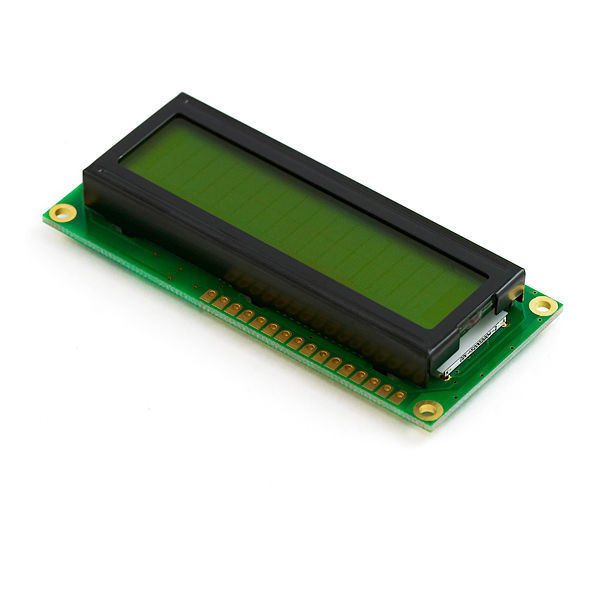
The screen is placed on POS to give prompt the user about the process which is taking place. It will show the vital messages and instructions to carry out the process. I'll be using 16X2 lcd which is commonly available in market and pretty ease to interface with micro-controller. 16X2 LED display has two methods to make it work, one is 8-bit mode and other is 4-bit mode. I'll be using 4-bit mode which will reduce the overhead of connections resulting into easy to troubleshoot.
Communication Device:
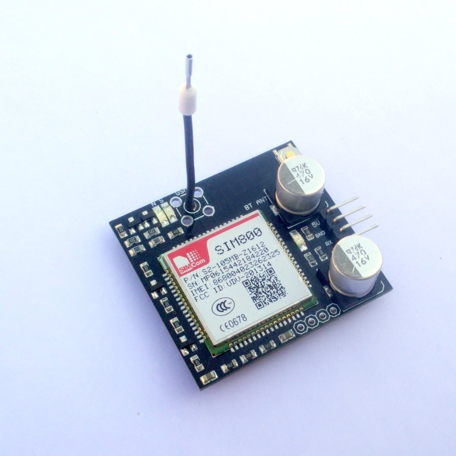
To make the device enable to get connected to cloud POS will take the help from the fellow SIM800. SIM800 is the simcom's product which is the GSM/GPRS module. I'll be using some ready made PCB available on Amazon or at local retailer to make the project development easier.
Sensing:
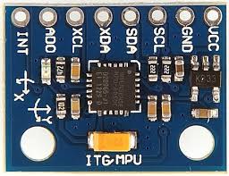
The InvenSense MPU-6050 sensor contains a MEMS accelerometer and a MEMS gyro in a single chip. It is very accurate, as it contains 16-bits analog to digital conversion hardware for each channel. Therefor it captures the x, y, and z channel at the same time. The sensor uses the I2C-bus to interface with the Arduino. The MPU-6050 is not expensive, especially given the fact that it combines both an accelerometer and a gyro. IMU sensors usually consist of two or more parts. Listing them by priority, they are the accelerometer, gyroscope, magnetometer, and altimeter. The MPU 6050 is a 6 DOF (Degrees of Freedom) or a six-axis IMU sensor, which means that it gives six values as output. Three values from the accelerometer and three from the gyroscope. The MPU 6050 is a sensor based on MEMS (Micro Electro Mechanical Systems) technology. Both the accelerometer and the gyroscope are embedded inside a single chip. This chip uses I2C (Inter-Integrated Circuit) protocol for communication.
Battery:
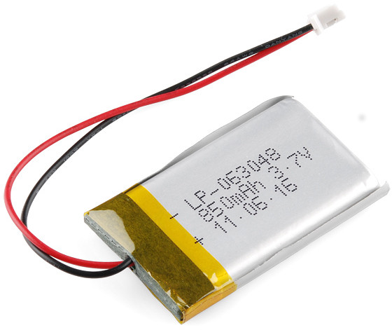
Yeah, the last but not list, as it is the battery powered device I'll be using lithium polymer(LiPo) battery, because of it's smaller and lighter form factor, and power density is quite high compared to commercially available battery technologies. The battery will be using the boost circuit as the single cell of the LiPo's rated voltage is 3.7V and I have EM18 which needs 5V for it's operation.
Circiut Daigram:
Board File
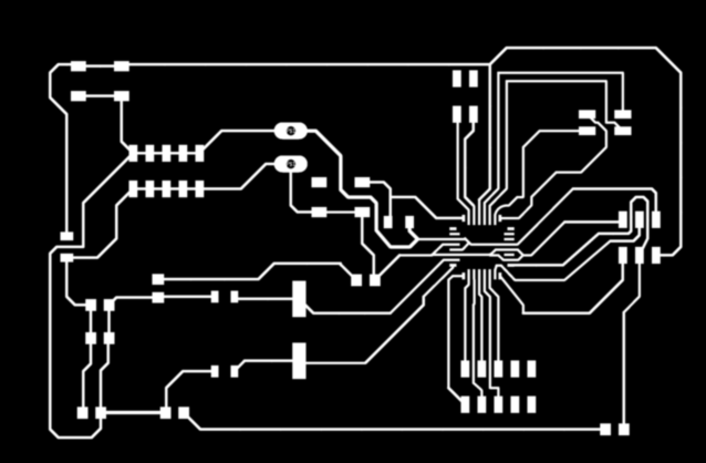
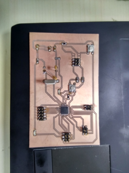
- PNG image of the board file which is will be given to the moldela for the PCB fabrication.
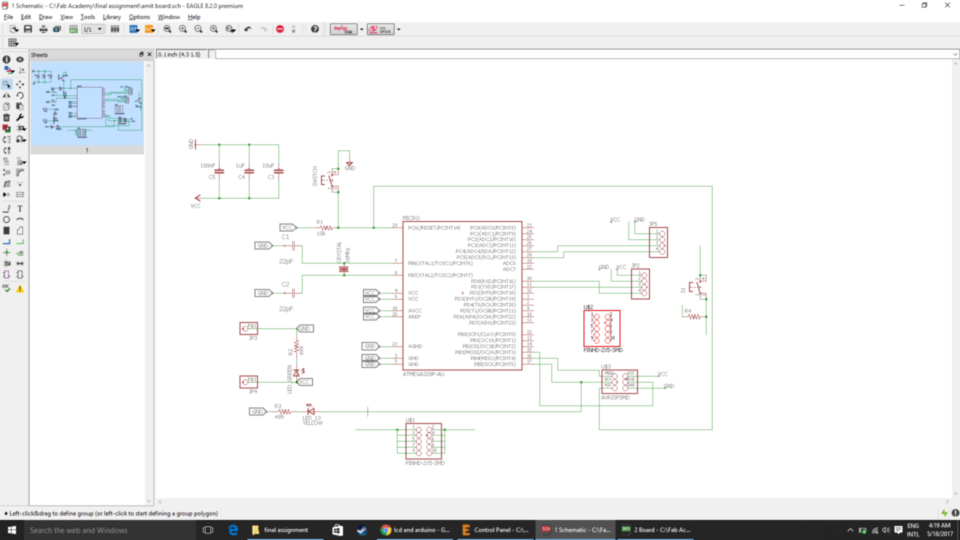
- Schematic images of the board which was made in the Eagle software.
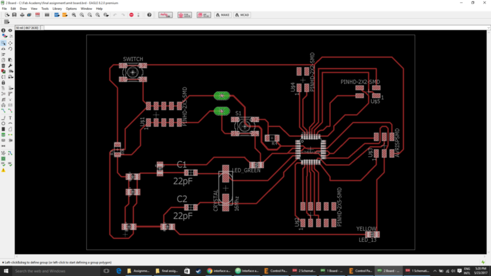
- Board images of the final PCB.
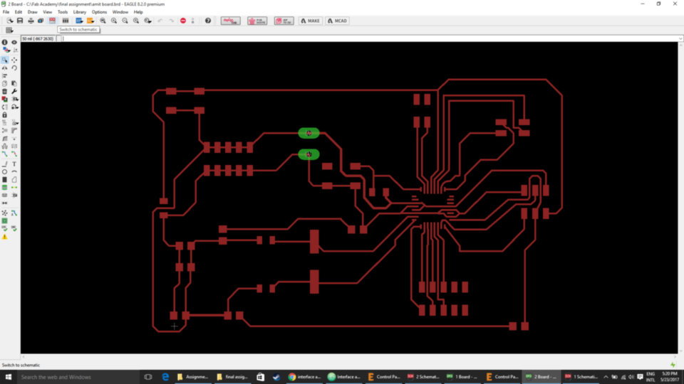
- Image of the board after milled.
Casing:
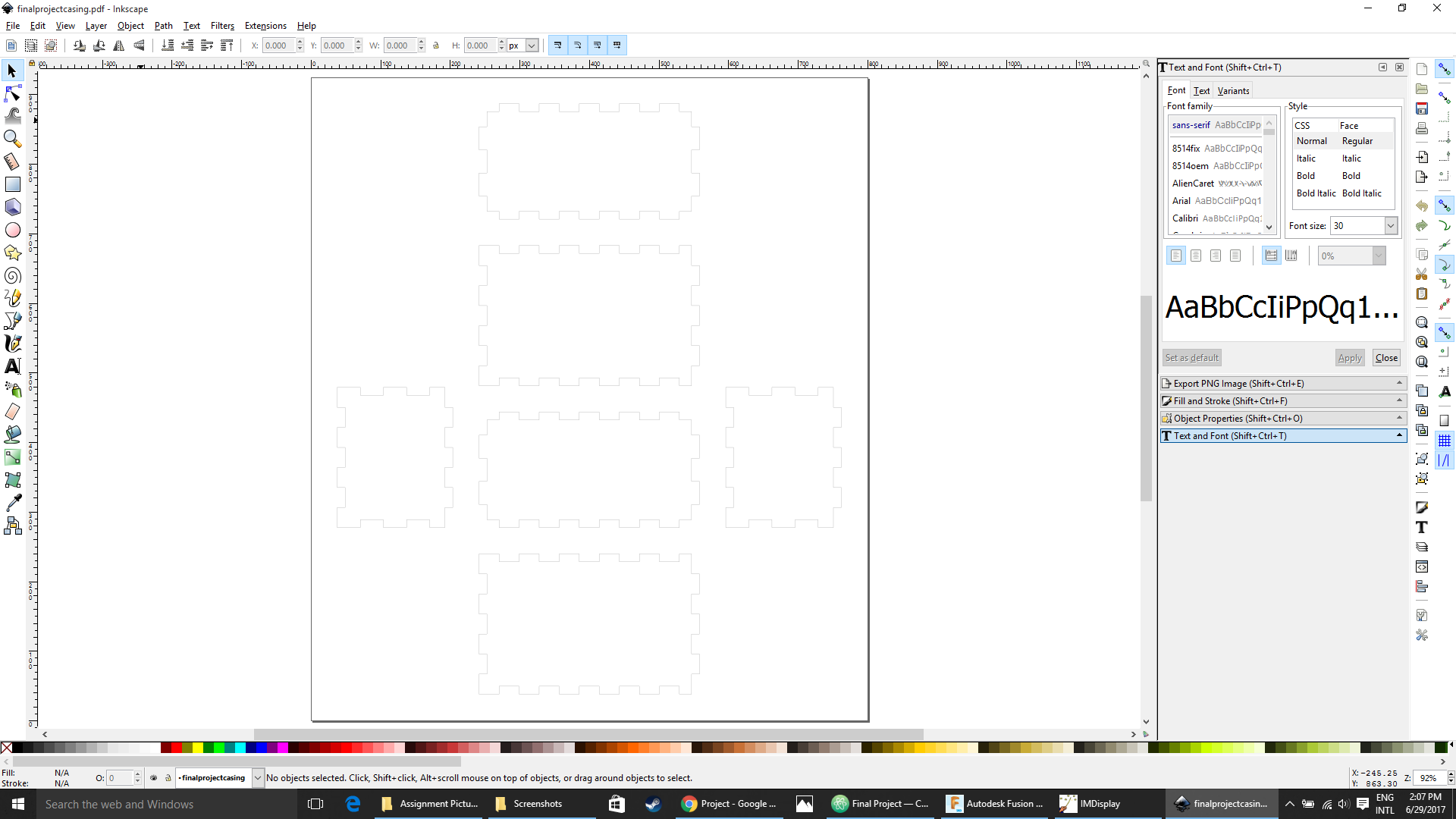
The casing is design in Inkscape. I used the plugin lasercut box which is available on the Inkscape website as an extension. You can access the lasercut box plugin from the extension tab, then click on the render option after successful installation of the plugin. When you click on the lasercut box option, a dialog box popup where you can put your values of height, weight, depth, material thickness of our kit under the dimension tab and then hit the apply button to see the results you can also see the live preview of the object by selecting on the live preview option.
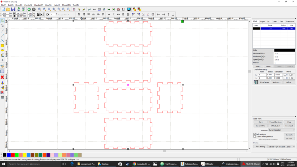
After designing the file in Inkscape, Export and/or save the design file with .dxf file which will be used in RDWork software for laser cutting the design on arcylic sheet. The Speed for laser cutting the arcylic sheet was 40mm/s and the power set was 60.
Testing & Video:
What is actually going in the circuit? How it is working?
The sensor/device used in the circuit are SIM800 which is a GSM module, MPU 6050 which is accelerometer and gyro sensor, LCD to display the data, reading from the kit and Microcontroller board(Atmega 328p) to communicate with each of the devices. When the kit is ON the SIM800 start searching for the signals, or register to some cell network to send data and/or message which is connected to the digital pin 9 and 10 on the board by using the softwareSerial command.
When the SIM800 is register to the network then the controller start reading the data for the MPU6050, which is connected to the SDA and SCL pins of the board i.e. also available at analog pin 4 and 5. The Sensing is done with the MPU 6050 which is accelro and gyro sensor.
When the value from the sensor crosses the threshold value or when it topple at a particular angle in my case it was 90 degreee and 180 degeree according to the kit placed on the cycle it sends the message "Accident occured" to the respective number stored in the device. This is the logic, since when bike falls or meet with the accident, the cycle will topple at some angle. And when the angle crosses the threshold value it which is sense by MPU 6050 it alert the system.
Connection Circuit:
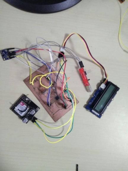
In the image below the connection is as follows:
1. SIM800 is connected to the digital pin 9 and 10 on the board.
2. MPU 6050 is connected to the SDA and SCL pins which is Analog pins 4 and 5 on the board and digital pin 2 which is used as Interrupt
3. I used Grove LCD Screen which is based on I2C communication same as MPU 6050, but they communicate on different I2C address.
4. I used USB to UART serial converter to get serial output on the serial monitor.
Testing with the SIM800
Sample code:
 #include <SoftwareSerial.h>

SoftwareSerial mySerial(9, 10);

void setup()
{
  mySerial.begin(9600);   // Setting the baud rate of GSM Module
  Serial.begin(9600);    // Setting the baud rate of Serial Monitor (Arduino)
  delay(100);
}


void loop()
{
  if (Serial.available()>0)
   switch(Serial.read())
  {
    case 's':
      SendMessage();
      break;
    case 'r':
      RecieveMessage();
      break;
  }

 if (mySerial.available()>0)
   Serial.write(mySerial.read());
}


 void SendMessage()
{
  mySerial.println("AT+CMGF=1");    //Sets the GSM Module in Text Mode
  delay(1000);  // Delay of 1000 milli seconds or 1 second
  mySerial.println("AT+CMGS=\"+91xxxxxxxxxx\"\r"); // Replace x with mobile number
  delay(1000);
  mySerial.println("I am SMS from GSM Module");// The SMS text you want to send
  delay(100);
   mySerial.println((char)26);// ASCII code of CTRL+Z
  delay(1000);
}


 void RecieveMessage()
{
  mySerial.println("AT+CNMI=2,2,0,0,0"); // AT Command to receive a live SMS
  delay(1000);
 }
Testig the MPU 6050
To test the board MPU 6050, first download the board library for MPU 6050, developed by Jeff Rowberg. You can find the library here. Next, you have to unzip/extract this library and take the folder named “MPU6050” and paste it inside the board’s “library” folder. To do this, go to the location where you have installed board (board –> libraries) and paste it inside the libraries folder. You might also have to do the same thing to install the I2Cdev library if you don’t already have it for your board. Do the same procedure as above to install it, you can find the file here: I2Cdev library.
If you have done this correctly, when you open the Arduino IDE, you can see “MPU6050” in File –> Examples. Next, open the example program from: File –> Examples –> MPU6050 –> Examples –> MPU6050_DMP6.
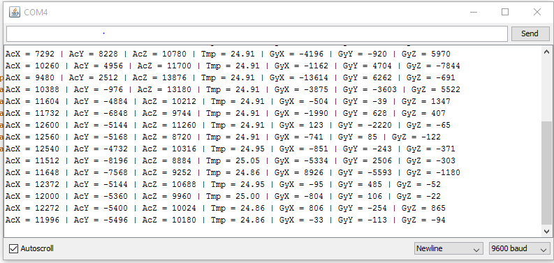
Next, you have to upload this code to your board. After uploading the code, open up the serial monitor and set the baud rate as 115200. Next, check if you see stuff like “Initializing I2C devices…” on the serial monitor. If you don’t, just press the reset button. Now, you’ll see a line saying “Send any character to begin DMP programming and demo.” Just type in any character on the serial monitor and send it and you should start seeing the yaw, pitch, and roll values coming in from the MPU 6050. Like so:
Output Values from MPU 6050
BOM
Electronics Materials
Hardware Materials
• Acrylic Sheet of 300mm x 600mm size 3mm in thickness - 5 Nos. (Lab)
Cable ties
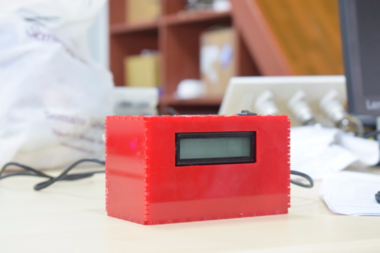
Hero Shot
Project Video :
DOWNLOAD DESIGN FILES

This work is licensed under a Creative Commons Attribution-NonCommercial 4.0 International License.