Goal of the Assignment
This assignment is focused on the converting the CAD drawing into the real-life objects. Computer numerical control (CNC) is the automation of machine tools by means of computers executing pre-programmed sequences of machine control commands. This is in contrast to machines that are manually controlled by hand wheels or levers, or mechanically automated by cams alone.
In this assignment it's time to make something big which can be used by me and others in my day to day activities. I was thinking about the things that I simply make which can be used in my lab. I was thinking to make a chair or stool to sit on it.
he goal of this week's assignment will be making a stool, and machining it using the Wood CNC Router machine.
Lets get started with the assignment.
Designing
I've started thought process with the laptop table in mind. I started with measuring the dimensions of my stool which turned out to be 460x460x460 mm.
I decided to use the 12mm thick plywood which is quite enough to take the weight of person.
Designing in Solidworks:
Solidwork is a nice software which allows us to generate renders as well as it allows to make the assembly of the parts designed. Assembling of parts helps me to understand what can go wrong while making it into real world. And if any corrections required that can be done right on the software at the time of assembly.
I. Making the Seat
1.Using line command or rectangle command and construct a square of 460mm X 460mm X 460mm.
2. Fillet all your corners with a radius of 100mm
3. From the center of the fillet arc draw a line and sketch 2 slots of dimension 34.34mm X 12mm and one slot of dimension 100mmX12mm on both sides of the central line( Mirror entity tool can be used for ease of sketching)
4. Using the extrude boss base tool to extrude the sketch. Extrusion length 12mm.
Making the Legs
Using the line command draw a horizontal line of 90mm then a vertical line of 12mm then a horizontal line of 34.34mm now drop a vertical of 12mm, Repeat this step for the second slot and Make the central slot with a dimension of 100mm X 12mm.
Sketch two vertical lines of 460mm length and make two slits of 10mm thickness and 155mm depth. Using extrude boss base tool, Extrude the leg with 10mm extrusion.
For the next leg Sketch a line of 374.14mm and drop two verticals of 460mm.
Make two slit of 10mm thickness and length 305mm. Using extrude boss base tool, Extrude the leg with 10mm extrusion.
Making the assembly
After designing and extruding all your parts. Open solidworks and open a new assembly file.
Assemble all the parts mate them properly using the mate tool. You can use parallel and co-incident mating.
After it is ready you can choose the material from the Material menu and choose the wood.


Exporting files - DXF format
Here for the designing purpose I've used the SolidWorks with make the 3D model. It's time to make it 2D which can be used by most of the machine softwares. Also, when you have DXF files which can be opened in the software for further modifications if required.
Generating tool-path using ARTCAM
Tool path generation is the major task in the computer aided machining. Tool-path is nothing but as name suggests, it tells the machine how tool should move to do the job perfectly. As my Instructor Akshay Goharkar always says "Tools don't have brain use your own", that I realized here. So, for every part in our design we have to mention
what the tool should do? How much time it should pass to cut the object without breaking tool? What is the tool size? What is 2D profile and what is and what is pocket? Observer the pictures attached below
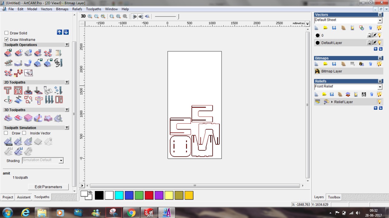
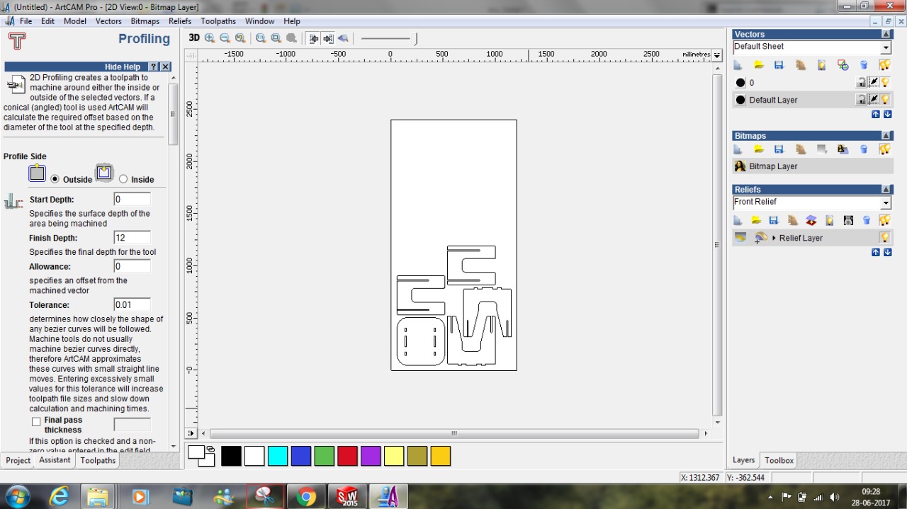
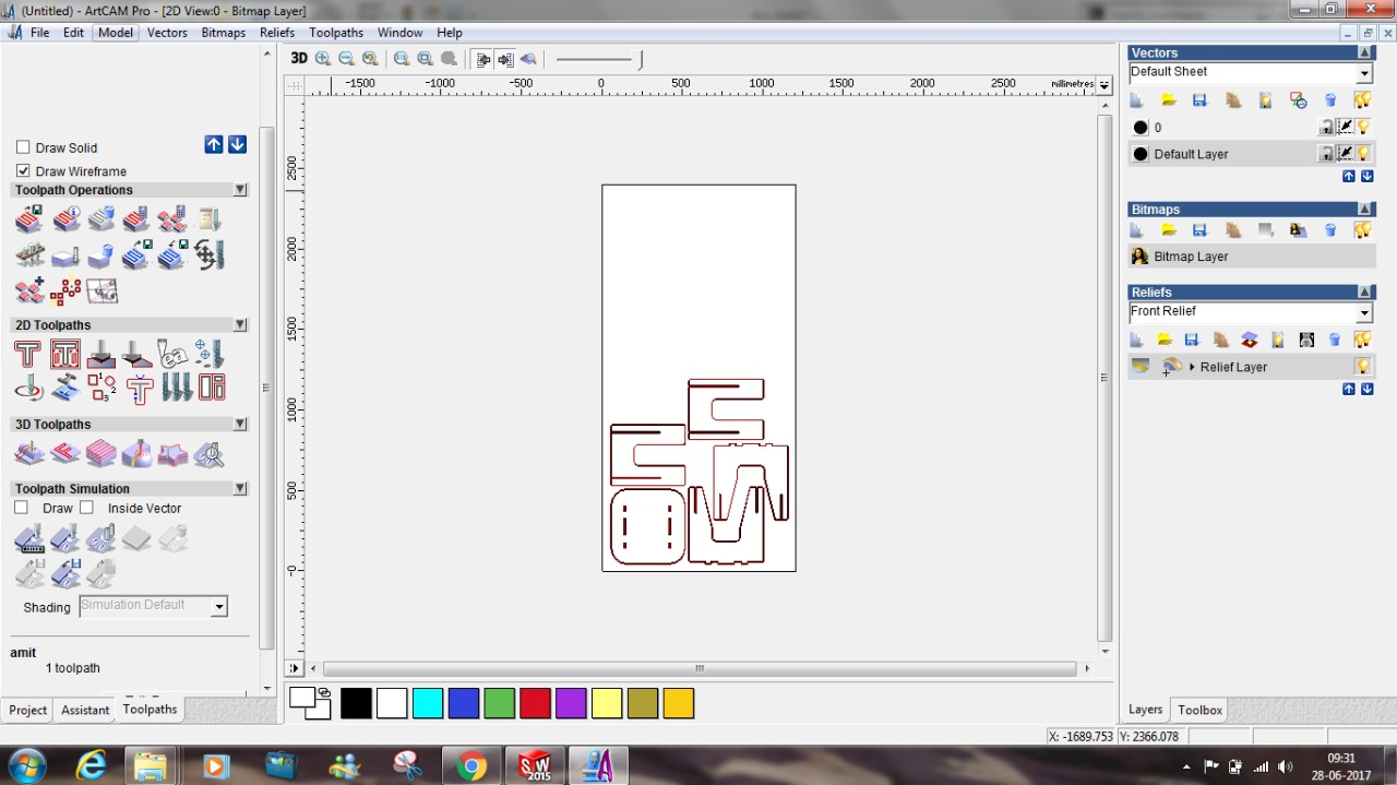
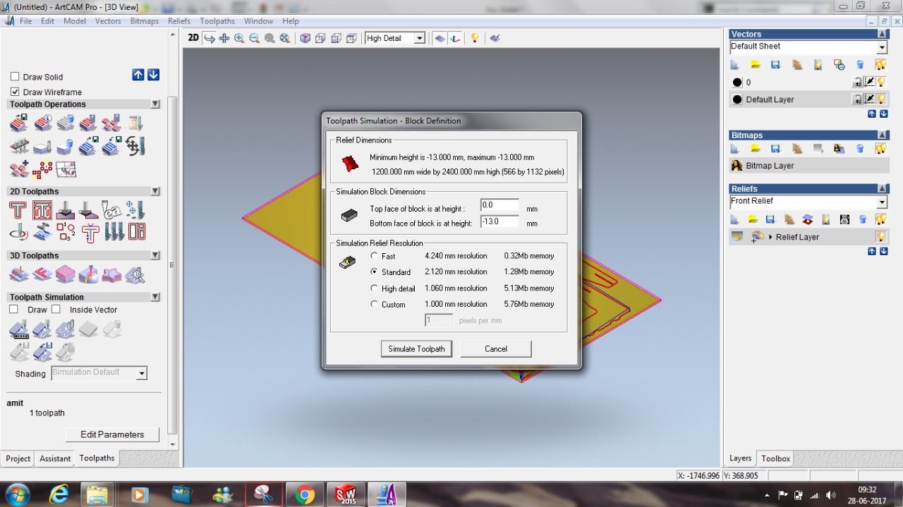
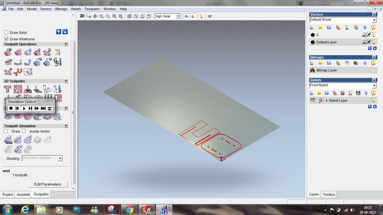
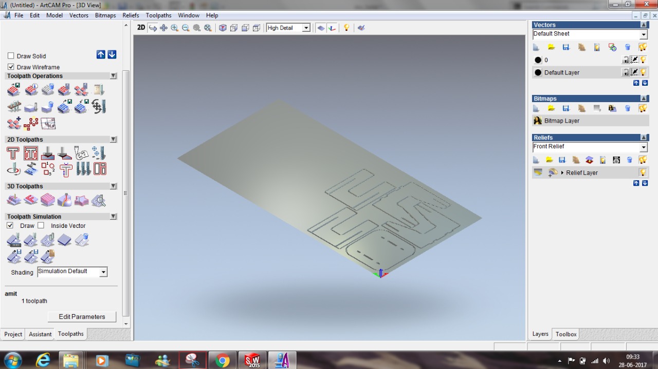
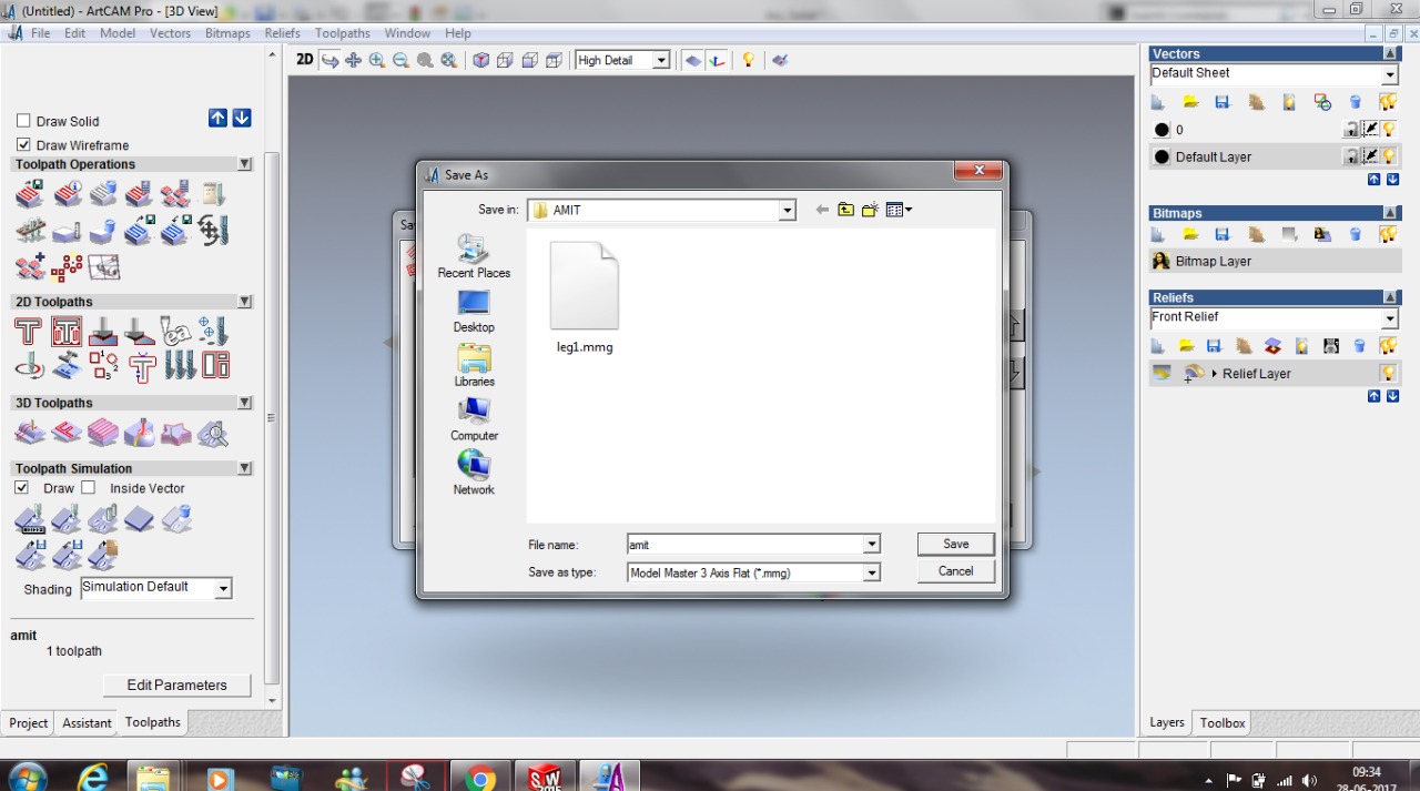
You can see two different views there in the screen-shots. One shows the 2D design and one 3D. The 2D view shows the line drawing where I selected the different paths and contours to be as pocket and to have 2D profile.
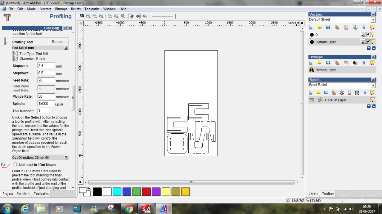
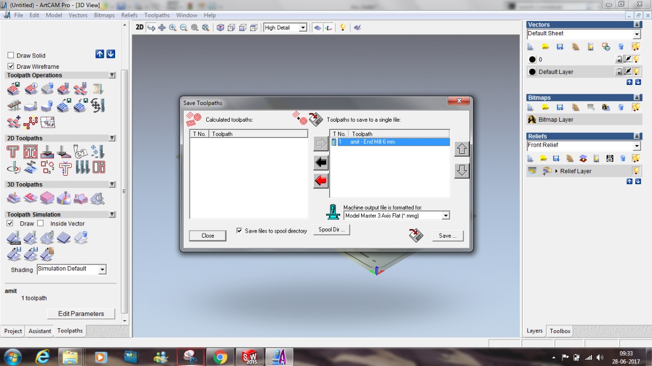
Pocket => Engraving 2D profile => Cutting Once we are done with the tool-path and tool-selection it's time to export shopbot file which has extension .mmg. This file we can import in shopbot software with which we can machine the material loaded.
I was using the 6mm end mill bit for cutting, Cutted 12mm plywood in 4 steps with the feed rate of 50mm/1sec and pluge rate of 25mm/sec rpm is 12000/sec
How to change tool?
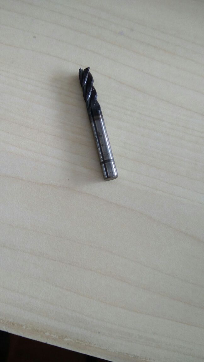
- Access the tool rack and get the appropriate tool
- Get the tool changing spanner
- Loose the tool holder by rotating both the spanners in inward direction and remove the tool
- Load the appropriate tool, use spanners to tight but this time move them outward to tight it

Adjusting Z zero
Zeroing Z is very important activity that one should do. Doing this make the machine aware that what's the position of the tool with respect to material thickness and how much depth it has to reach for cutting/engraving. When you give command for zeroing the Z with the controller the z start going downward and as soon as it touches the surface we make it zero with the help of controller, after this machine remember the position and goes up 1 inch and stays there.

Controller command


Final Results:


DOWNLOAD DESIGN FILES
References
- ShopBot
- What is CNC?
- Eat your meal sitting on the floor
- 10 reasons why you should eat while sitting on the floor