Electronics Design
In this assignment we have to remake the echo hello world circuit by adding the led and a push button to it.
For this I have used Autodesk Eagle. For making the schematic of the pcb and the board file.
I found Eagle easy to understand as it allows to make a schematic diagram which is simple to understand. So I decided to continue my electronics design with eagle. Because it was taught by my professors in first year of Engineering.
Steps for creating our own hello world circuit is as follows:
1. Eagle Software for designing of hello world circuit.

2. Then I used the ADD command to add the components to the design layout which is available under the command button
bar.
.png "PNG FILE")
3. I added the ATTiny44 chip from the ADD Command option.
.png "PNG FILE")
4. In the similar fashion i added all the components such as resistor, capacitor, Leds, button, AVRISP SMD header pins,
etc.
.png "PNG FILE")
5. I used the command net to join the two components pins with each other.
.png "PNG FILE")
6. After connecting all the component with each other, to know wether all the components are connected or not with the
ERC command.
.png "PNG FILE")
7. Since there are no error from the ERC error dailaog box we are ready to switch from the schematic file to board file.
.png "PNG FILE")
8. In the Board version, after arranging the components in the proper place, then route the wire with the routing option available from the command button bar.
.png "PNG FILE")
9. Before using the route option, select the ratsnet to so that the number of wires should be reduced.
.png "PNG FILE")
10. Then use the route option to make respective connections.
.png "PNG FILE")
11. DRC Parameter
Clearance Tab: all settings. This determines clearance between different types of object. Normally set all equal. Just because a fab house can handle down to 5mil traces and 6mil space doesn’t mean you should design with those sizes. If your board can be routed with 10mil traces and 10mil spaces, do it!
.png "PNG FILE")
Sizes Tab: minimum width setting. This defines minimum track width. Normally set equal to clearance.
.png "PNG FILE")
.png "PNG FILE")
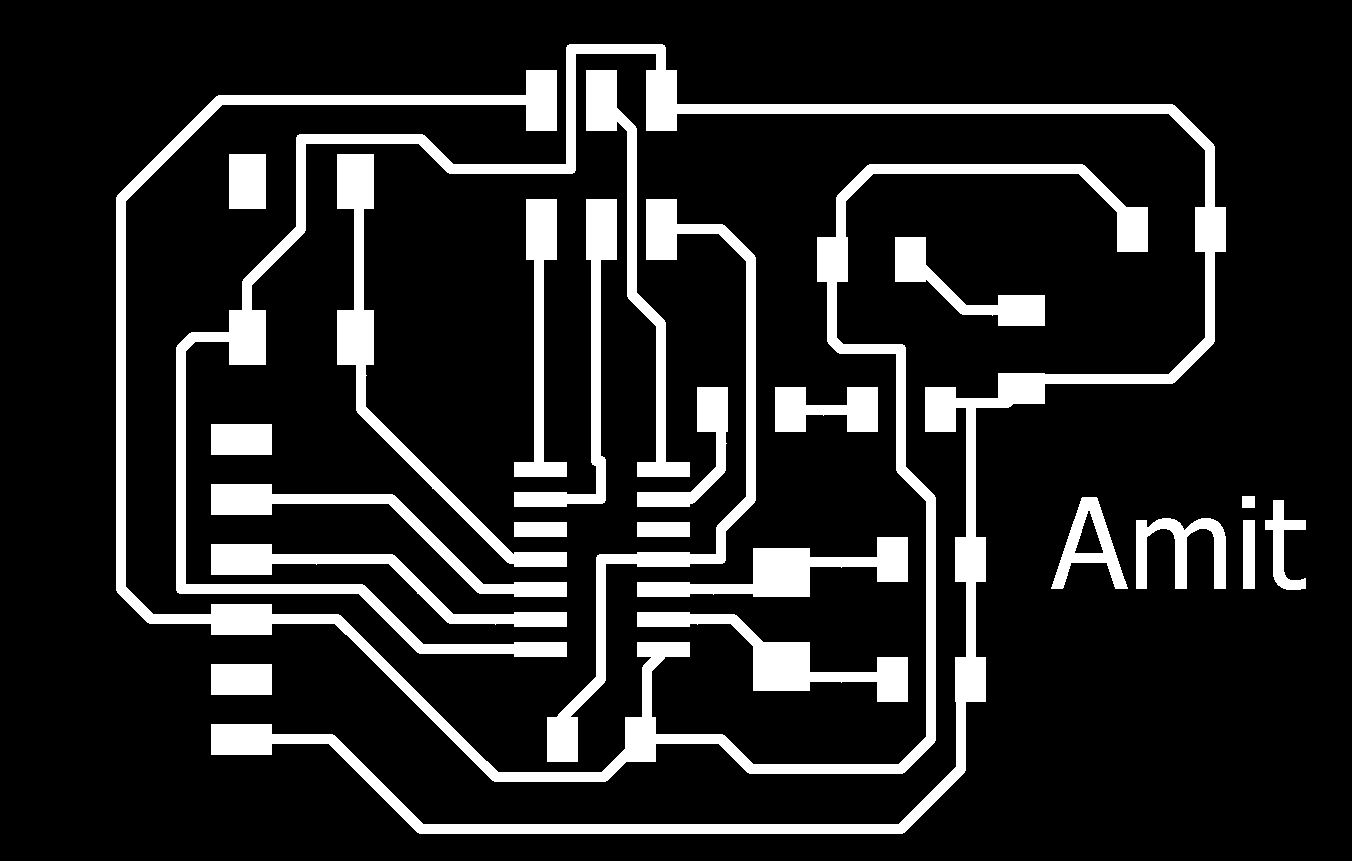
12. Then export the file for fabrication. Save it in .png format 600dpi monochrome.
.png "PNG FILE")
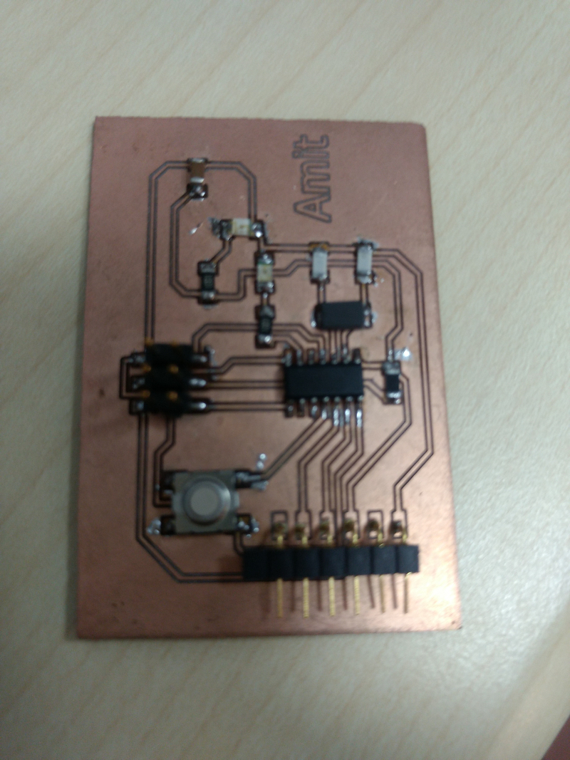
PNG File of hello world is ready to be milled.
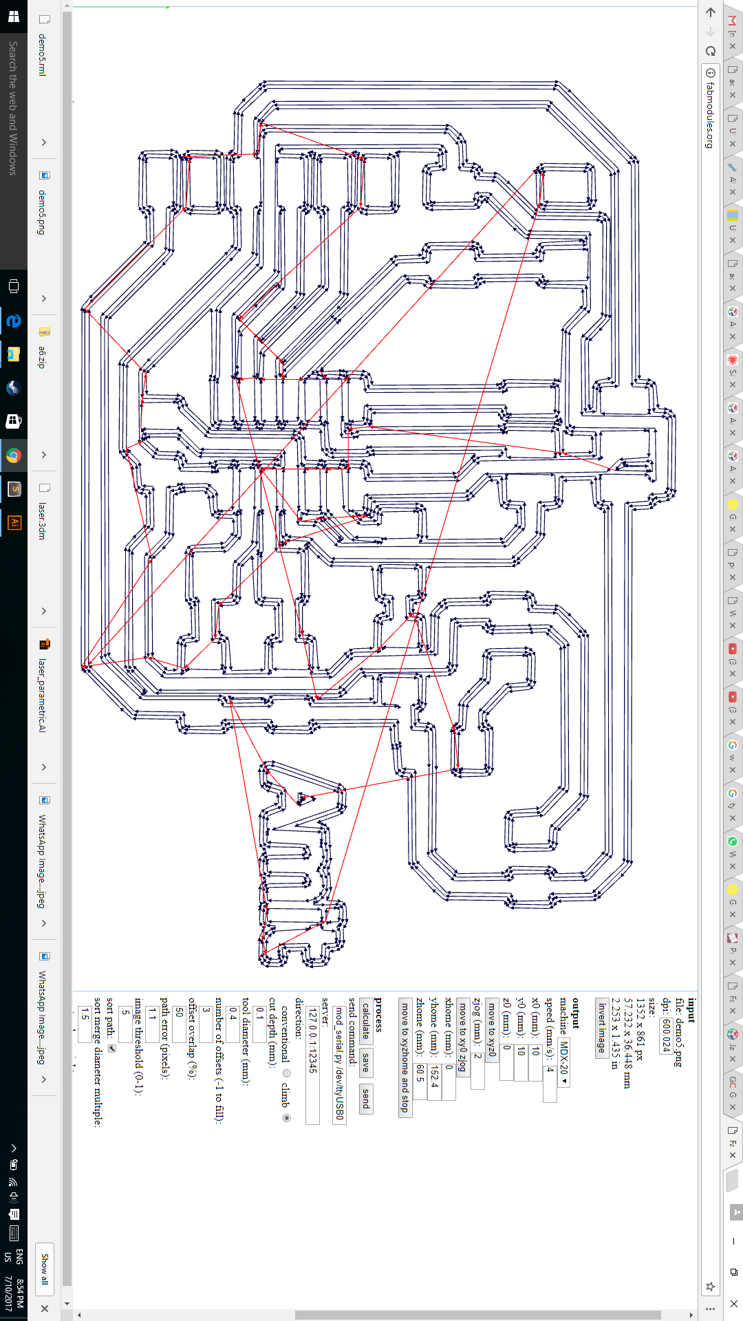
Fab Modules
Fab Modlues help me know weather which tracks are joint and which are clear and can be milled. This trail and error help me to make a proper PCB so that I make a single shot pcb a one go.
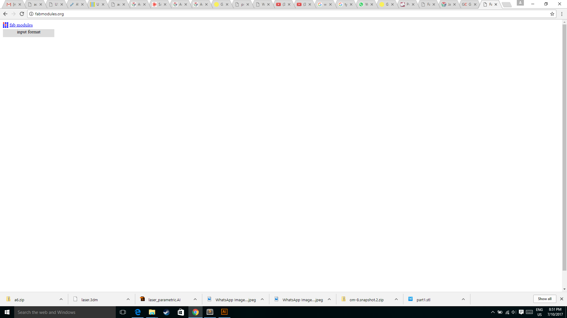
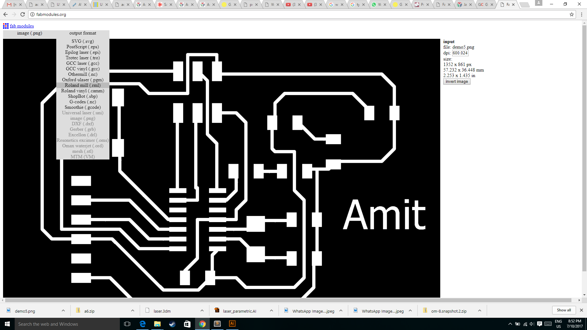
Then I imported the png file whioch is to be milled.
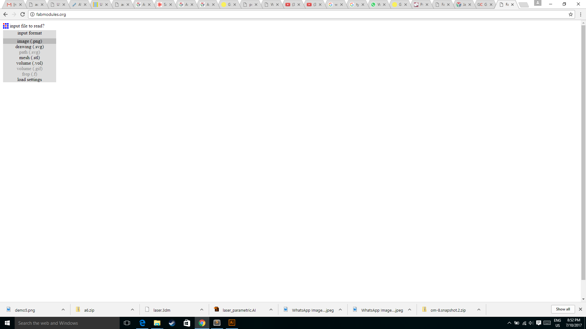
Then I selected the output format which is the Roland mill
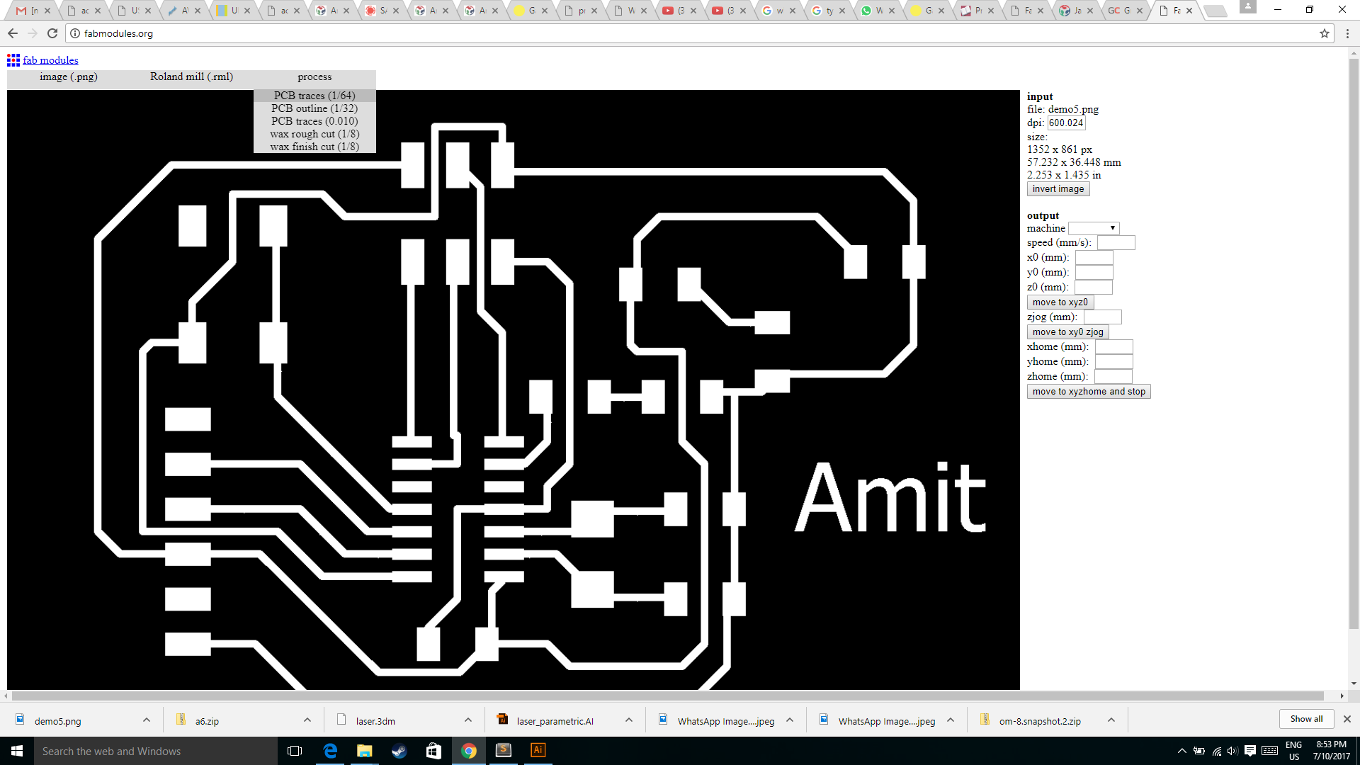
For milling I selected the 1/32 process to mill the traces.
Then on the right hand side there is option for the output machine in which I selected the MDX20 because I have that machine available.
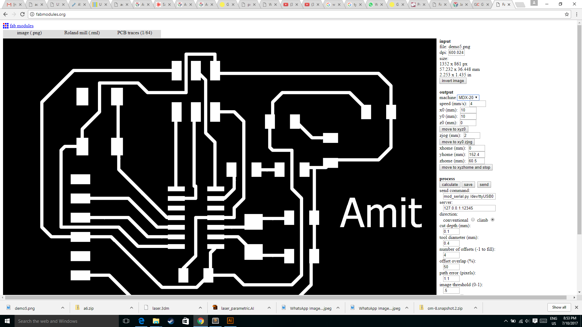
Then I clicked on the calculate button to calculate the trace, and check whether the trace are joining with each other.
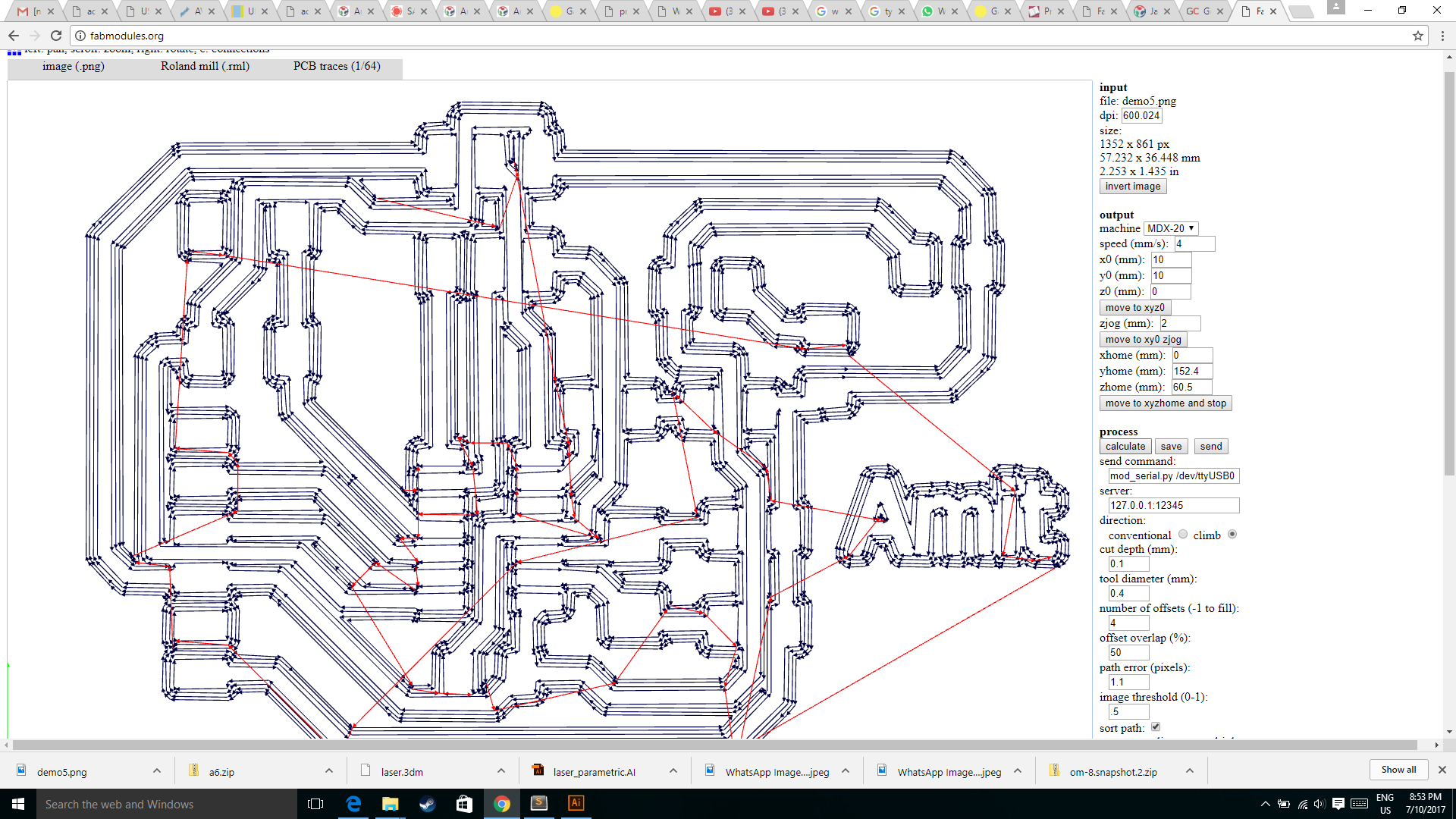
Then I clicked on the save button to generate the rml file which you can see at the bottom of the image.
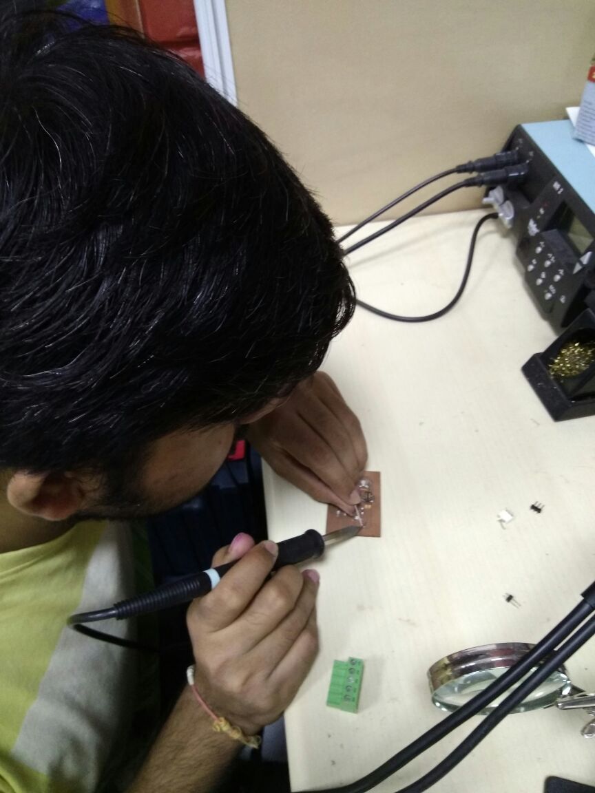
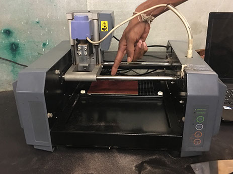
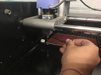
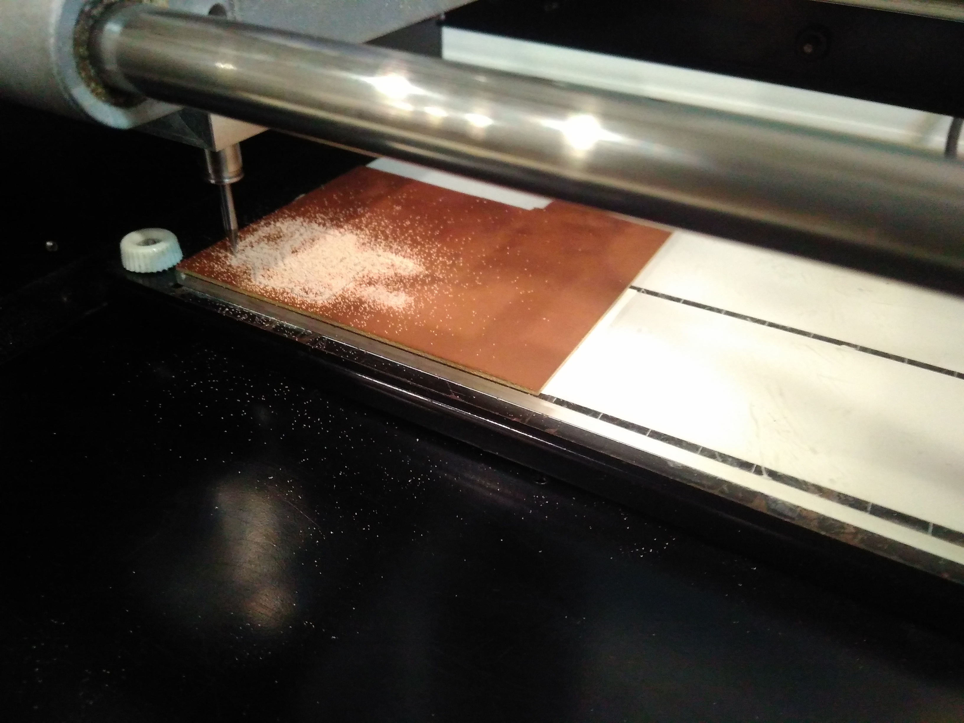
Milling the pcb on the Modela machine
After adjusting the millng parameter
Adjusting the end-mill: end mill is supposed to be adjust exactly touching the PCB surface not piercing the PCB as shown in the figure.
1. Insert a cutting tool in a collet.
Do not insert to the portion of an edge. When you use included cutting tool,
refer to the following figure.
2. Tighten the set screw with hexagonal wrench.
3. Click [View] of VPanel.
A spindle head moves to a center and a table moves to the front.
4. Loosely tighten the collet with cutting tool.
Insert the collet, and then loosely tighten.
5. Fully tighten the collet.
Tightly secure the collet by using two spanners.
Process
Components needed for the board:
| 1 ATTiny 44 microcontroller | 1 Capacitor 1uF |
| 2 Capacitor 10 pF | 2 Resistor 10k ohm |
| 3 Capacitor 10 pF | 1 Resistor 100K ohm |
| 1 Resistor 10K | R2 100ohm |
| 1 USB connector | LED 1 |
| 1 Cystal 20MHz | LED 2 |
| one usb mini cable | one ribbon cable |
| two 6 pin connectors | R3 100ohm |
| Jumpers J1FTDI | Jumpers J2FTDI |
Populating the baord