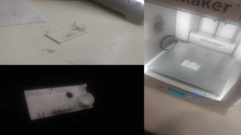
GOAL OF THE ASSIGNMENT
This assignment is focusing on 3D Printing and Scanning. In this assignment we have to Scan and Print an object.
The assignment consist of group project and single project which is basically for 3D printing and Scanning of the object.
3D Scanning
What is 3D Scanning?
For 3D Scanning we require a sensor called scanner which can scan an object. There are various sensors available in the market, for the scanning such as
- Kinect
- iSense
- 3D Sense
For My project I used Kinect XBOX 360 sensor as 3D scanner.
What is Kinect?
--> Kinect (codenamed Project Natal during development) is a line of motion sensing input devices by Microsoft for Xbox 360 and Xbox One video game consoles and Windows PCs. Based around a webcam-style add-on peripheral, it enables users to control and interact with their console/computer without the need for a game controller, through a natural user interface using gestures and spoken commands
Below is the image of the Kinect:
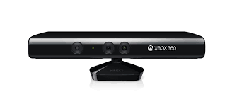
If you are newbie, installation Kinect driver without the proper flow will be a tedious job.
This is the video link for the Kinect installation.
When you first connect the Kinect to your PC you will come along to counter with a problem with Xbox NUI Motor. This means we need to install the drivers for the same.
*Note: If you are using windows 7 the kinect will not work, because it's SDK requires Windows 8 or higher version OS of Windows.
These are the links of the Software to be download for the kinect to use as 3D Scanner.
After Successful Installation of the drivers to know the Kinect is ready to scan the object/material. Go to the C:\Program Files (x86)\OpenNI2\Samples\Bin and open SimpleViewer.exe.
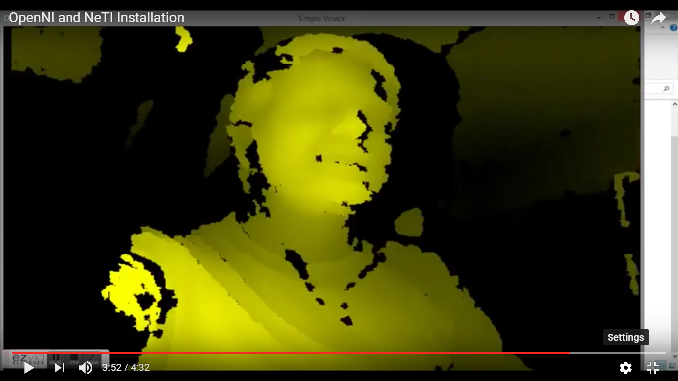
Now we are good to go--------->
For 3D Scanning software I have chosen Skanect. Below the attached image of its
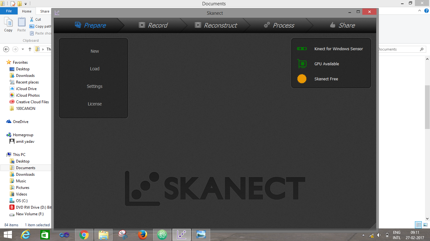
Setting up the software:
Open Skanect / Go to NEW / Make sure your settings match those in the picture
Press START
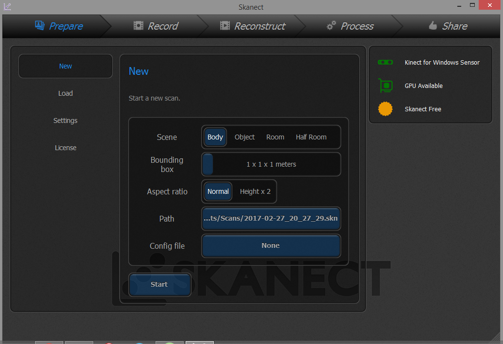
Workspace area
A screen will come up showing the bounding box in the middle. The infrared and video images and also depth information are on the right side of the screen. In the middle is a preview of the scan.
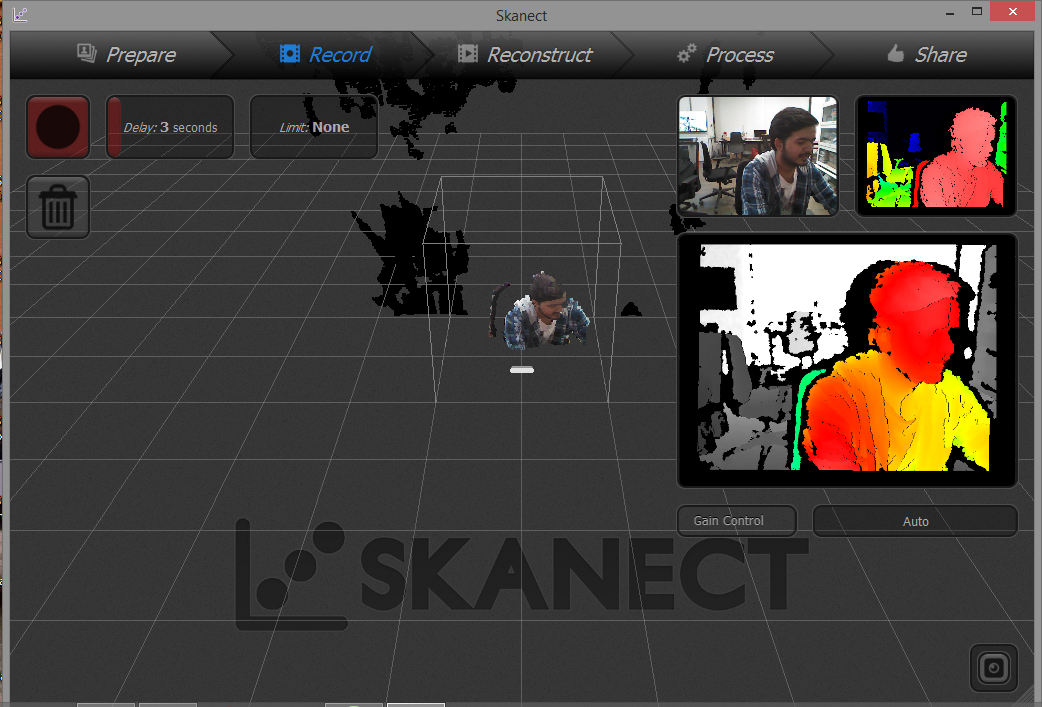
Record
Now hit the record button
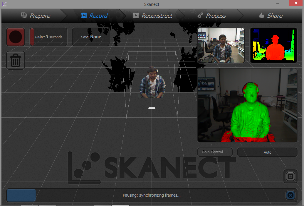
while scanning be sure that you are getting a high frame rate around 18-24 frames. If you get below 18 you have to move your Kinect faster.
Record output:
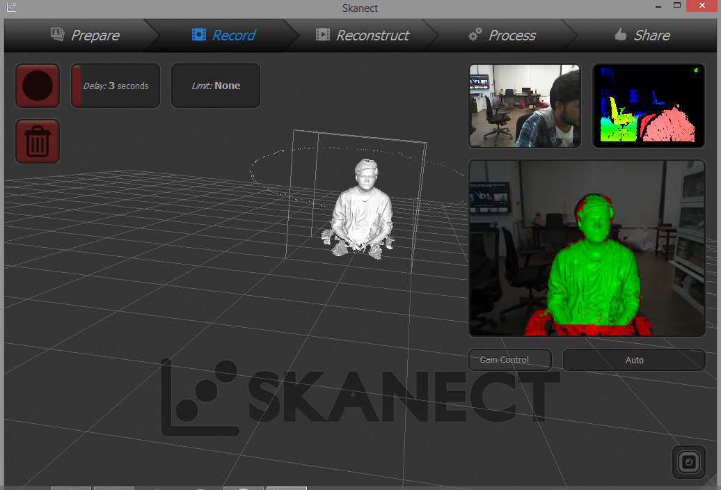
Cleaning up your scan
Now proceed to the Process tab to edit/refine your model.
Here is where you can modify the mesh and add the color to the model. Click on 'Simplify', and 'Fill holes' and apply watertight and smoothing medium to the model. This will start the post-processing, closing all the holes and making the mesh water tight, removing any bad scan data, and adding the color to the model by colorize.
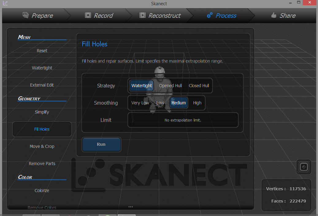
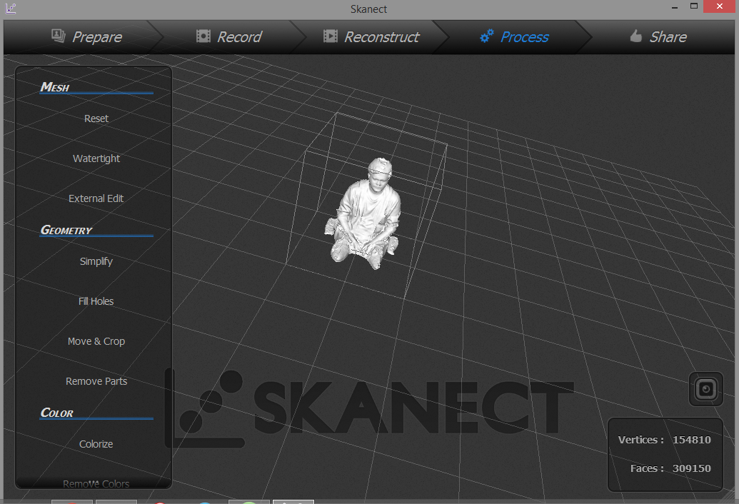
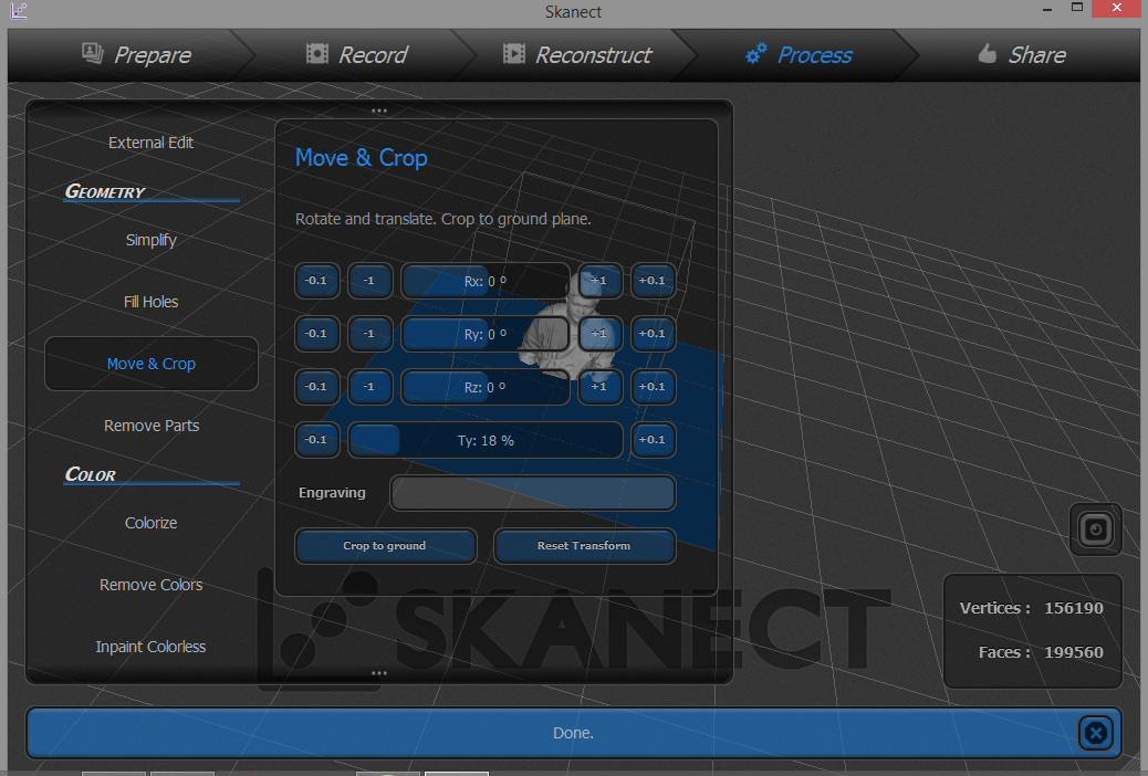
Now we have to use the MOVE & CROP tools. Use the SLIDE BARS to adjust the X, Y, and Z axis of your scan to make it flat and straight.
Exporting Model
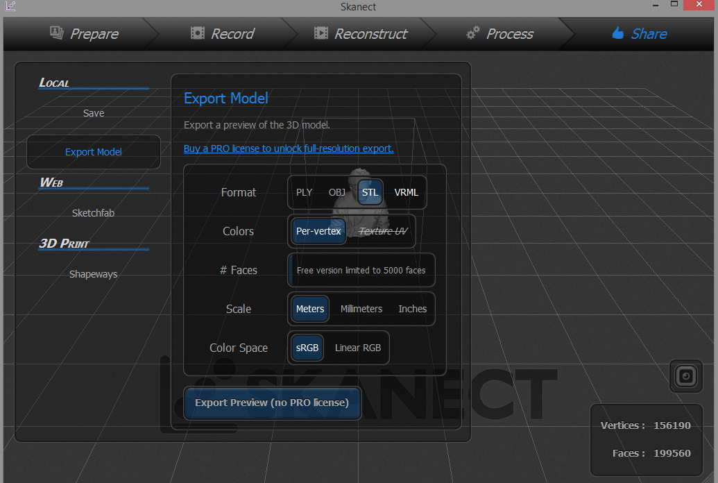
The final step is to move to the Share tab to save
and/or export your model.
The Save function allows us to reopen our project in Skanect later for futher editing.
The Export function allows us to save our model out for 3D printing and that we need to save in .STL format
Final Output:
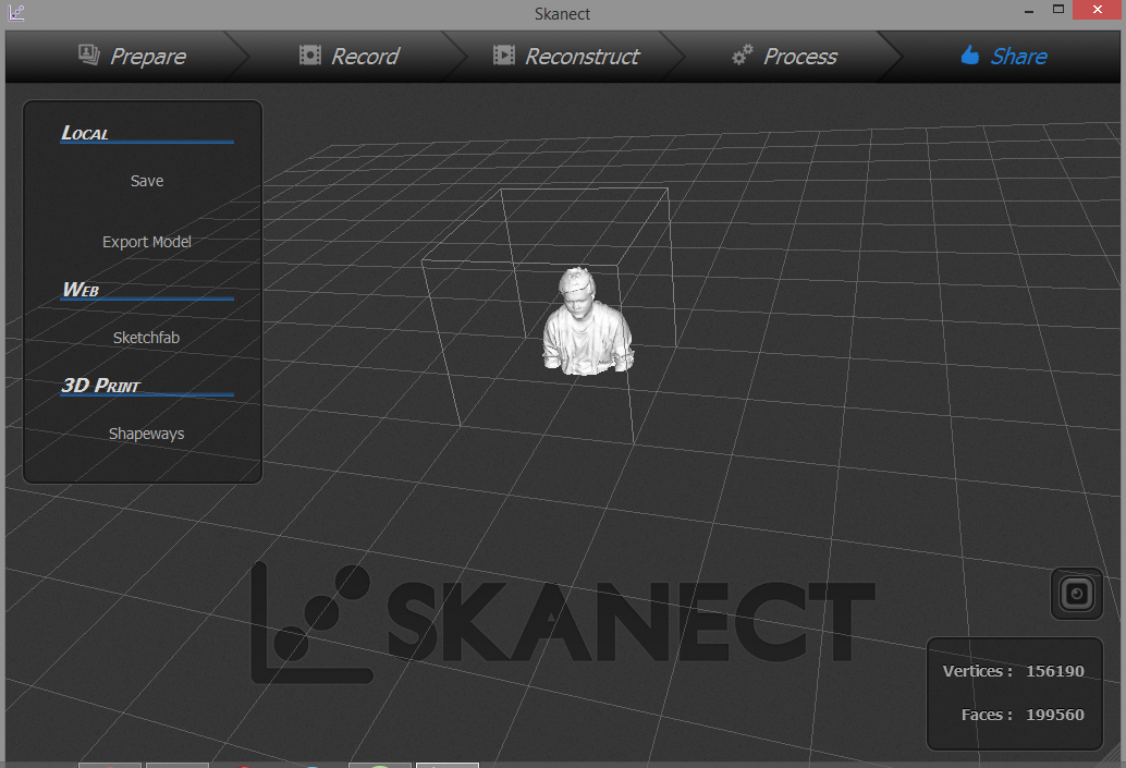
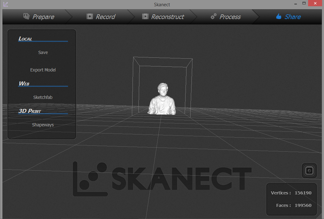
Video setup for 3D Scanning
Now It's time for second part : 3D Printing.
What is 3D Printing?
--> Wikipedia: 3D printing, also known as additive manufacturing (AM), refers to processes used to synthesize a three-dimensional object[1] in which successive layers of material are formed under computer control to create an object.[2] Objects can be of almost any shape or geometry and are produced using digital model data from a 3D model or another electronic data source such as an Additive Manufacturing File (AMF) file.
What is Additive Manufacturing?
Additive Manufacturing is actually a synonym for 3D printing and/or any process by which 3D objects are constructed by successively depositing material in layers such that it becomes a predesigned shape. Modern 3D printing has always been very useful for rapid prototype development but it is starting to make its impact on the manufacturing world as well. Read here for five ways additive manufacturing made its mark as a manufacturing tool in 2015.
What is Subtractive Manufacturing?
Subtractive manufacturing is a process by which 3D objects are constructed by successively cutting material away from a solid block of material. Subtractive manufacturing can be done by manually cutting the material but is most typically done with a CNC Machine. Advanced CNC machines utilize multiple tools and cut around at least three (x, y, and z) axes such that they minimize the requirement for designers to flip the block. One of the principal advantages to subtractive manufacturing is the ability to machine an extremely thin piece of plastic into a living hinge. This kind of process is simply not yet possible in a 3D printer. For those prototypes that require living hinge components it is useful to produce certain parts using additive manufacturing while using the CNC machine for specialty components like a living hinge.
In this assignment we need to design and print a 3D object (small, few cm) that could not be made subtractively.
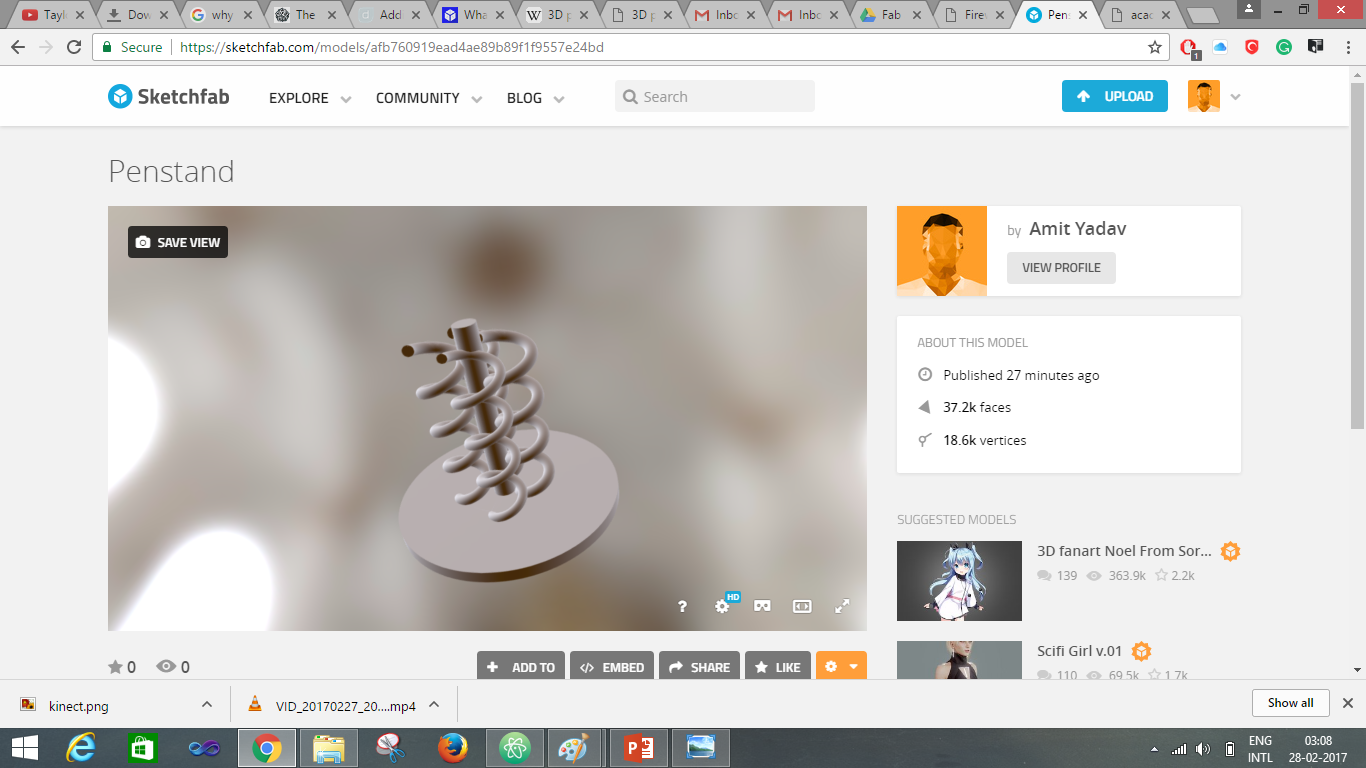
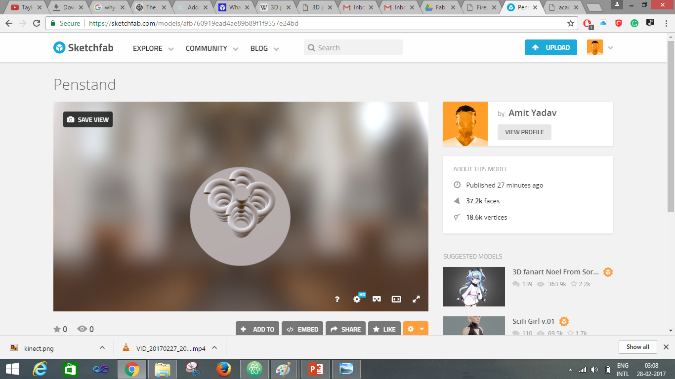
So for this I had made a Pen and Pencil Holder with a different holding bracket.
For that is have used Autodesk Fusion 360.
Below are the images of how I sketch the object.
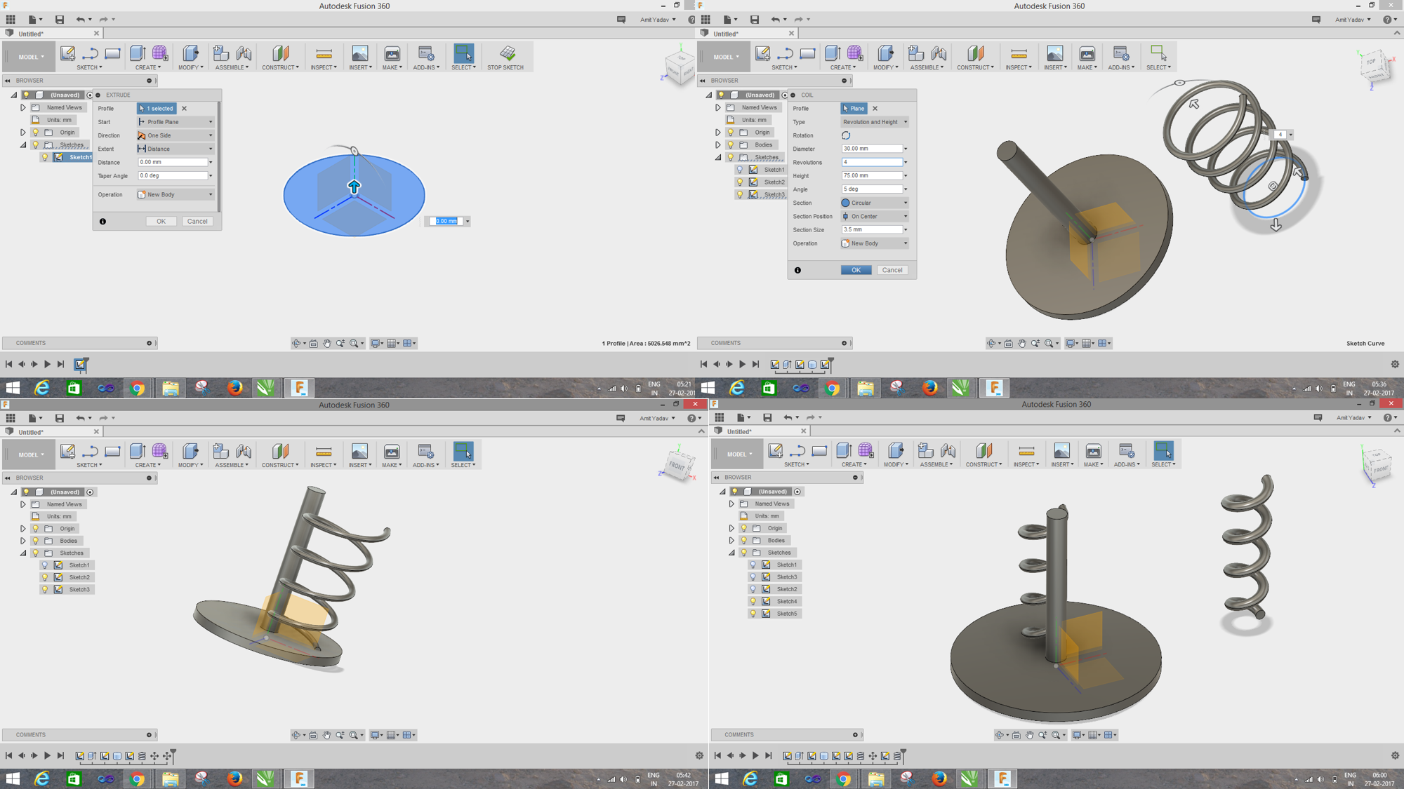
Here is the final model of the object
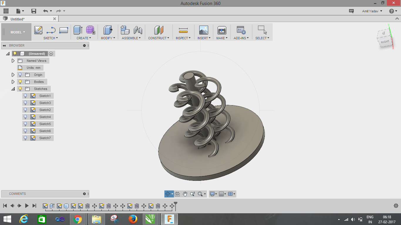
After rendering:
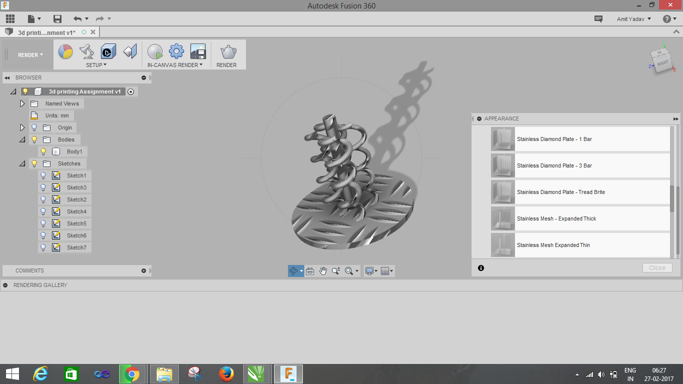
CAD MODEL
Let's begin with the Printing process!!!
For the printing I am using Ultimaker 2 and PLA for 3D printing. So I imported the .STL file of my object to Cura Software. Cura 3D is slicing software for 3D printers, it takes a 3D model and slices it into layers to create a file known as G-Code, this is the code that the a 3D printer understands.
I imported the file in the machine software for Ultimaker 2, which is CURA. There are tools available to set the object properly on the printing bed. Proper alignment of the object is necessary if not done properly the object may not be printed properly or may be extra support material will be printed. So to avoid these errors the software provides a tab to Lay Flat the object on the print bed.
After aligning the object properly now I set the parameter to print the object, which is as follows:
Quality
Layer height : 0.1 mm
Shell thickness :0.8mm
Fill
Bottom/top thickness : 0.8mm
Fill density : 20%
Speed
Print speed : 60 mm/s
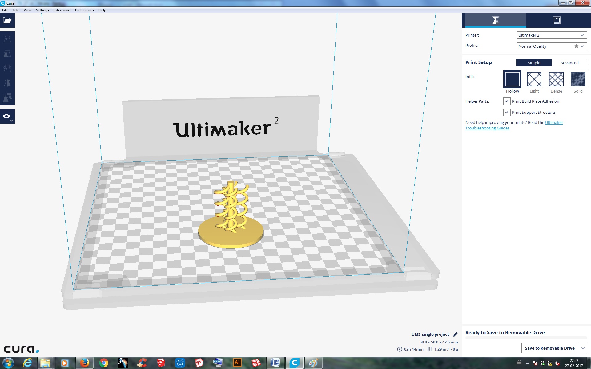
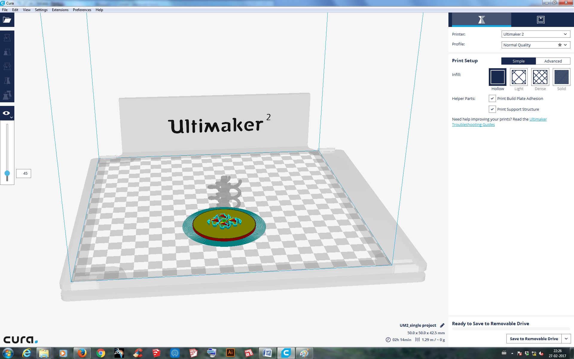
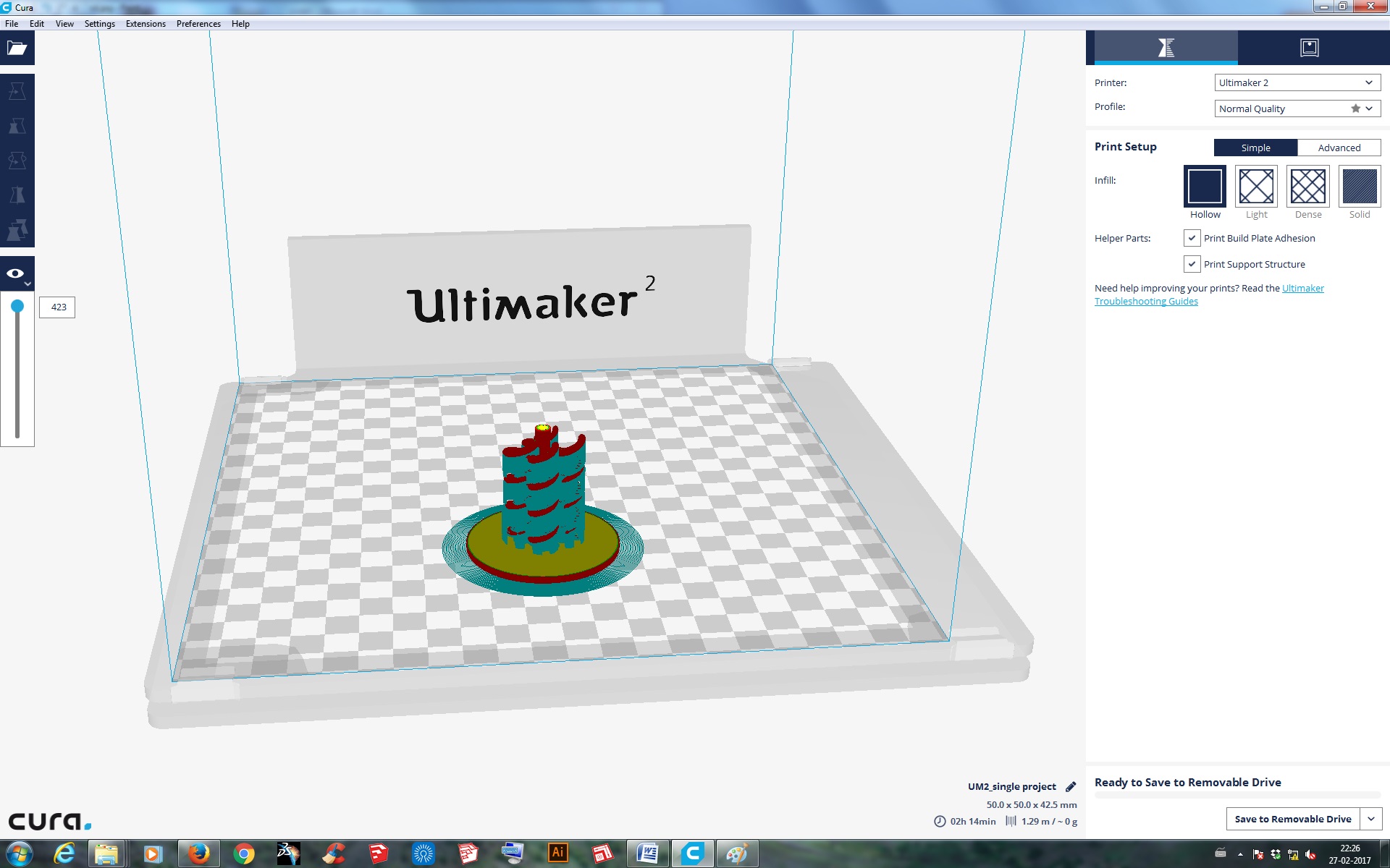
3D Printing Processing stages:
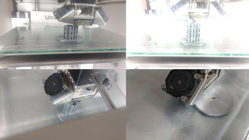
Final Output:
Post processing ->
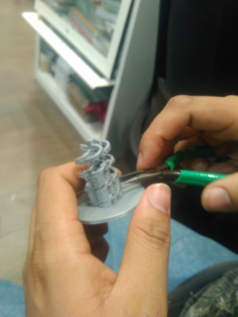
My Observations :
1. I selected Ultimaker 2 for my 3D printing becuase the printing qulaity is good.
2. Time take by the 3D printing is 2 hours.
3. The material used is PLA.
Output->
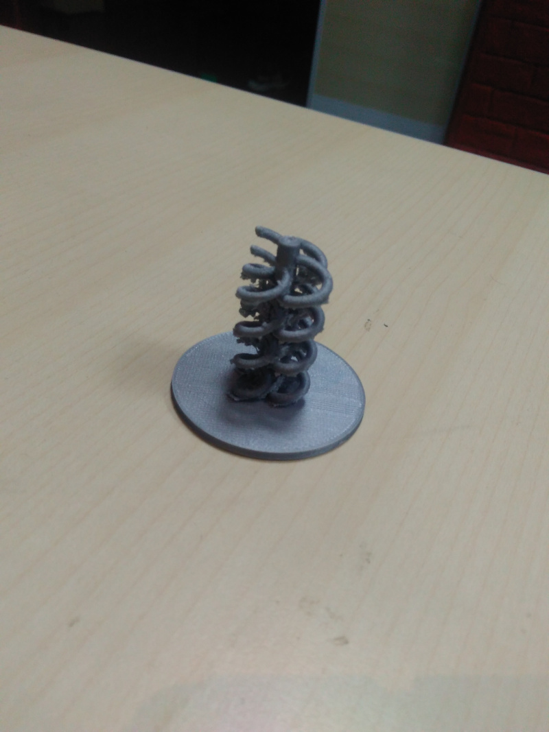
Now the Third Task: TEST THE DESIGN RULES FOR YOUR PRINTER(S) (GROUP PROJECT)
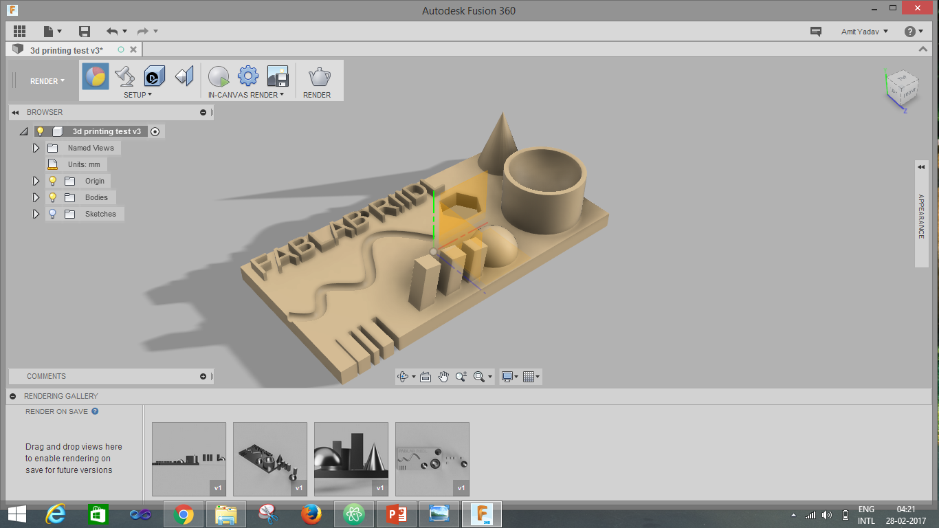
For the group project we decided to make different cutout shapes, extrude, hollow, sharp things to know how 3D printer performed.
Sketch is shown in the below image.
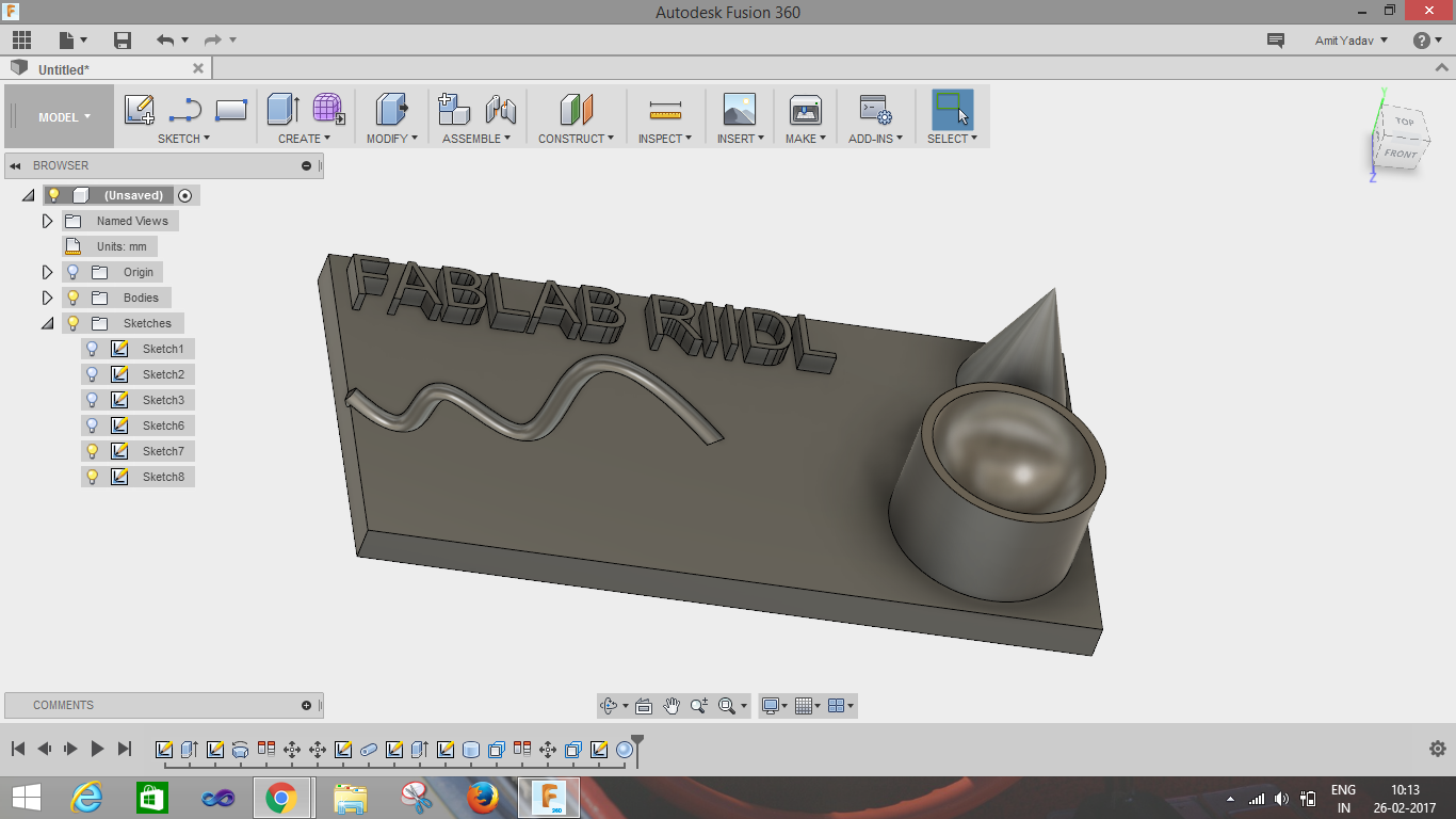
Images shown below describe how the sketch is constructed.
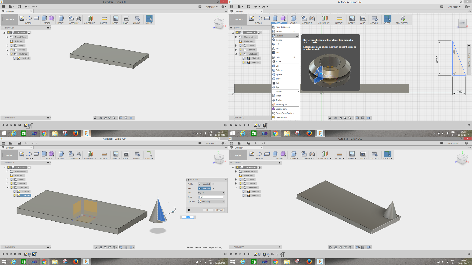
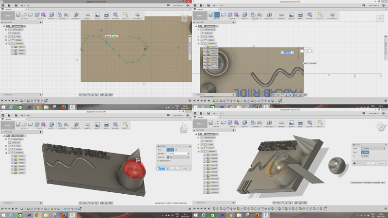
Final object to 3D printed and tested
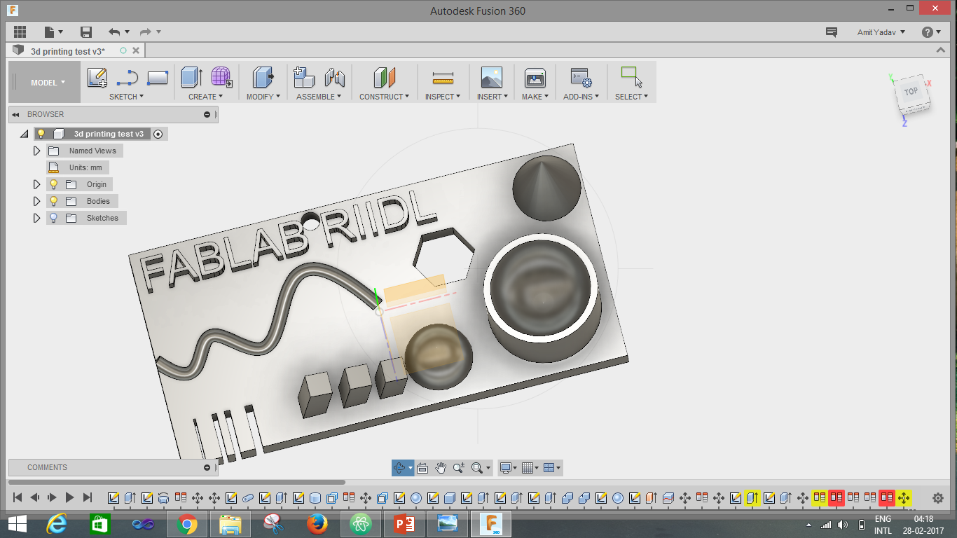
Rendered object :
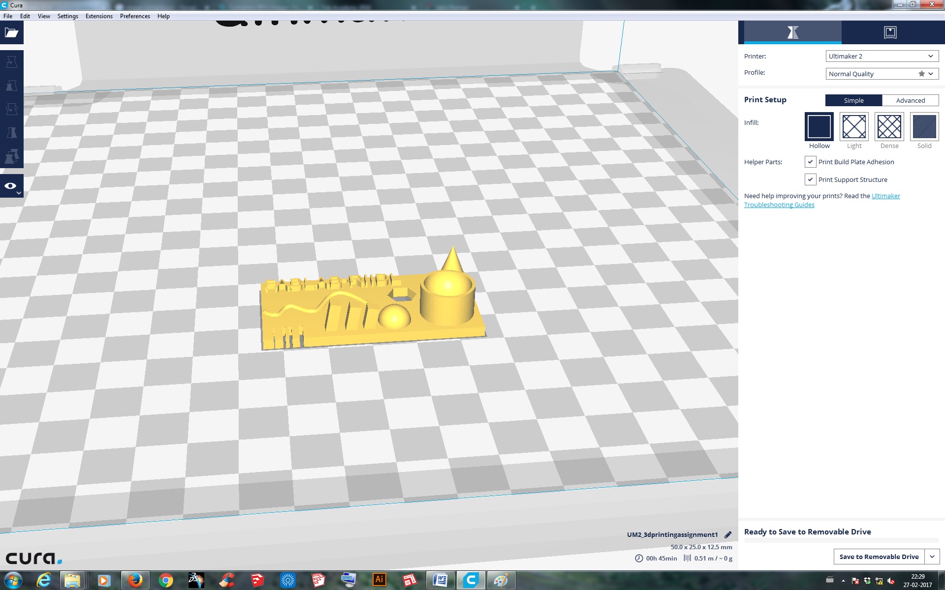
For Printing
We printed this object on Ultimaker 2 with following the same process that I used for Pen&pencilstand
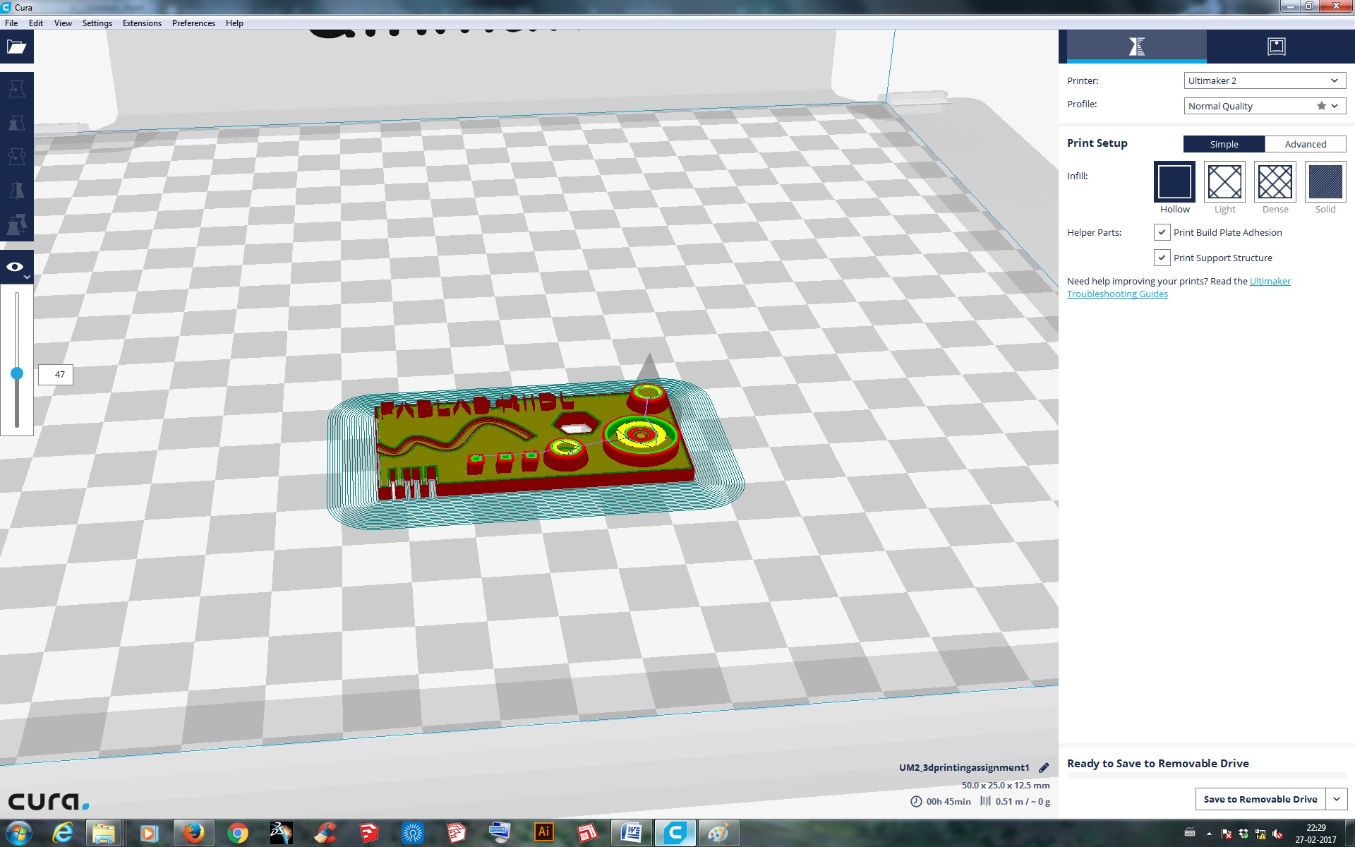
Final output:
