GOAL OF THE ASSIGNMENT
In this assignment we have to make an in-circuit Programmer by milling using Milling Machine and try to make possible as final project PCB.
Let get started with Assignment
For that we required some basic background of the electronics. Since I am Electronics Engineer I already know all this stuff.
PCB
Printed circuit board (PCB) mechanically supports and electrically connects electronic components using conductive tracks, pads and other features etched from copper sheets laminated onto a non-conductive substrate.
Different Types of Printed Circuit Boards
PCBs have copper tracks to connect the holes where the various components are located They are specially designed for each and every circuit and build construction very easy. Though, making the PCB necessitates special tools. The different types of printed circuit boards mainly include the following
- Single Sided PCBs
- Double Sided PCBs
- Multilayer PCBs
- Rigid PCBs
- Flex PCBs
- Rigid-Flex PCBs
For this assignment we have to use single side PCB as per the application.
There are few grades of PCB such as FR-1, FR-2, FR-4, CEM-1, etc.
I have selected FR-1 for this assignments.
To begin with the assignment we need to download the files for the Fab Academy 2017 class. We are interested in this three files.
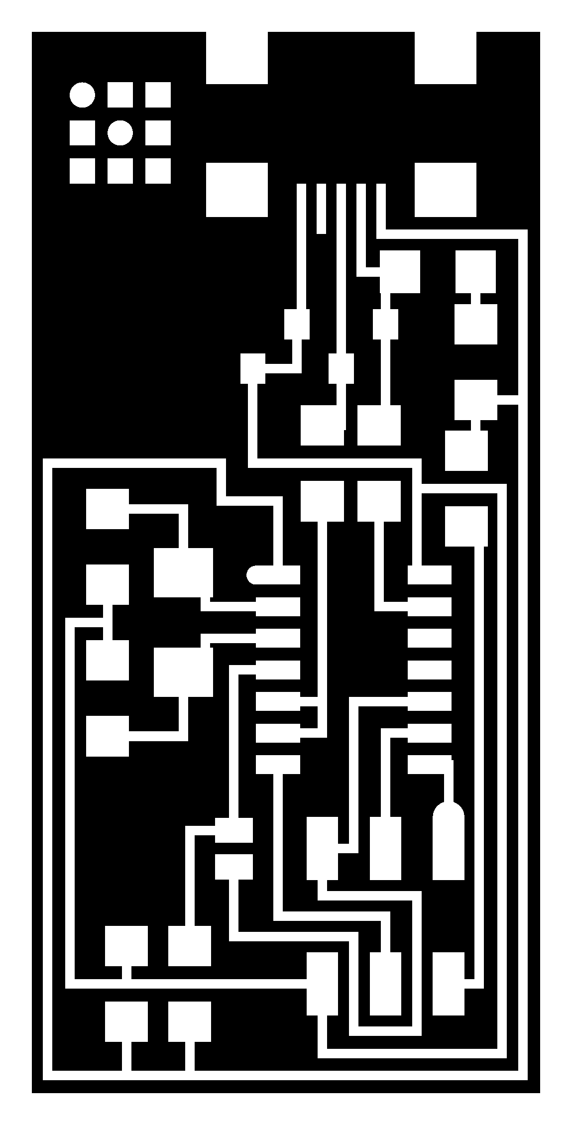
- hello.ISP.44.traces.png - This file will be used to mill the traces with 0.4mm bit
- hello.ISP.44.interior.png- This file is will be used to cut-out the board from the main PC with 0.8mm bit
- hello.ISP.44.png - This is the file will help me to solder the components in right place
Started with downloading the png file http://academy.cba.mit.edu/classes/embedded_programming/hello.ISP.44.interior.png
About Fab ISP : The FabISP is an in-system programmer for AVR microcontrollers, designed for production within a FabLab. That is, it allows you to program the microcontrollers on other boards you make, using nothing but a USB cable and 6-pin IDC to 6-pin IDC cable. It's based on the USBtiny and V-USB firmwares, which allow the ATtiny44 to perform USB communication in software. Programming can be done through avrdude. The schematic (PDF) is super simple: USB connector, ATtiny44, and 6-pin ISP header, with assorted passive components. I started with the Eagle files for the USBtinyISP, although there's almost nothing left of it. Most of the parts for the FabISP are in the FabLab inventory. Exceptions include the Mini-B USB connector (SparkFun, Digi-Key), 12 MHz crystal (Digi-Key), and 18 pF capacitors for the crystal (Digi-Key).
Website url : http://fab.cba.mit.edu/content/projects/fabisp/
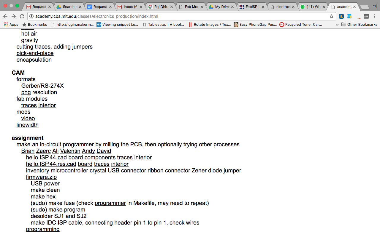
Scrolling down to the download section. Where I downloaded two files traces and interior.
FAB MODULES
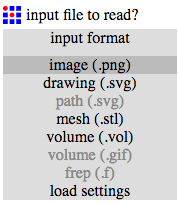
Once launched, we can open the PCB traces files to the FAB Module with the input file option and selecting .png format. And then selecting the output format for Roland Mill.
After downloading the files. Its time to do the configurations according to the Milling machine. For that I have used Fab modules.
The Fab module is the interface between the input design image and the machine. It converts the input file into selected output file on the Node JS server and passes on to the machine u select. The interface is via USB cable.
Upload the file (hello.ISP.44.traces.png) on "Input section" select .PNG
Now select the Output format according to the need. In my case it is .rml Because we are doing milling and the machine used for that is Roland Modela MDX20. It uses the file format of .rml to read.
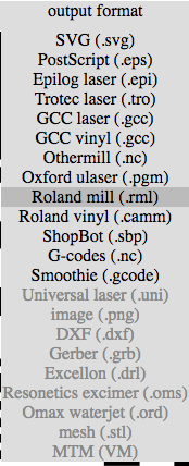
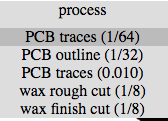
After selecting the output format select Process. Since we are doing traces on the PCB. Select PCB traces (1/64). To do the outline select PCB Outline (1/32). Also according to that the end mill will change.
Connect the machine via USB Port. The machine which I was using had a Serial port so had to use USB to Serial converter.


Now lets start with the milling process.
Milling?
Milling is the machining process of using rotary cutters to remove material[1] from a workpiece by advancing (or feeding) in a direction at an angle with the axis of the too
For PCB Milling I am going to use MODELA MDX 20.

Now we need to setup the material required for the assignment
Please look at the image below for the materials
- PCB Board FR-1
- Double side tape
- End mill tools
- Alan key
Now I know that I'll be milling the board to make the PCB that means machine will be removing the excess. Yes, it's the subtractive manufacturing technique. So that I've to take care of the machine as will as the board. So, as per the Neil's word I to use an underlay board, which will be fitted directly on the metal surface of the Modela machine while the main target board I've to place on top of underlay. This arrangement helps to safeguard the bit as will as the metal platform.
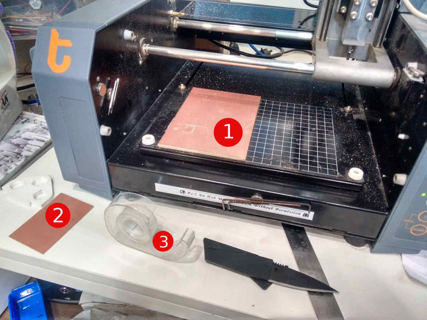
In the image above you can observe the numbers, each of them I'll be explaining in brief as follows.
- It's the underlay board which will safeguard the Modela MDX-20.
- It's the target board on which will be milling our circuit.
- Double sided tape which can be used to stick the target board to the surface of the underlay board.
Grabbing the end-mills (tools)
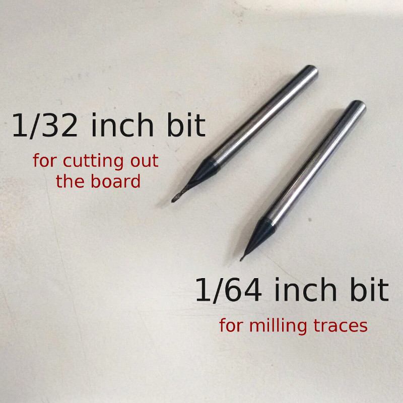
So, mill the trances I'll be using the 1/64 inch bit and 1/32 inch bit to cut the board.
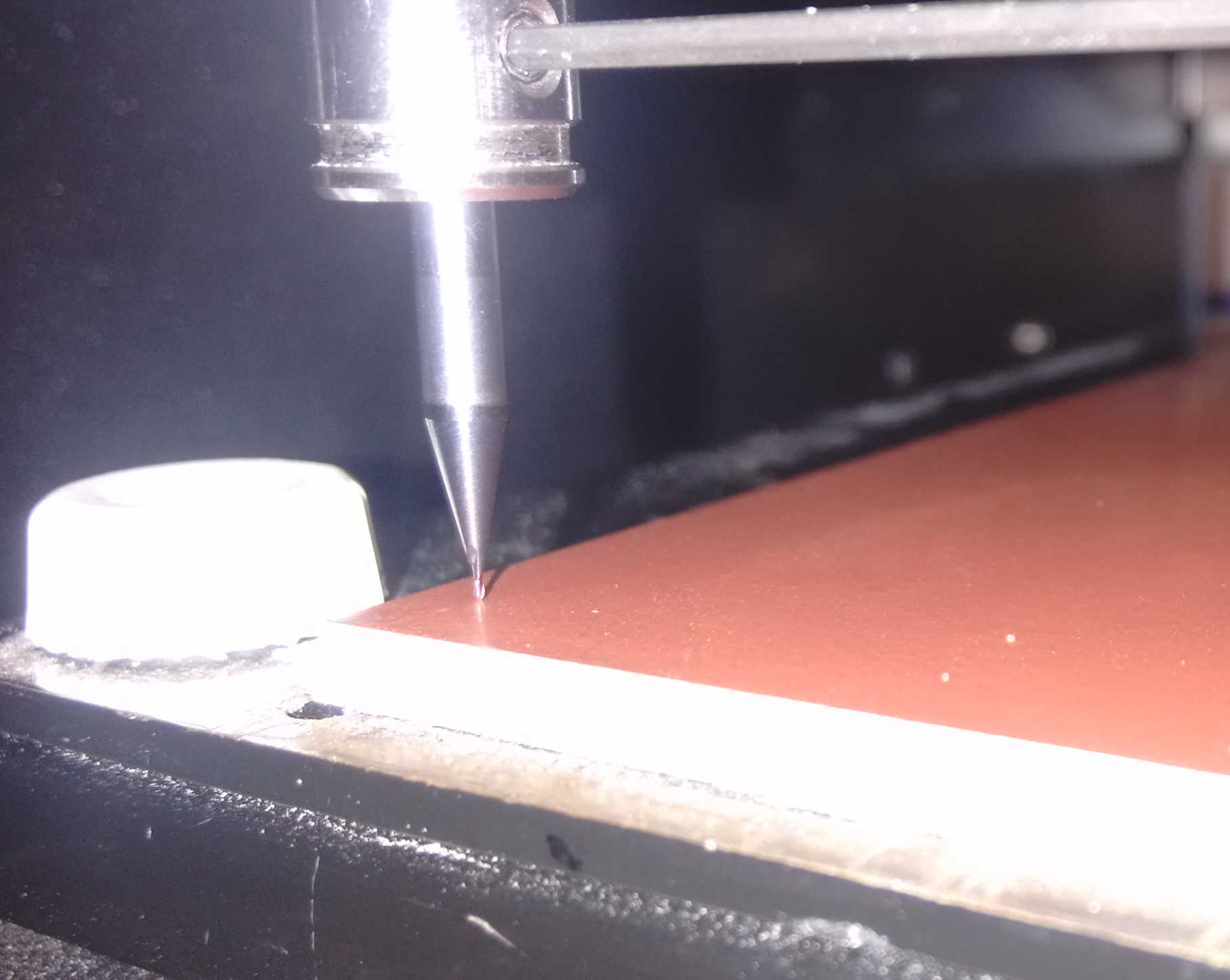
Bit Adjustments and Milling process
Adjusting the end-mill: end mill is supposed to be adjust exactly touching the PCB surface not piercing the PCB as shown in the figure.
1. Insert a cutting tool in a collet.
Do not insert to the portion of an edge. When you use included cutting tool,
refer to the following figure.
2. Tighten the set screw with hexagonal wrench.
3. Click [View] of VPanel.
A spindle head moves to a center and a table moves to the front.
4. Loosely tighten the collet with cutting tool.
Insert the collet, and then loosely tighten.
5. Fully tighten the collet.
Tightly secure the collet by using two spanners.
Explained in the previous assignment i.e. ELectronic production
Double side tape for holding the PCB on the Modela bed

Process

While Modela was too busy with the Job - Milling Tracks the end mill(1/64 inch) rotates super fast and removes the top copper surface of the PCB which in results makes the tracks.
Board is milled!!


Now we have our the boards milled. Now, we can populate the board with the components. To pick the perfect board you have to check out the edges of the traces. If they are super sharp that means the board is perfectly milled.
Components:
| 1 ATTiny 44 microcontroller | 1 Capacitor 1uF |
| 2 Capacitor 10 pF | 2 Resistor 100 ohm |
| 1 Resistor 499 ohm | 1 Resistor 1K ohm |
| 1 Resistor 10K | one 6 pin header |
| 1 USB connector | 2 jumpers - 0 ohm resistors |
| 1 Cystal 20MHz | 2 Zener Diode 3.3 V |
| one usb mini cable | one ribbon cable |
| two 6 pin connectors |
Populating the board
How to I solder the my Components:
1. I put a drop of Solder on the SMD pads of the IC.
2. Then I align the IC pads with the pads on the board.
3. After I heated the solder drop on the board and it melts and fuse with the ic pads and with this my one ic pads fuse with the board and now i can start soldering my rest of the ic.
4. In Similar fashion I solder rest of the components i.e. resisitor, capacitor, header pins, etc.
In General I have written, the basic tips for SMD Soldering.
We can place the IC carefully making sure the pins are lined up as well as they can be, on some of the larger pin count packages this can be a bit difficult. In some ways this can be the hardest step.
Once properly lined up tack a few pins or use a high temp adhesive like a paper tape to hold the IC in place. Were now ready to solder it!
Start by tinning our tip, clean it and fill the bevel with a bit of solder. This "pocket" of solder will glide over the pins heating them and depositing the perfect amount of solder on each one. Because of the flux, surface tension and temperature differences the solder makes very high quality fillets that usually require no solder wick as the right amount is deposited at each transition.
The key here is to make sure the is enough solder on the bevel to make good connection, but not too much to over load the "pocket". Drag time should be kept minimal but there should be enough time for a wetting action to occur. A good initial time is about 1 second per pin but this depends on a number of factors, and can be sped up. But it is a good place to start at first.


Final - Milled and Populated board

Hero Shoot

Programming the Board
Prelimiary Test
I performed the smoke test by just pluging my FabISP board with a MINIUSB cable to my Computer and checked what notification Computer give by just suppling power through Board.
So fortunately my this test went Fine. Computer showed no error after plugging the Board.
Now the real test was to Program by using a Programmer. So here I used a fabisp to program by FabISP board.
Secondary Testing
Yep, my primary test was successful and now I'll be moving further ahead for the secondary test.
Setup
For the secondary test I wanted to have another micro-controller board which I know that it's working so, I pulled out the Arduino board which I know that I was working and connected it to the FABISP using the jumper wires. The connection between the two were as follows.
| FABISP | Arduino Uno |
|---|---|
| MISO | MISO |
| MOSI | MOSI |
| SCK | SCK |
| GND | GND |
| VCC | VCC |
and power up the Arduino using it's own power cable.
Then I connected my FABISP to the BOX using mini USB cable and issued the command to read out the fuse bits of the micro-controller present on the Arduino board (Atmega 328).
Command is as follows:
avrdude -c usbtiny -p t44

In the image above:
- The Blue board (FABISP programmer made in Fab Academy 2016)is the programmer board which I borrowed from my Instructor Yogesh Tahmane for this assignment.
- The other one (FABISP) is the target board on which we want to make the programmer.
Below are the step/images that I have done while programming the FABISP.
Checking my board using another FABISP

Error created if you just type make

Programming my FABISP
Copied form the fabisp website : A window will open containing the Makefile. Go to the line that says: #AVRDUDE = avrdude -c usbtiny -p $(DEVICE) # edit this line for your programmer AVRDUDE = avrdude -c avrisp2 -P usb -p $(DEVICE) # edit this line for your programmer
- If using the USBtiny programmer or another FabISP ,
- Remove the "#" in front of the line with "usbtiny" in it
- Add a "#" to beginning the line with the "avrisp2" in it to comment it out.
- save the Makefile


Testing my FABISP
This is the setup I did following setup to test my fabisp is working or not by reading the signature value of the arduino uno .

