Week 3 Assignment: Computer-Controlled Cutting
Goal:
In this assignment we have to make one group and single project, for single project we have to make fab tool kit using parametric design and for group we have to make an press fit object and cut it out in laser cutter and explain the difficult and/or problem faced during the execution to make prototype.
For Single Project:
I am going to make an snap fit of basic shapes using Autodesk Fusion 360 and cut it through laser cutter
Let begin with the work.
This is the IDE of Autodesk fusion 360 and we start with the Creating Sketch form Sketch Menu.
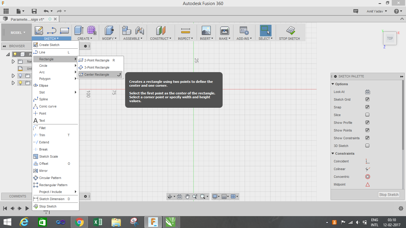
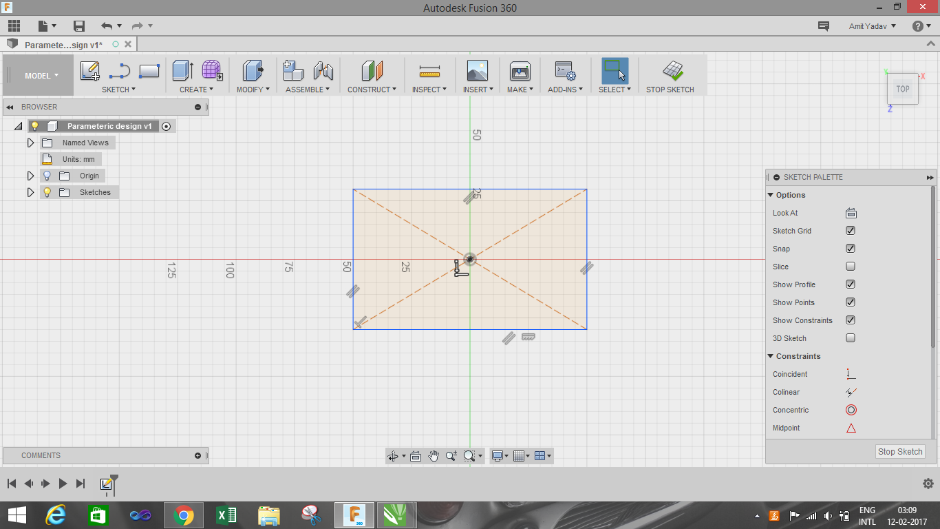
After that we have to select the one reference plane out of three. Now I want to make a shape of rectangle on this plane, for that I am going to select a rectangle for Sketch Menu. We have three options for rectangle to select, I am going to select centre rectangle as shown in image.
For parametric equation that we have to do in this assignment is done by the Parametric Equation which is under the Modify Menu tab. In parametric table there are different tabs available such as Favourite, User Parameters and Model Parameters, but we are interested in user parameters tab.
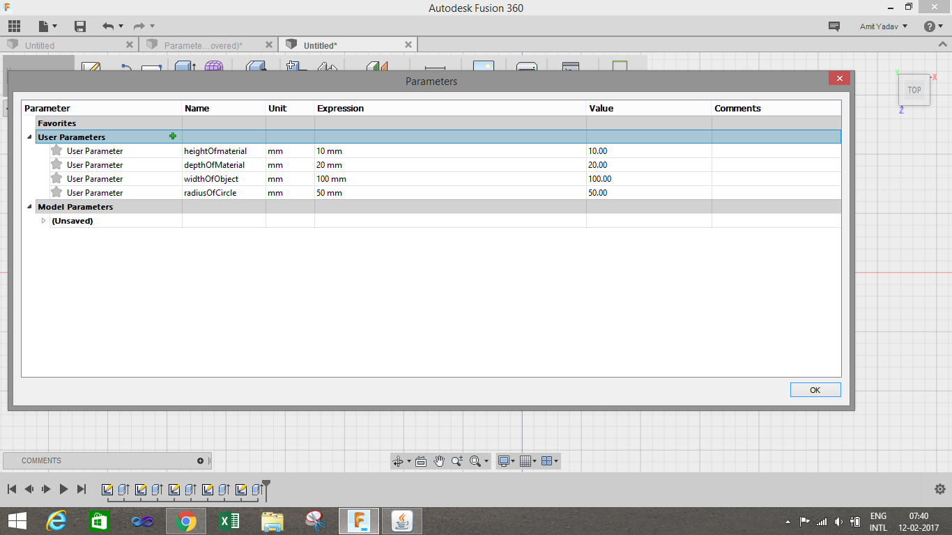
In User parameter tab, we need to add the parameters that we want to control. We need to add the parameters by clicking the add button and Add User Parameter dialog box will appear, in which we will add the parameter which we need to change after a period of time. I have added few parameters which I used in my assignment.
I used few parameters like heightofobject, widthofobject, depthofmaterial for parametric equation which I will going to use in my assignment.
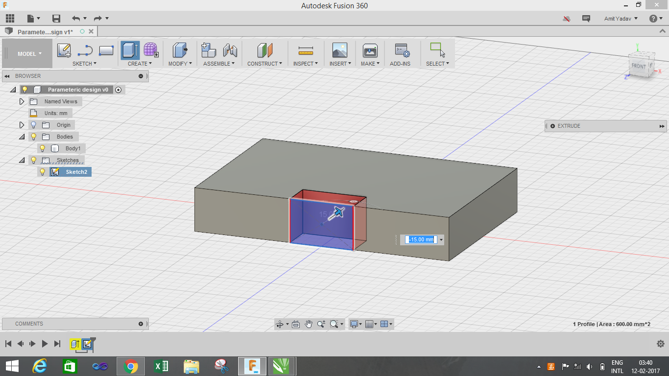
I have created a rectangle with a snap fit which will be using by other object. For making that, I used User Parametric such as lengthofobject, heightofmaterial and pull/push for extruding and creating depth along the material as shown in figure.
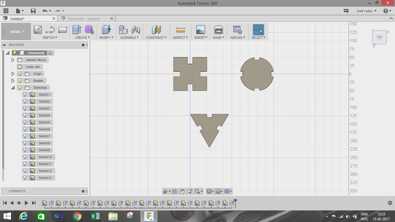
By repeating the same process I created basic circle and triangle.
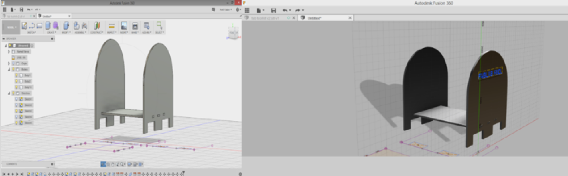
A snap fit image of all object together.
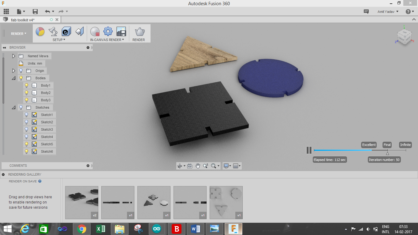
The below image is the rendering image
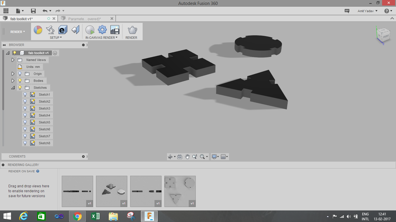
Rendering is done by the render option available in the Change Workspace Menu.
I used different option such as appearance, in canvas render for making the final output.
Final Output:
I exported .dxf file for both the towers and then imported those files into RD Works. There I had to adjust various parameters like Power and speed. Also I did some scaling on RD works to make the Towers small. After that I selected Download button and the file was imported to Laser cutter machine which was connected via Lan port.
After downloading file to laser cutter machine, there were various options on the machine. First I selected my file using "File" button. After that I placed the material in the machine and selected Origin by moving the laser head via Arrow keys. After setting the origin I selected "Frame" option to check whether the frame is proper or not. Once the Frame was set I selected "Start" button to start the cutting. This is how it looked :
Configurations :
Min Power : 85
Max Power : 90
Speed : 20
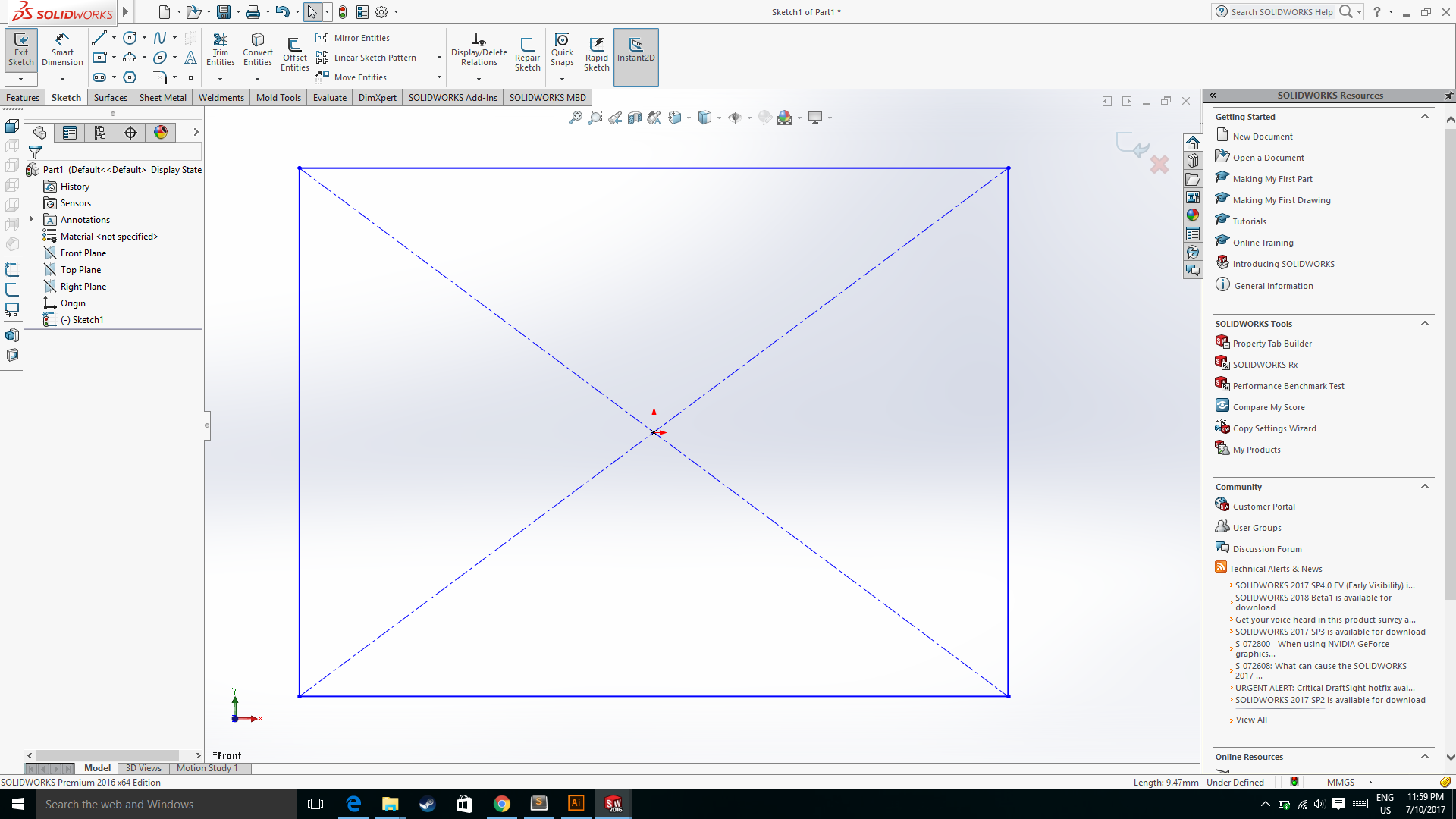
I had designed another design for the parametric assignment.
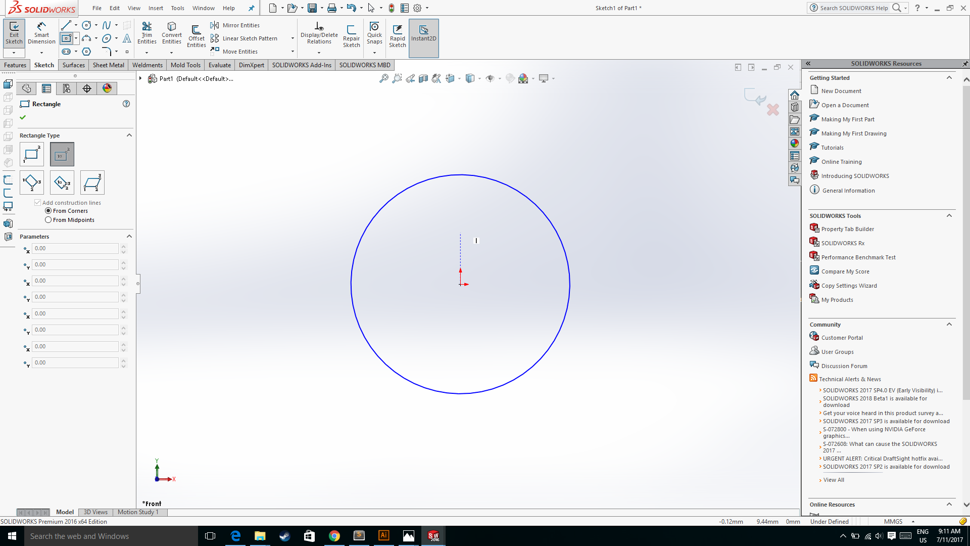
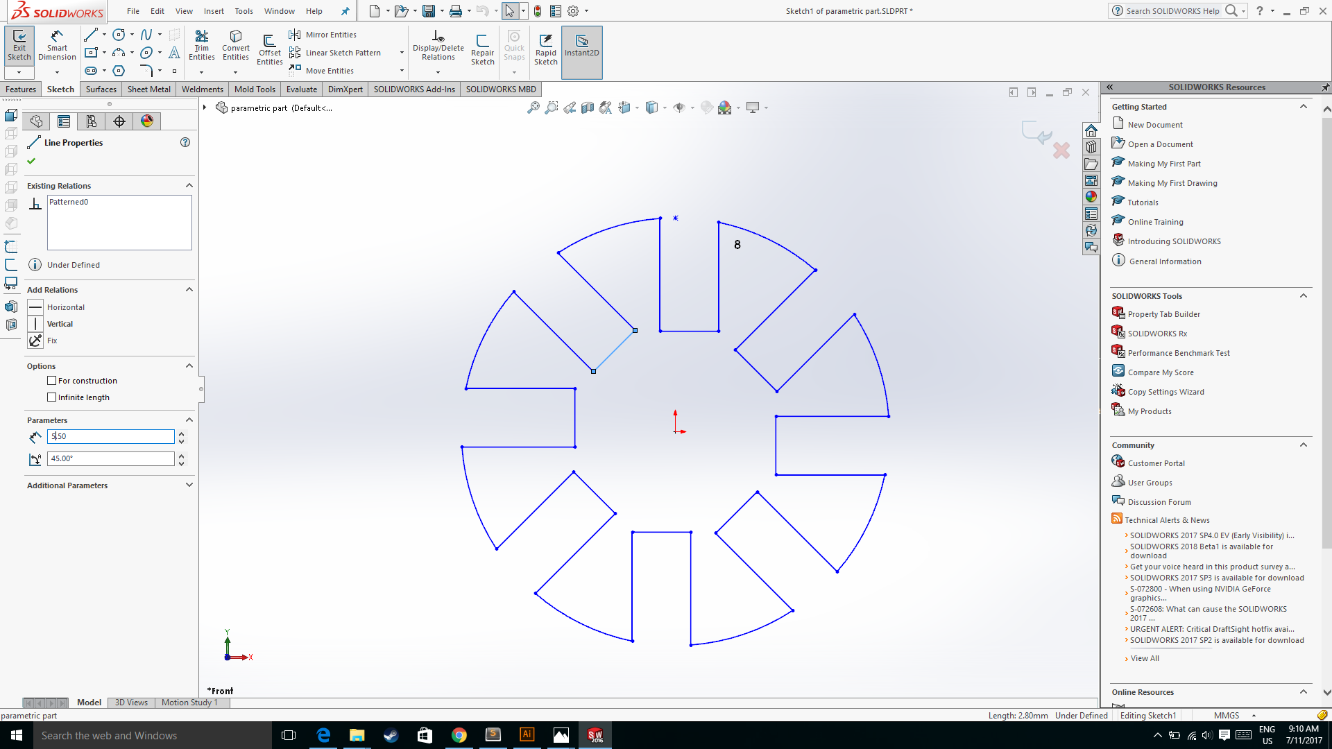
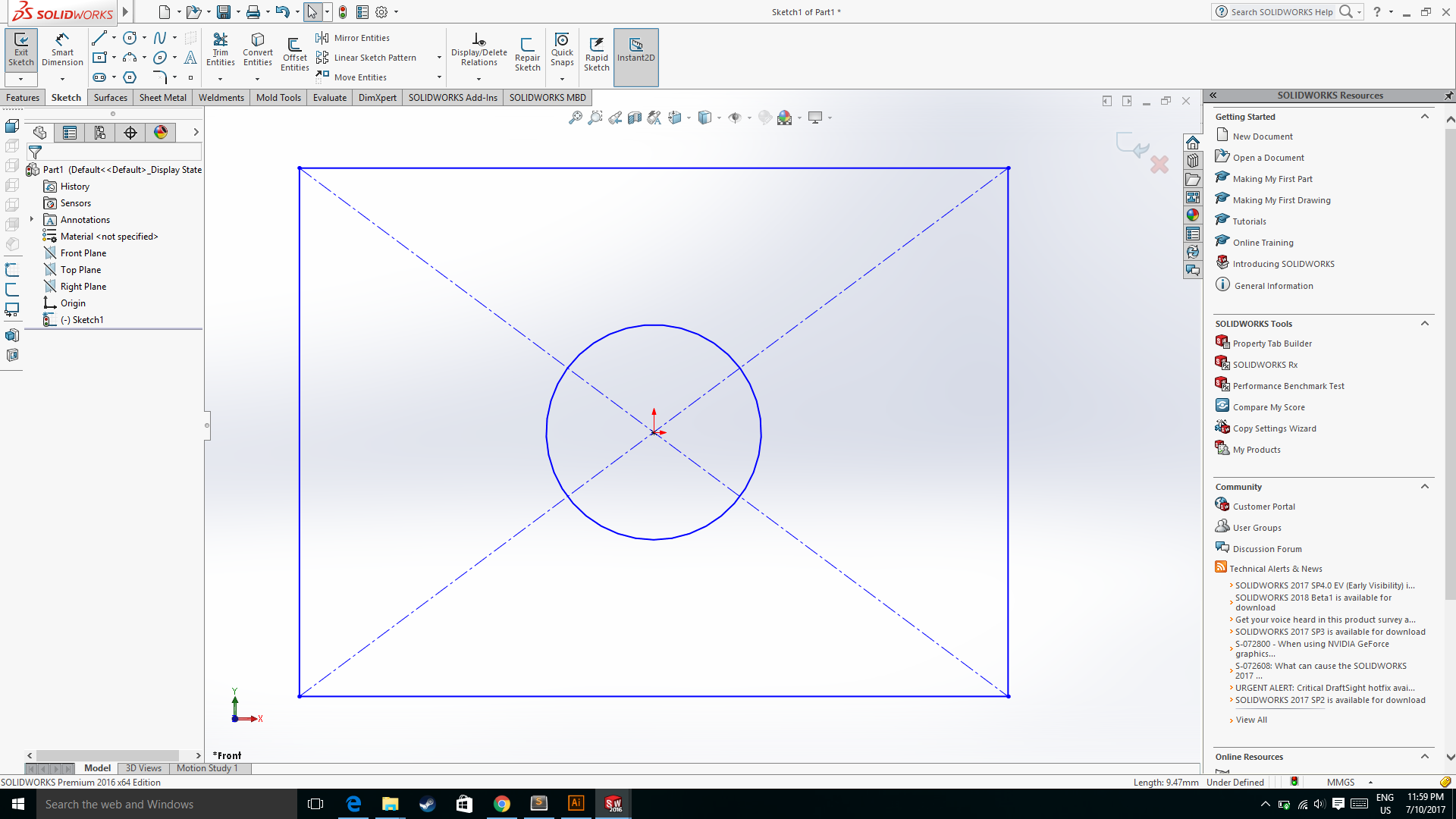
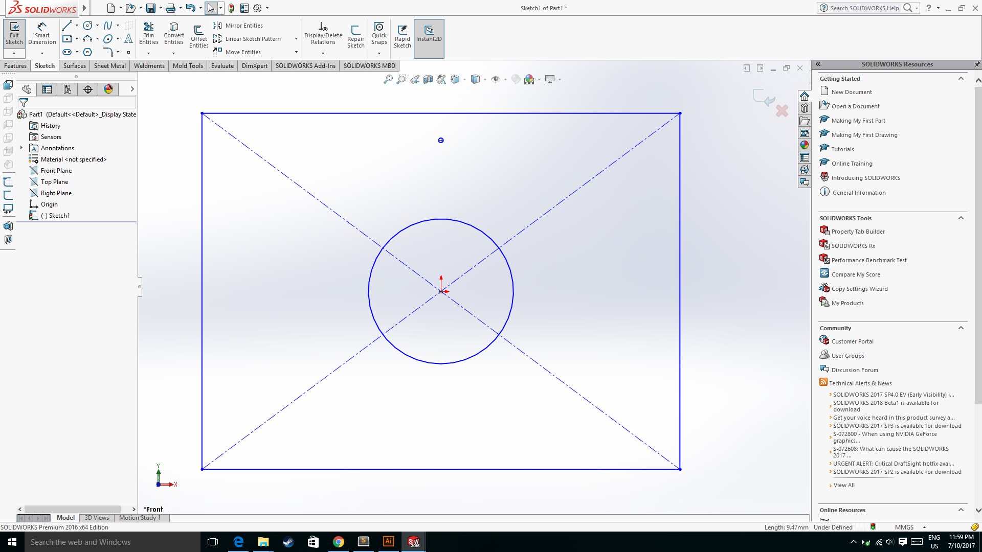
I had made a centre circle using the circle option in the solidworks.
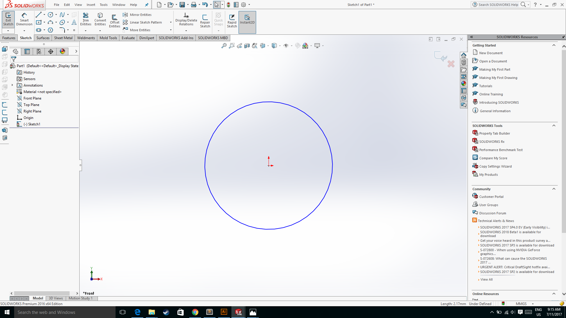
After that I used the centre rectangle which is created on the surface of the circle by prjoecting the centre line form the circle's origin to the perimeter of the circle.
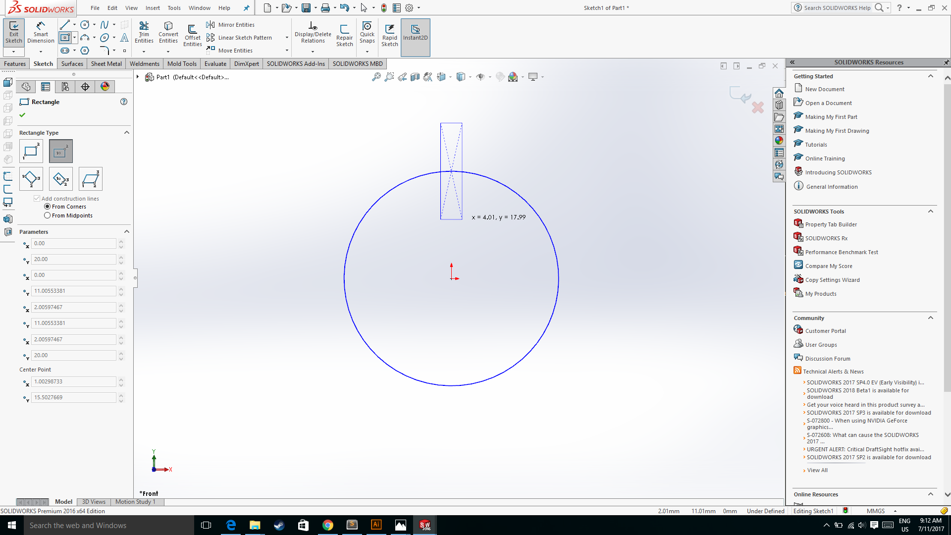
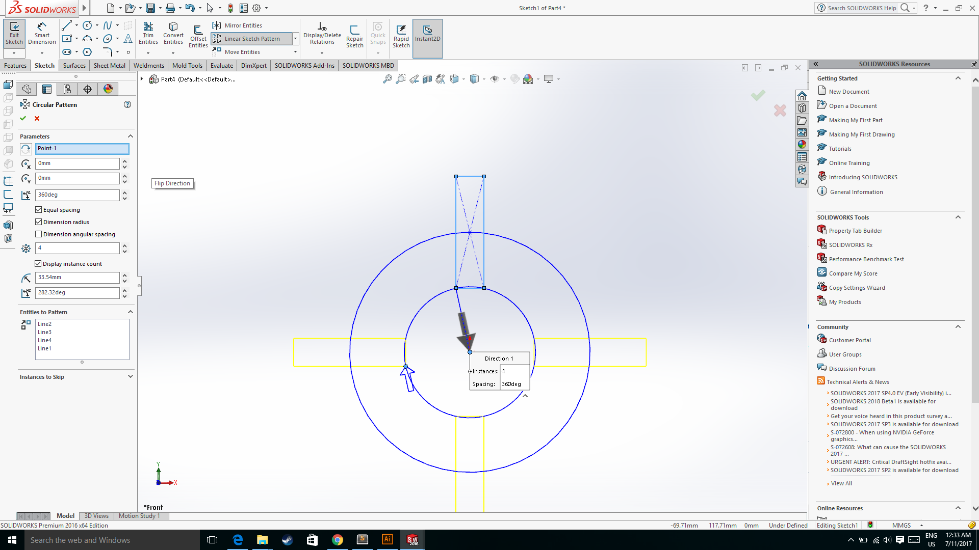
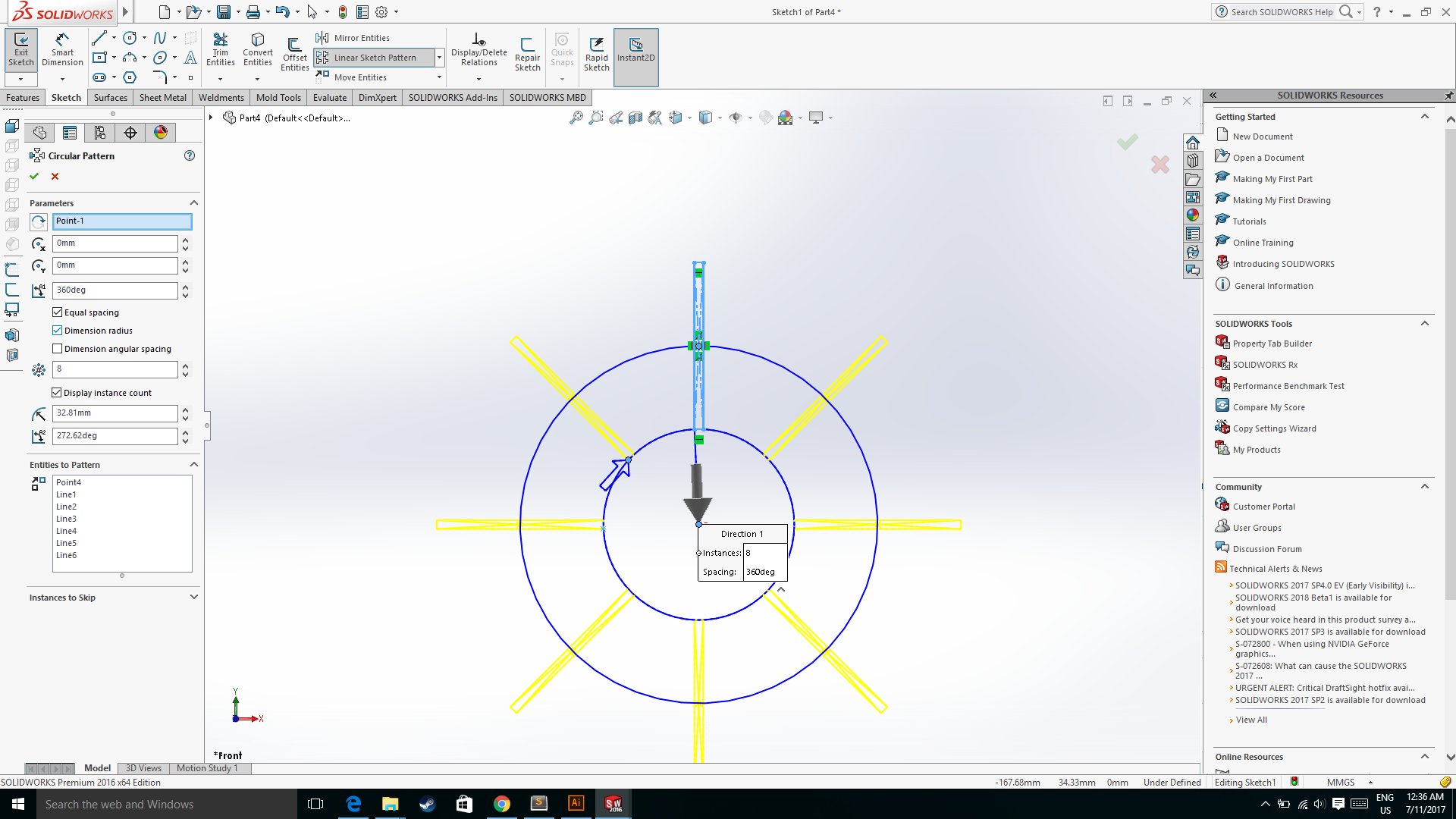
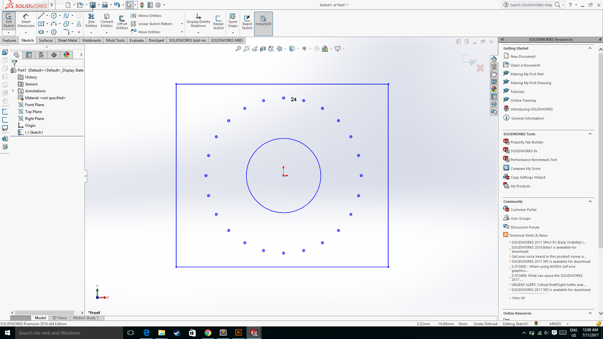
Then I used the Circular pattern which is available under the linear pattern option on the command manager bar to make the replicate of the rectangle around the surface of the circle.
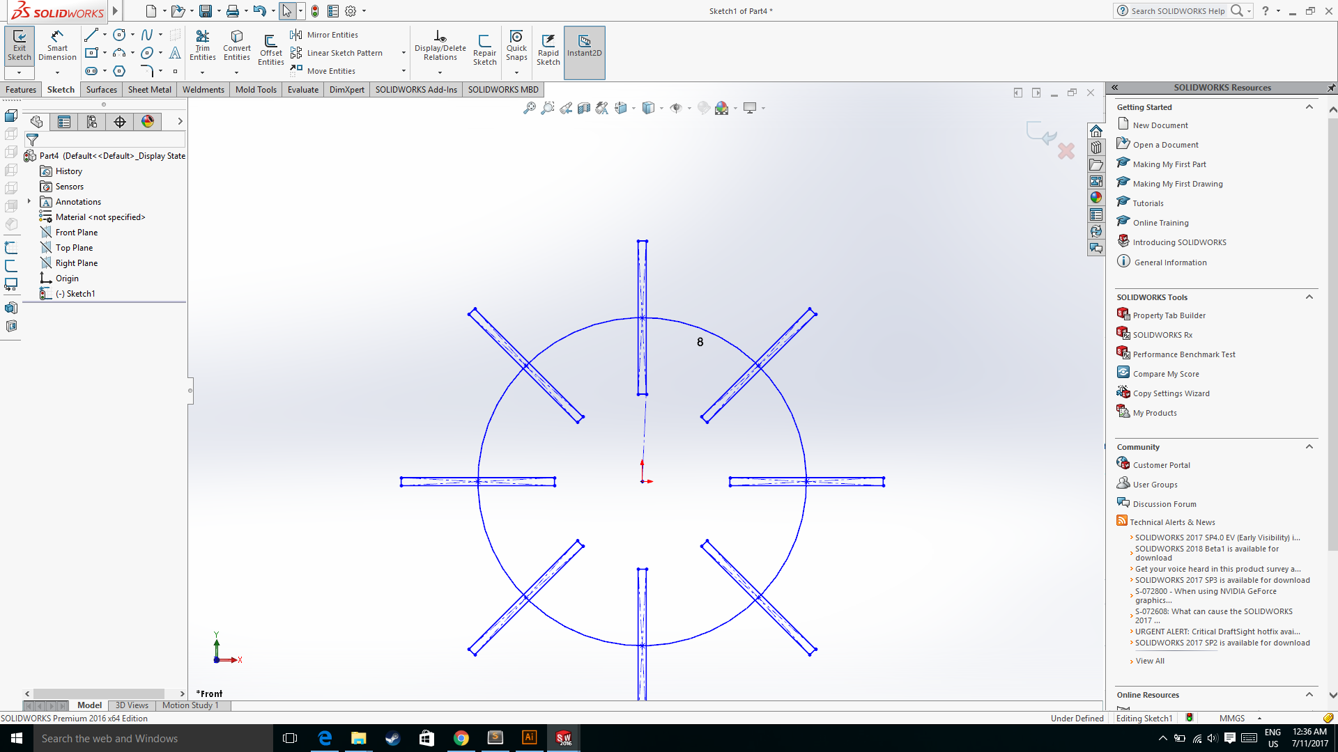
Then is used the trim option to remove the extra rectangular surface and the final part looks something like this.
.png)
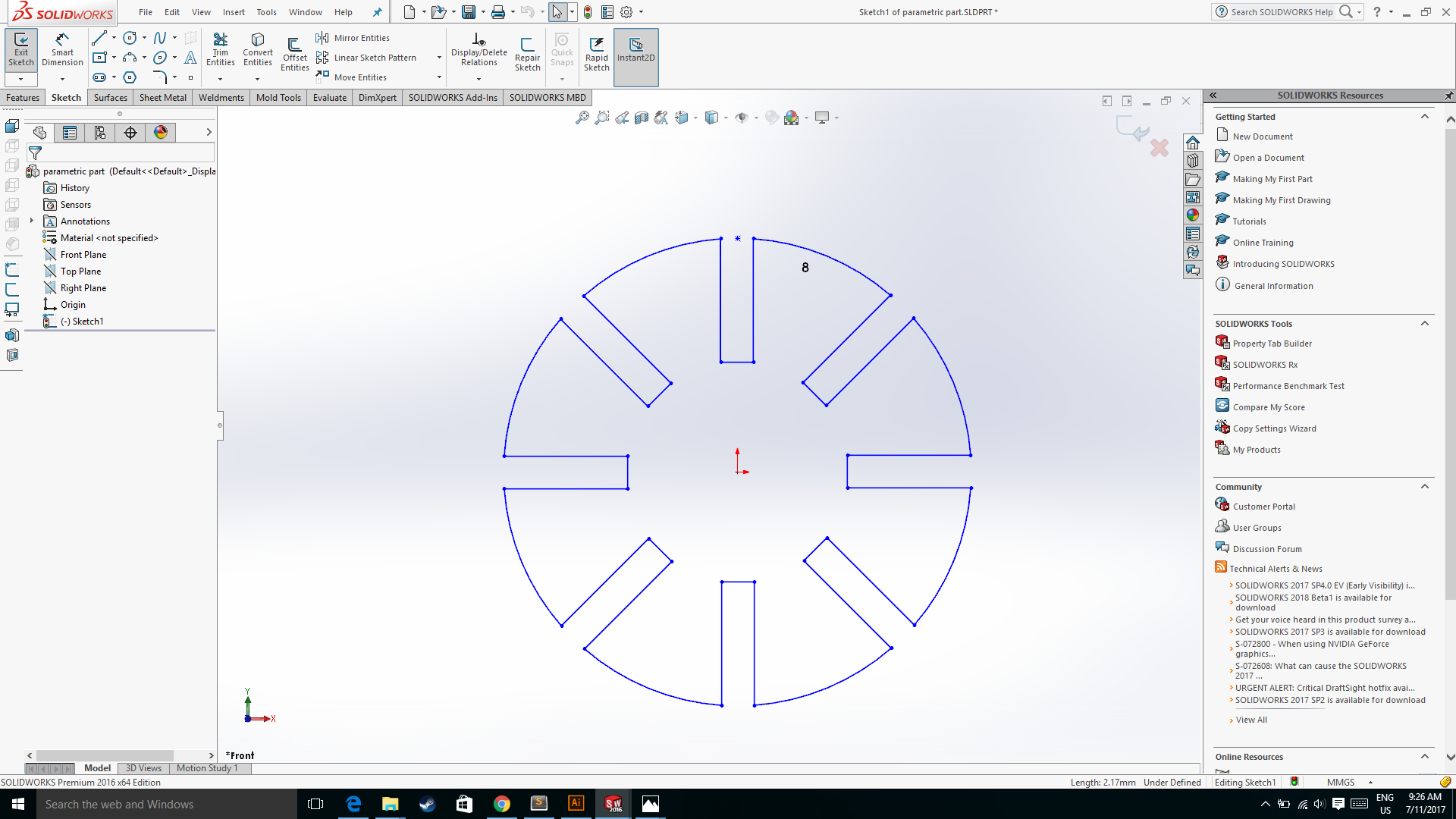
We can Change the width of the rectangle or width of the slot and according to that the circle dimension will change as per the dimension required, which is the scope of the assignment i.e. the parameteric design. I shown few images of the changing the width of the slot.


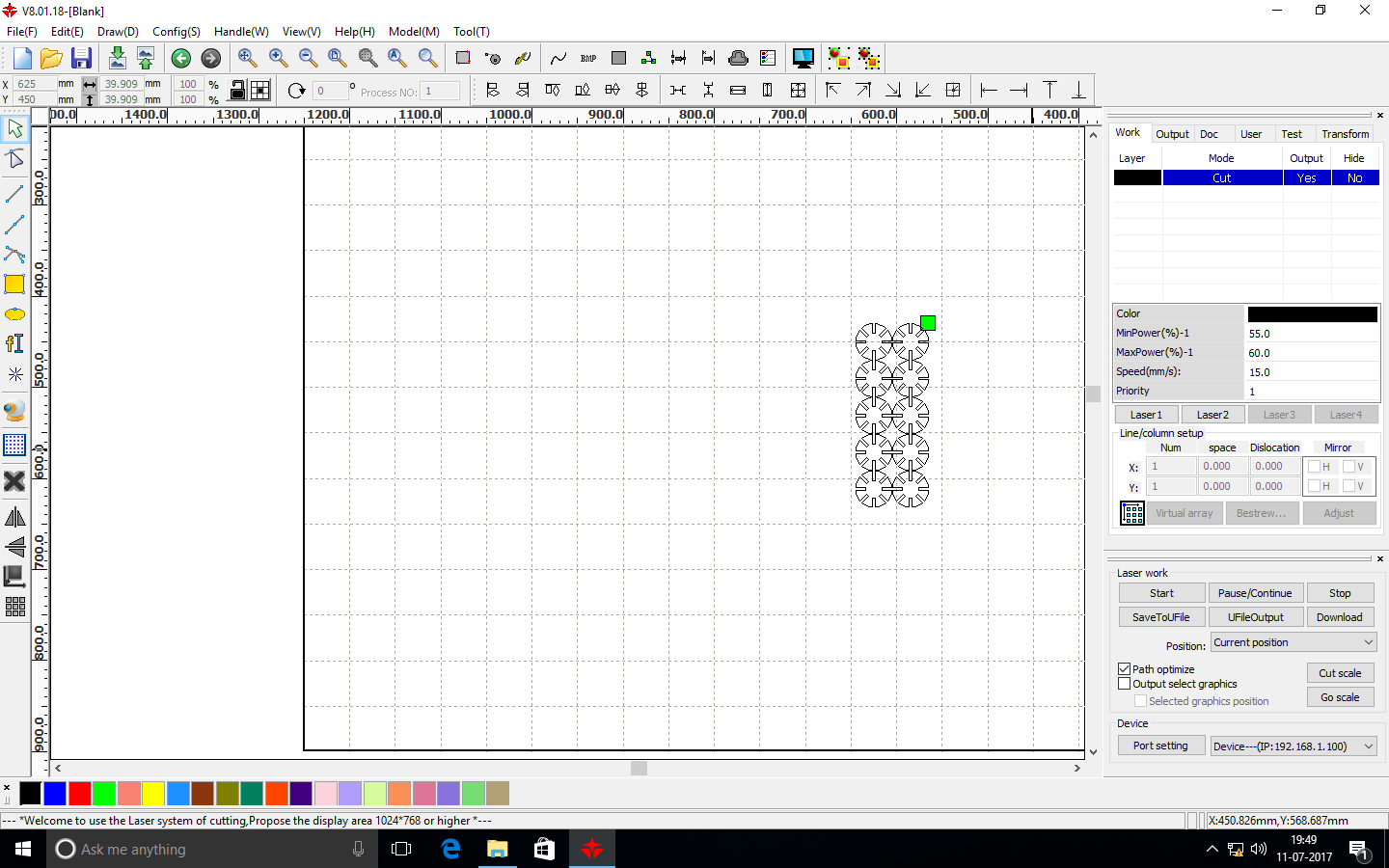
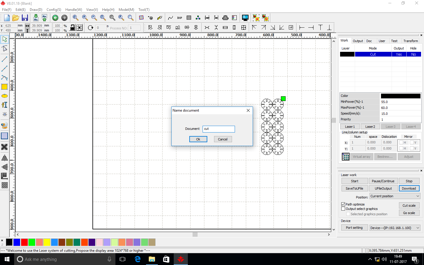
Then I imported my file to my laser cutter software and cut few parts with different dimension to cut check for the press fit combination.
Arcylic sheet - red 3.1mm thick
Laser parameters:
Cutting: Speed= 15, Power= 60
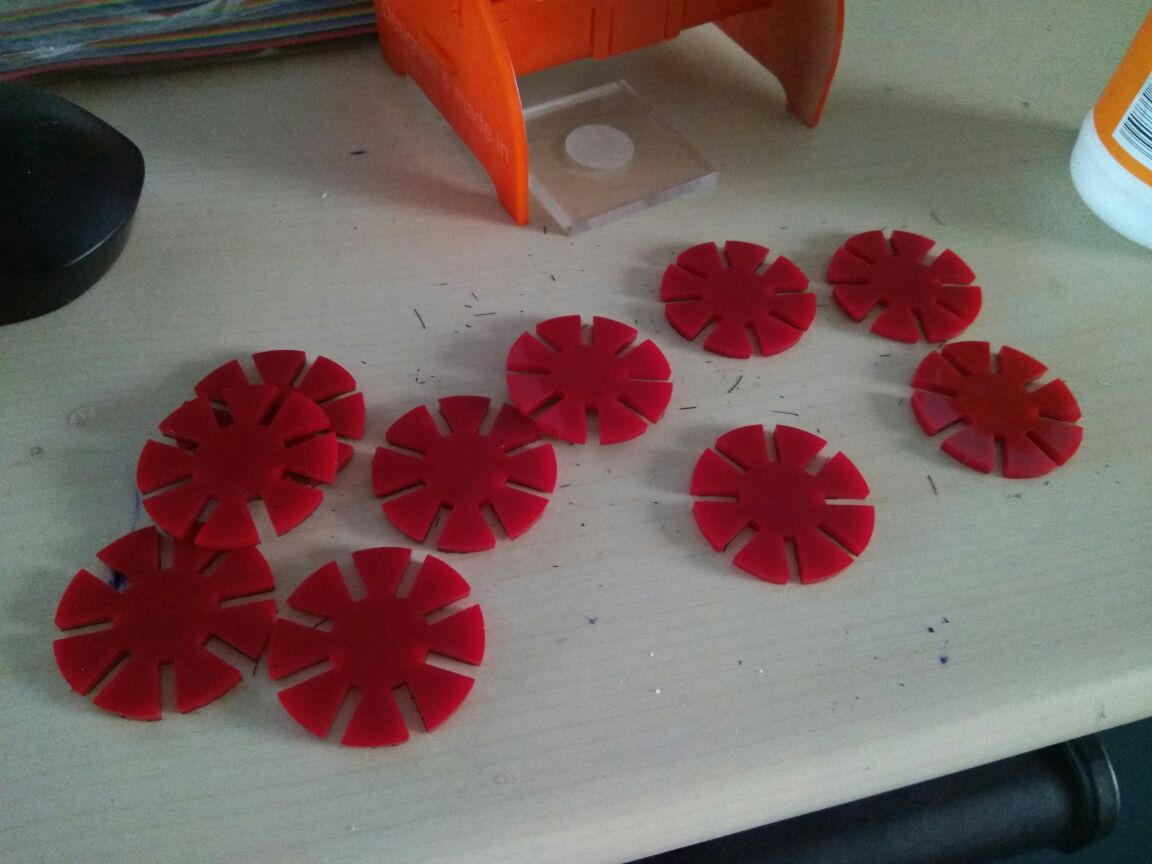
The width of the slot is 2.9mm, there is the gap in between two parts
The width of the slot is 2.8mm, in here is slightly gap.
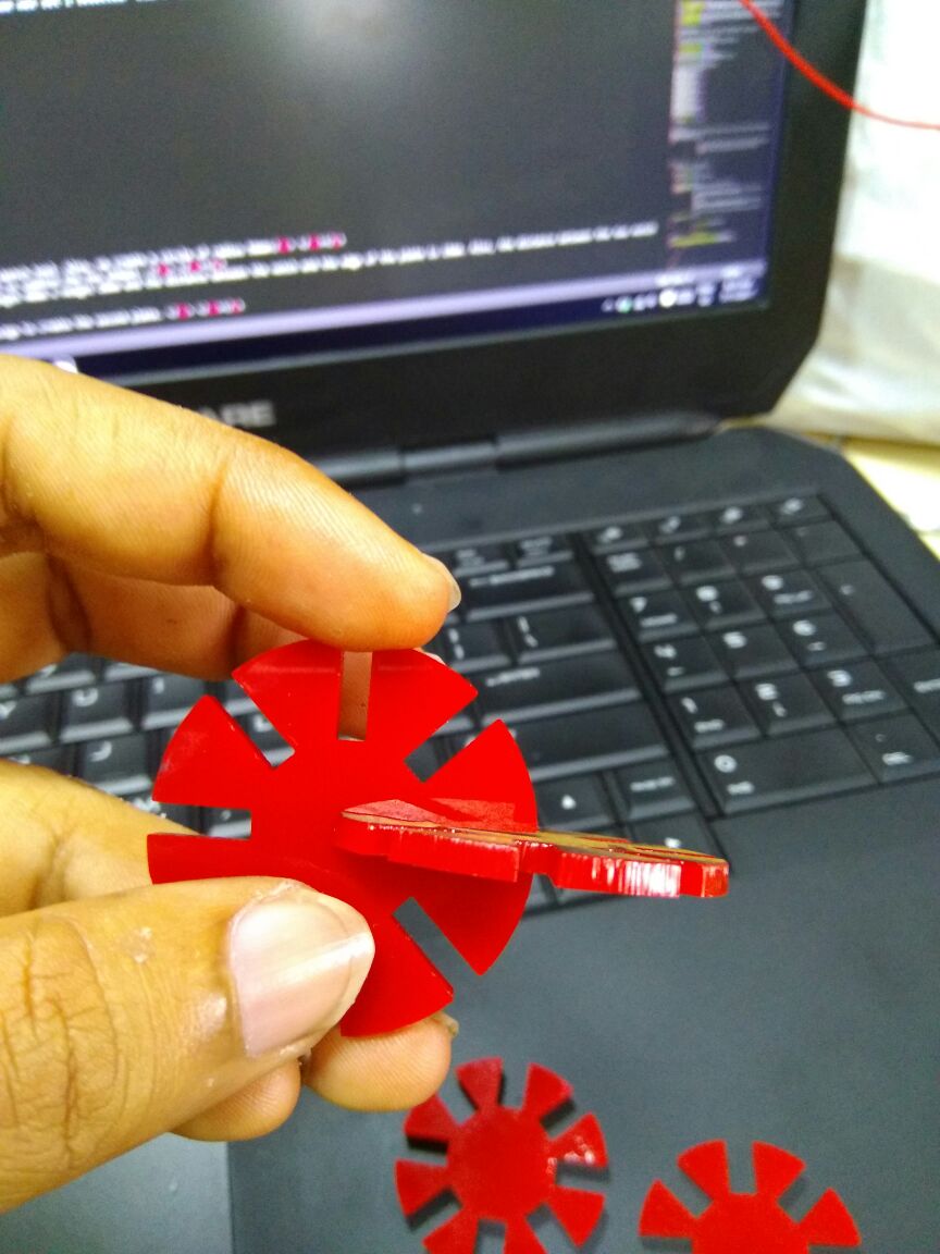
The width of the slot is 2.7mm and this is prefrectly pressfit combination that is will going to be use for my pressfit combination.
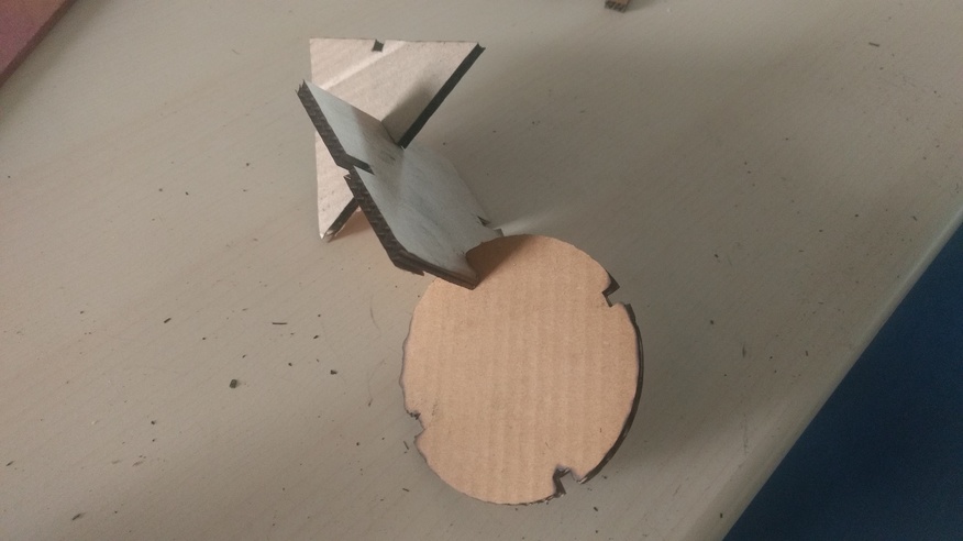
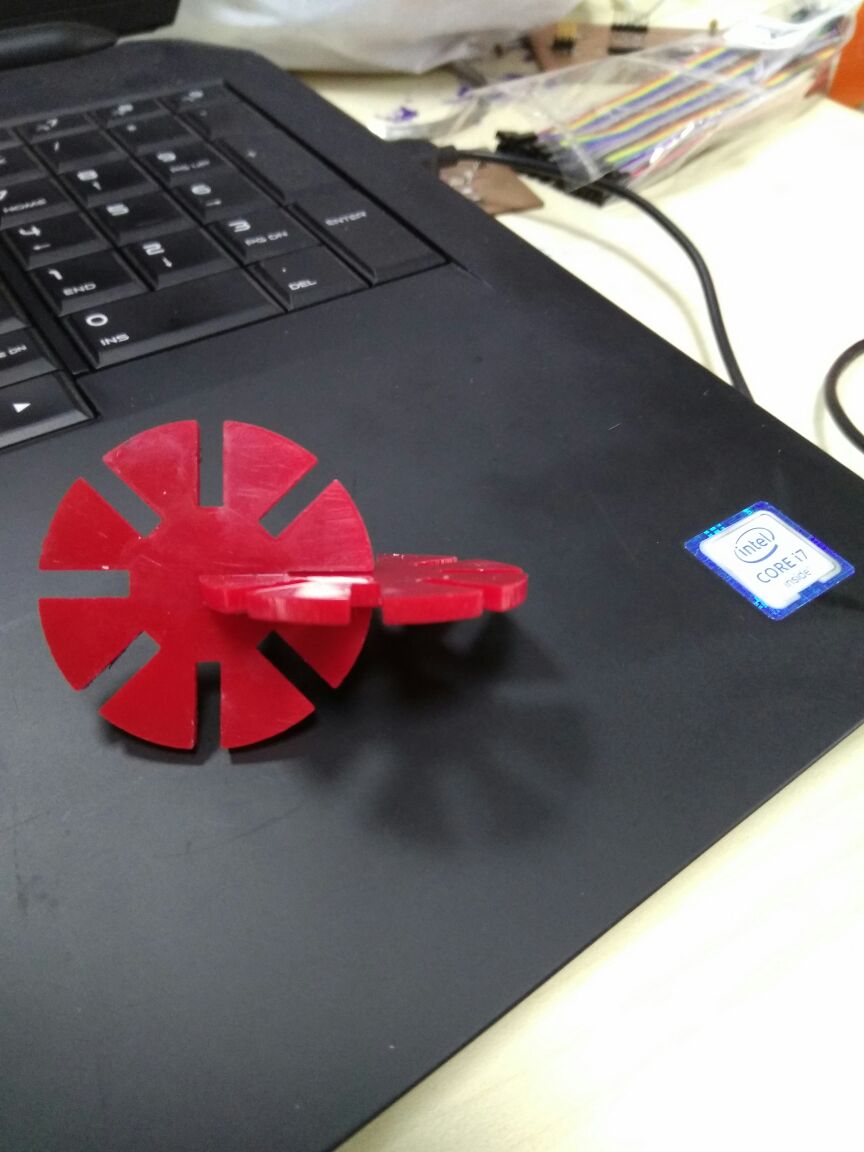
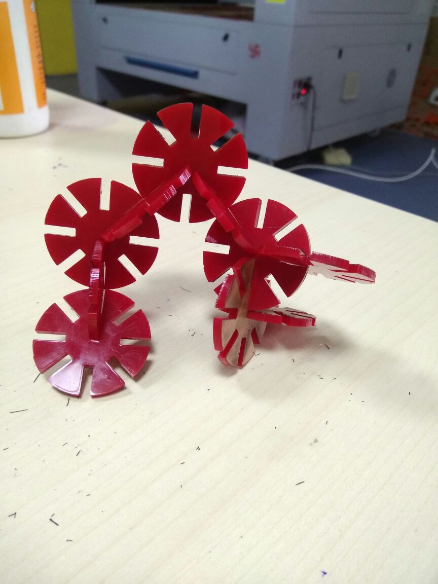
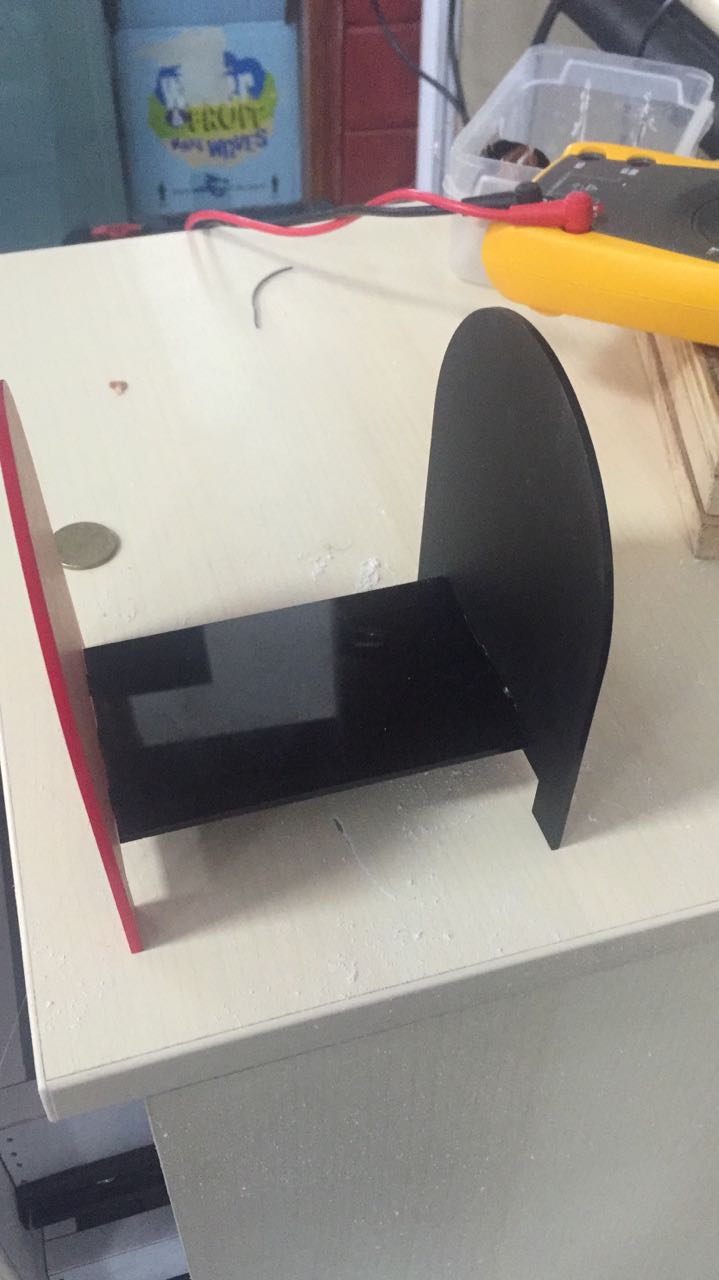
After testing for preesfit combination I cutted the parts out with the help of the laser cutting machine.
Final results
Group Assignment - Idol stand
- We created a design using Autodesk Fusion 360.
- We created a rectangle of size (l = 112mm, b = 70mm) using the sketch tool. Also, we create a circle of radius 56mm
- WE clicked the modify button and then selected the combine tool to combine the two shapes.
- To create a notch in the above plate, we created a notch of length 40mm x height 20mm and the distance between the notch and the edge of the plate is 15mm. Also, the distance between the two notch is 40mm.
- We create a copy of the same file i.e replicated the same design to create the second plate.
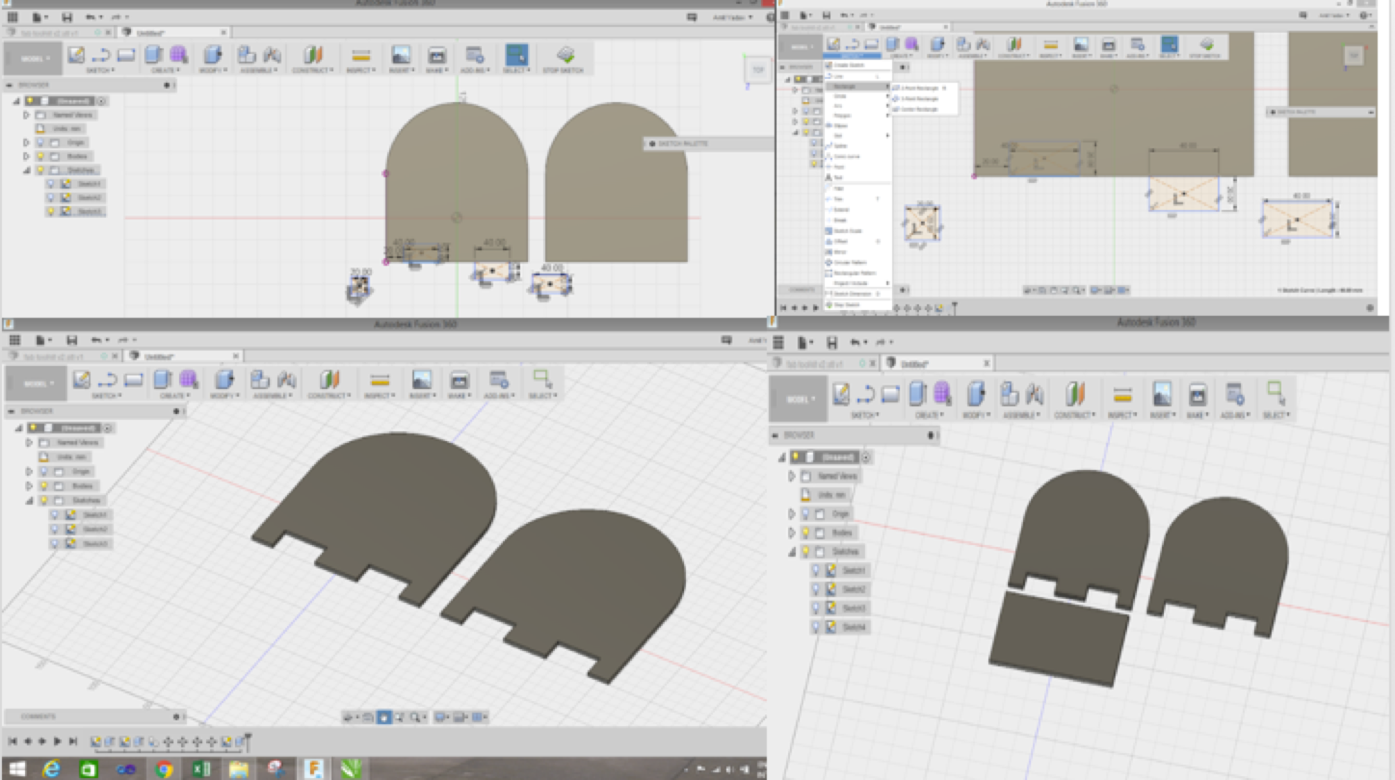
- We create another rectangle of length 112m x breadth 70mm as shown in the figure.
- We create three notches on each side of the rectangle and the created 2D, dxf files from the 3D file we sketched.
Laser Cutter Configuration
Machine type : CO2 Laser
Size : 900mm X 1200mm
Operations : Cutting and Engraving
Laser Tube : 100 Watts
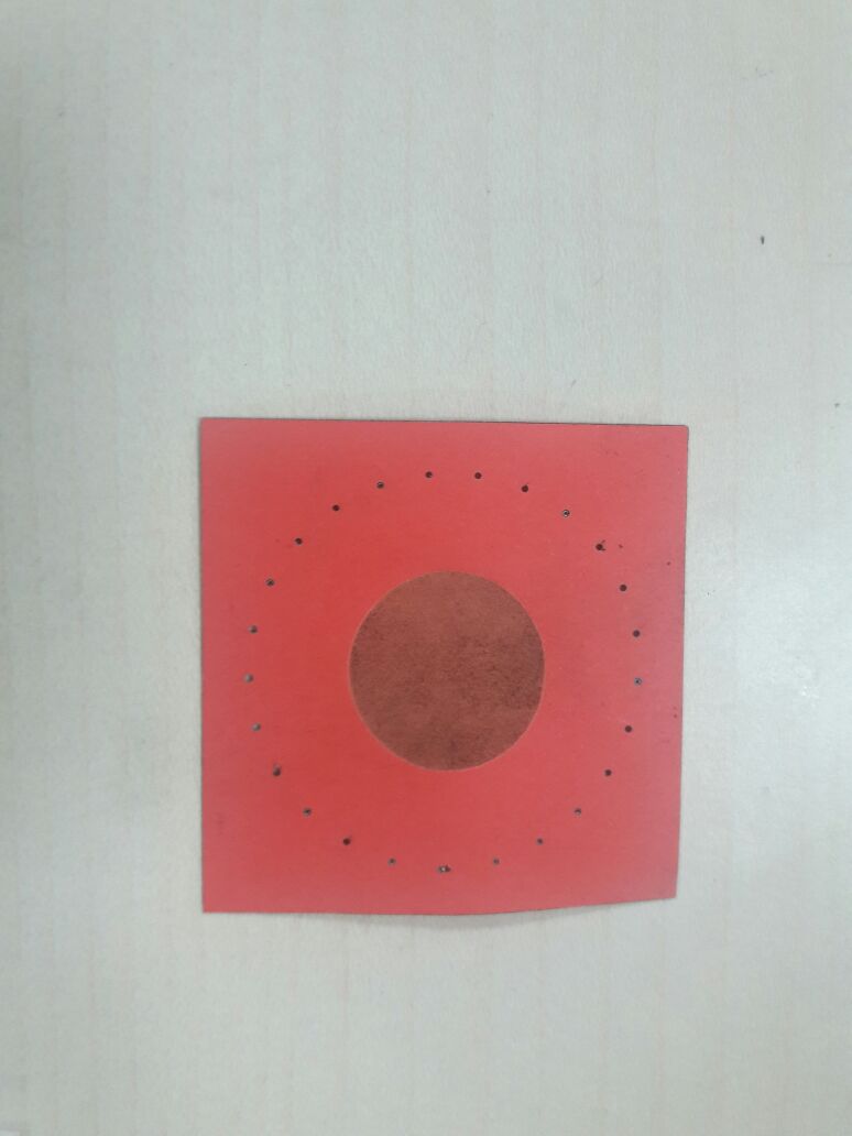
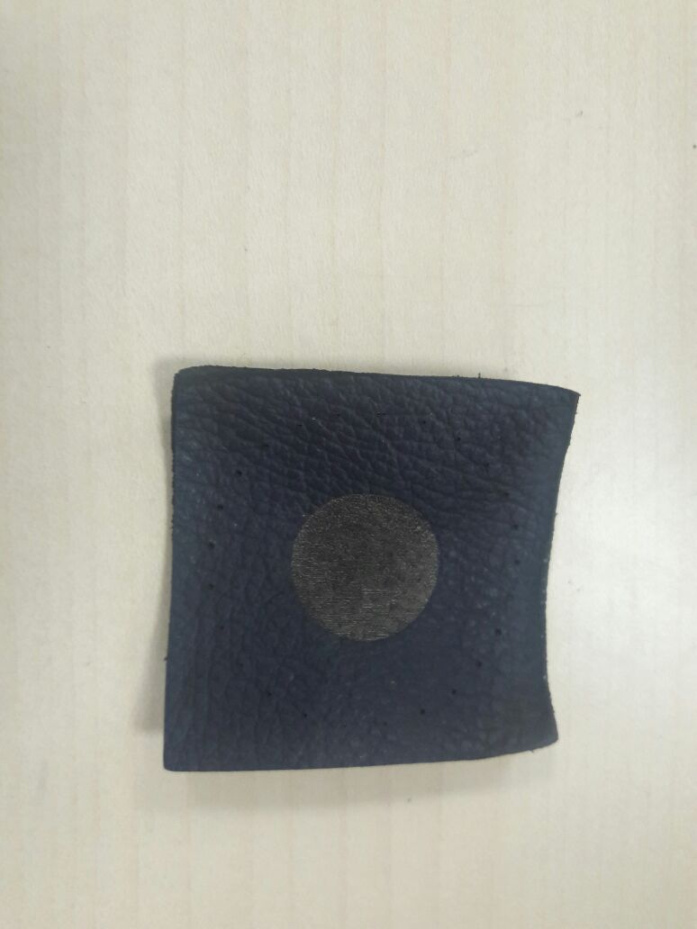
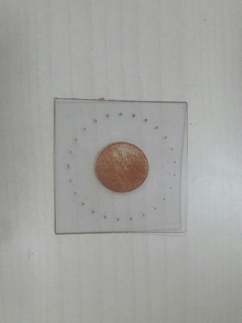
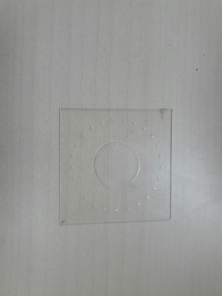
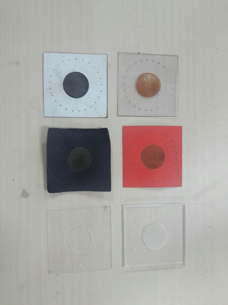
For the group assignment I have testeed out few materials.
I have made a design in the solidworks which is cirlce and small circles surrounded by it.
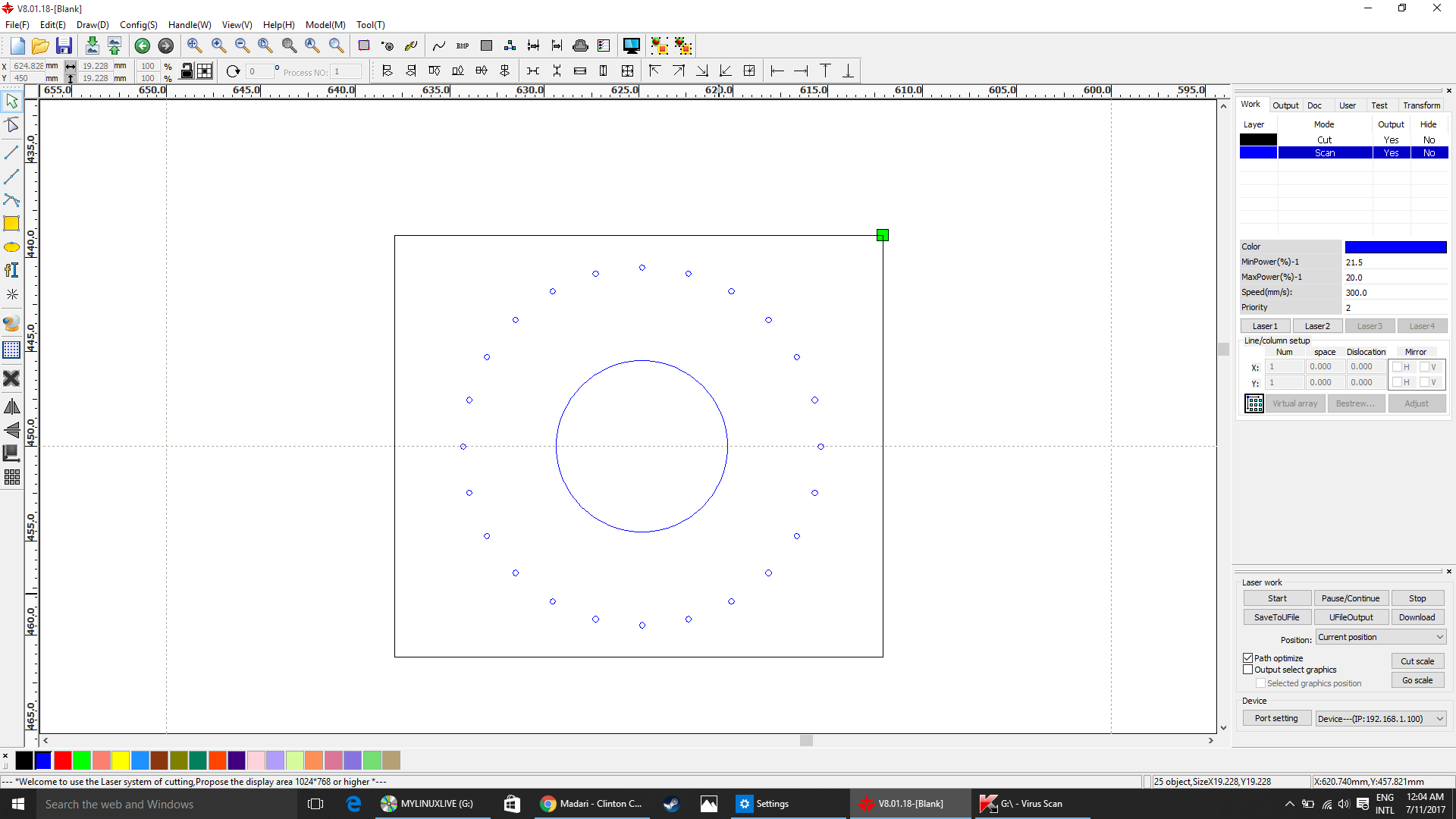
Then I Imported the design files to my laser cutter software RDworks.
The Blue color in the image is the engraving part and the black color part is to be cut out.
Materials used and the laser cutting parameters for each of it.
1. Arcylic sheet - transparent 5mm thick
Laser parameters:
Engraving : Speed =350, Power= 12
Cutting: Speed= 11, Power= 75
2. Leather - Red 2mm thick
Laser parameters:
Engraving : Speed =300, Power= 21.5
Cutting: Speed= 25, Power= 25
3. Leather - Red 1mm thick
Laser parameters:
Engraving : Speed =300, Power= 21.5
Cutting: Speed= 22, Power= 16
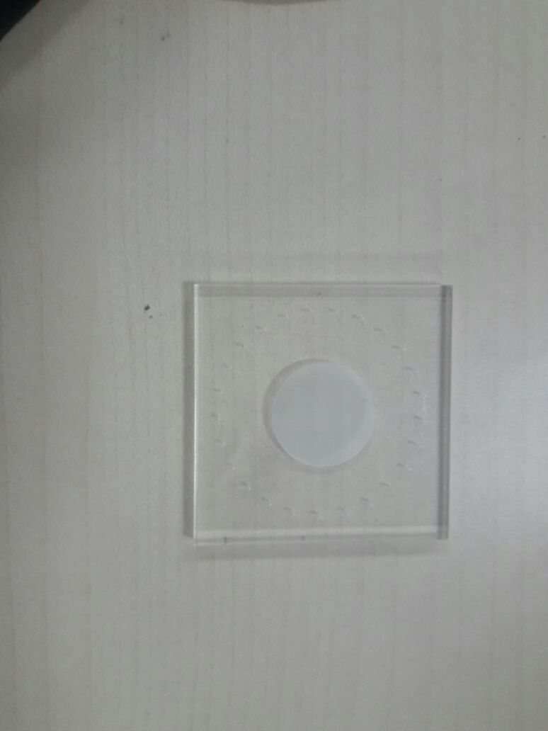
4. Glass sheet Transparent - 2mm
Laser parameters:
Engraving : Speed =300, Power= 18
Cutting: Speed= 1, Power= 75
5. Leather - White 1mm thick
Laser parameters:
Engraving : Speed =310, Power= 10
Cutting: Speed= 11, Power= 16

6. Arcylic sheet - transparent 3mm thick
Laser parameters:
Engraving : Speed =300, Power= 12
Cutting: Speed= 22, Power= 60
Final Results:
Vinyl cutting
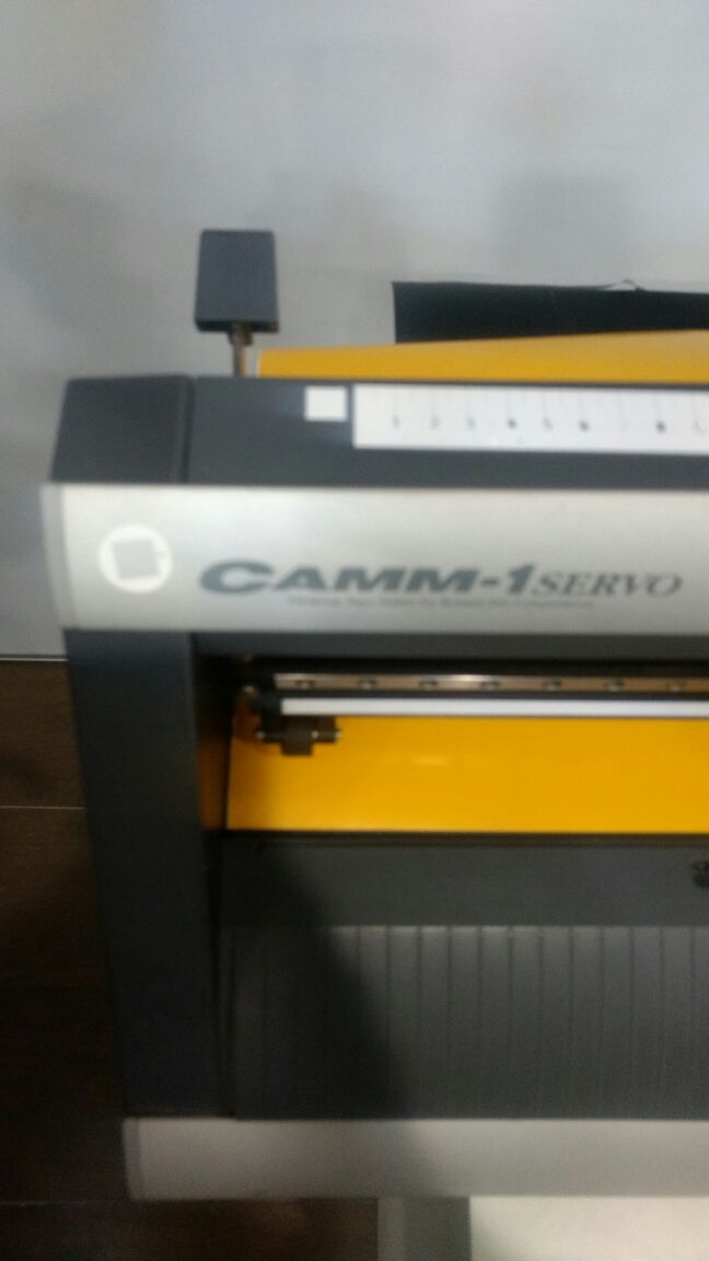
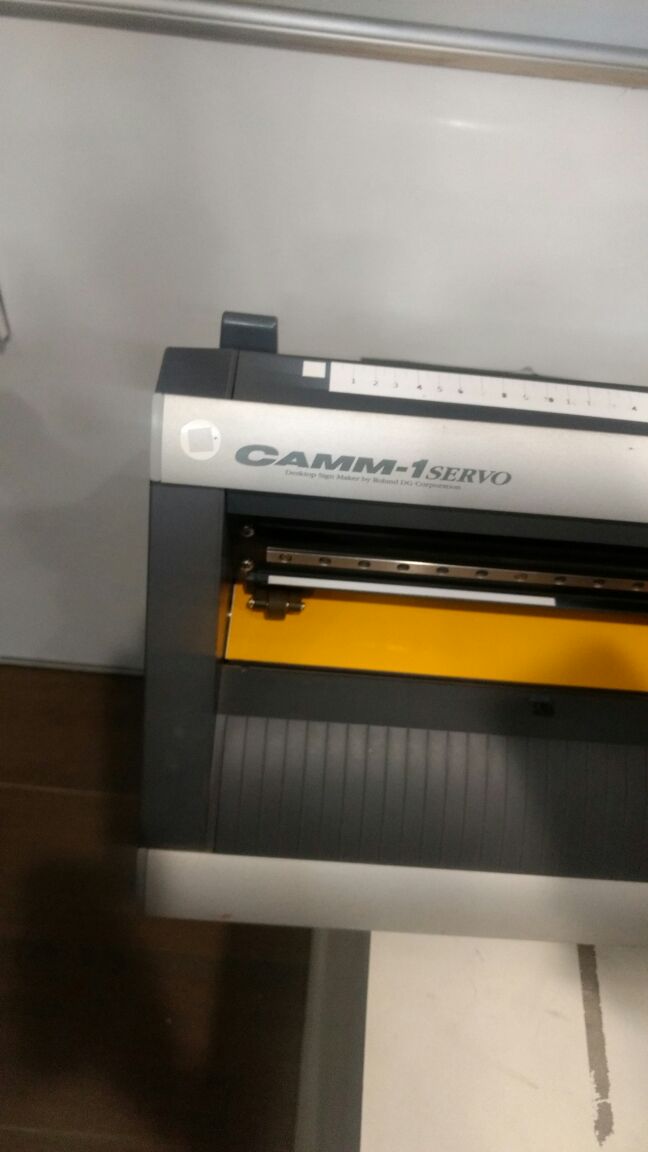
GX-24 Vinyl Cutter is the desktop vinyl cutter with working area of 700 mm wide vinyl. This uses a servo motor for speed and precision by using Roland CAMM-1 technology. There is a Test Cut button on the cutter which can verify the machines force before beginning of our job.
Machines used : Roland CAMM-1 GS-24 Desktop Cutter
To Start with I created a design of my name in Corel Draw. Then to print with I did some modifications in my design :
Go to Objects then convert to curves then Select outline color black then select fill color white.
How to use:
(1) The handle was up while I was loading the vinyl.
(2) I put the handle down after inserting the sheet of vinyl.
(3) Adjust the cutting force (GF - Gravitational Force) using the panel attached on the machine.
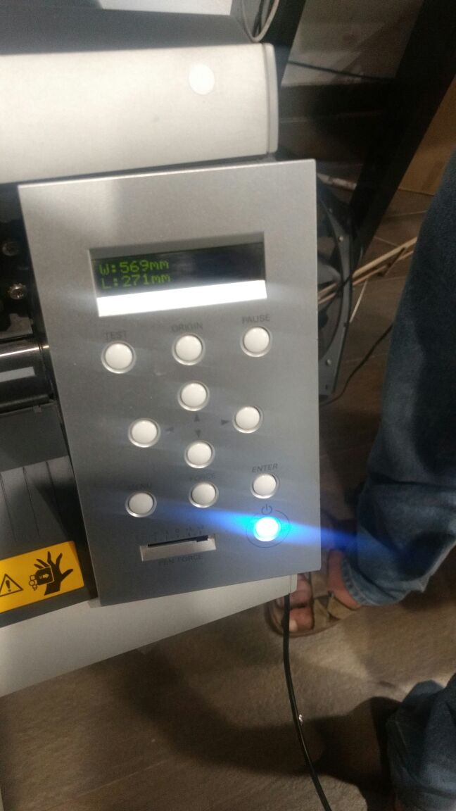
The main important point of starting the whole process is the measuring the size of the material which will be working on. Entering proper size of the Vinyl is necessary to align the designed graphics properly on the available/usable vinyl area to reduce the wastage.
Designing:
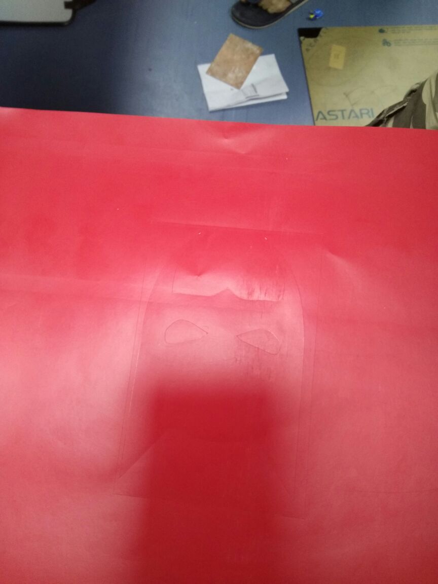
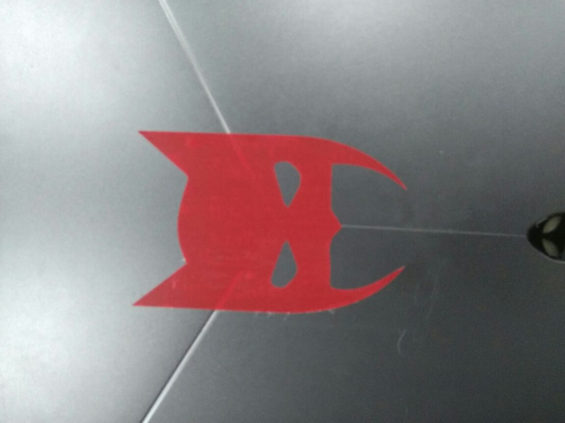
I imported the design of batman and then I used the trace command to trace the outline border. After the border is traced I selected the hairline option which make the border only visible. Since that the input for the vinyl cutter.
.png)
.png)
.png)
Cutting force : 100
After issuing the print ctrl + p in the dialogue box presented select the vinyl cutter from the list and edit the preferences according to sizing of the vinyl sheet loaded there's one more option to read the size of the vinyl sheet directly from the GX-24 for the same Get from printer.
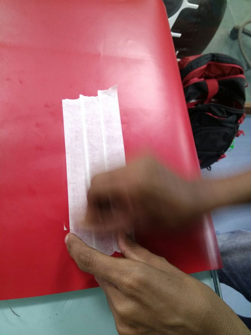
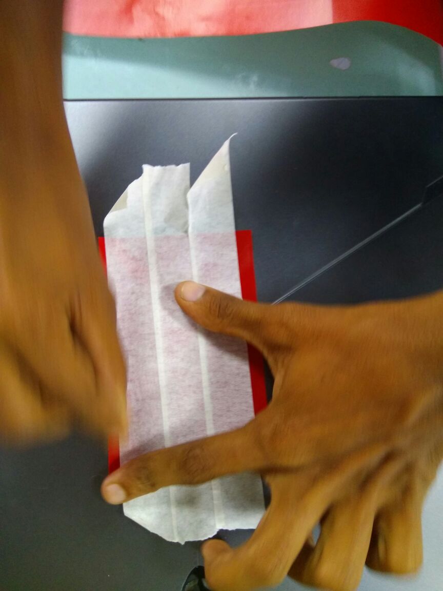
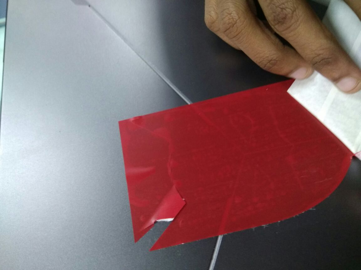
Had to tear off the final output with the cellotape. And Applied that cellotape on my laptop. After that using Tweezer I removed the unwanted parts. Here is the final output :