

Later, I added also Ø4 mm inlet and Ø2 mm air vent channels to my
model. Also, zero XY coordinates must be located at top of
workpiece and in one corner, as +Z axis up. Both operations used
250 mm per minute feed rate and 6000 revolutions per minute
spindle speed. Final check was that I use millimeter units.
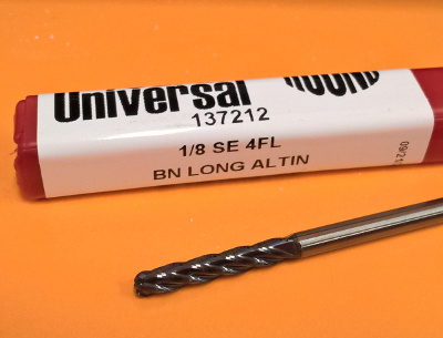
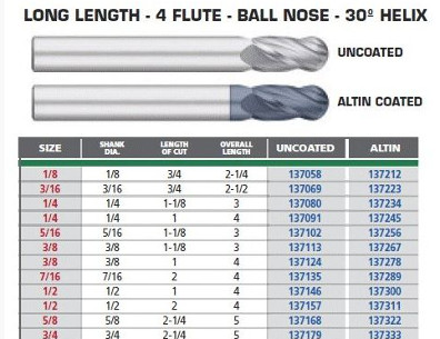
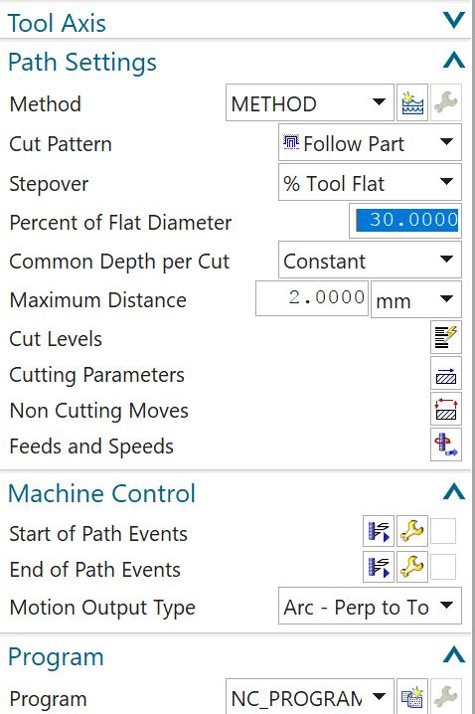
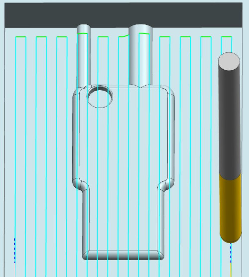
I made fist cavity mill operation to a Mdf -board by ball head bit, Ø3.18 mm. I used our CNC router machine Excitech E2-1325 for milling.
I inspected results and I changed my milling parameters. The bit will be the same ball head Ø3.18 mm. I lifted up the cavities to minimize milling time and material usage. Now the size is 50 x 35 x 8 mm (WxHxD). Also, I limited stepover to 30% instead of 50%, Depth per cut I set to 2 mm and minimum ramp length to 20%.

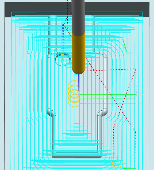
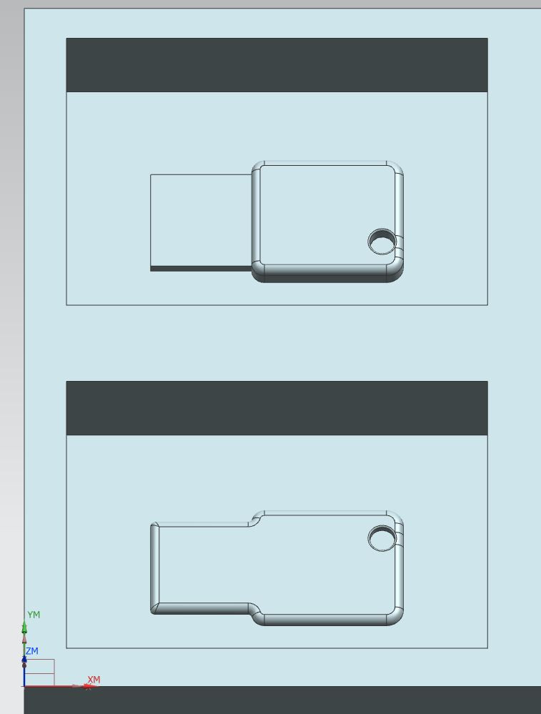
Finally, I read some documentation of NX11 use. And. I changed my
plan again. I planned rough mill by square head bit, Ø3.18 mm, but
I used finish dimensions. The operation was cavity mill as
earlier. Therefore, I got final dimensions to my mould as much as
possible. Percent of flat diameter was 50% and maximum depth
step 2 mm. Then, the second operation used ball head bit, Ø3.18 mm
and I only finalized rounded details. Method was area milling and
maximum scallop height 0.02 mm.


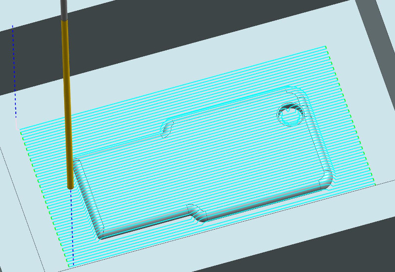
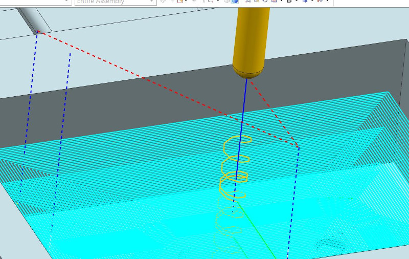
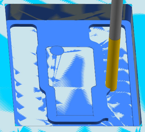
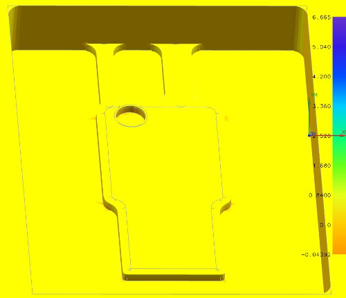
I found also new properties of NX11 CAM. If I select 3D Dynamic instead of Replay, I can see dynamically the milling process and finally non-milled material by color codes.
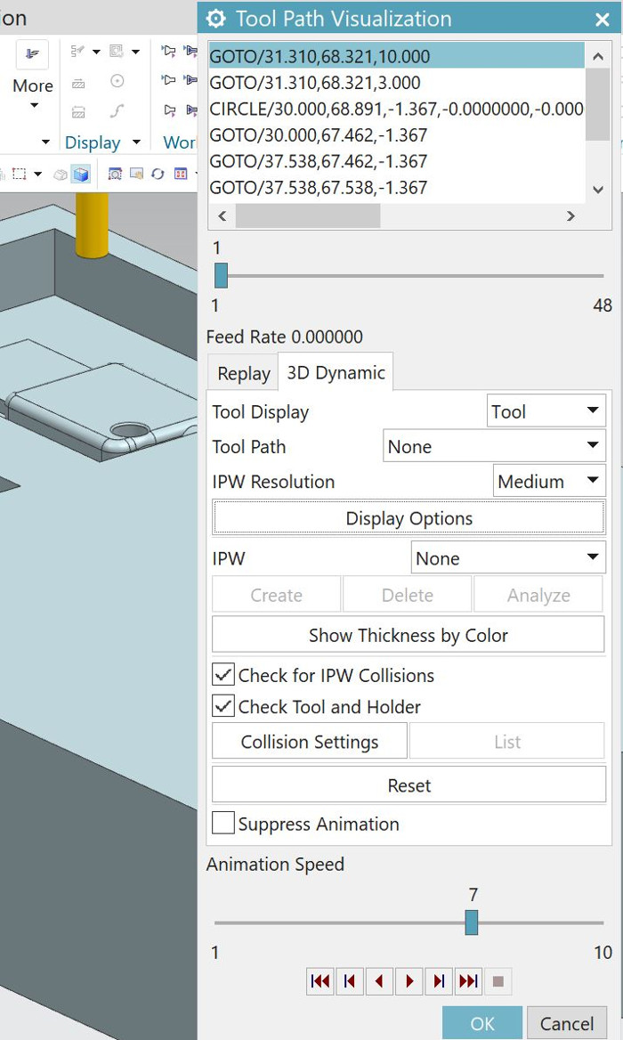
Blue color shows rest material I must mill out. Yellow color
shows material I cannot mill out by this operation and settings.
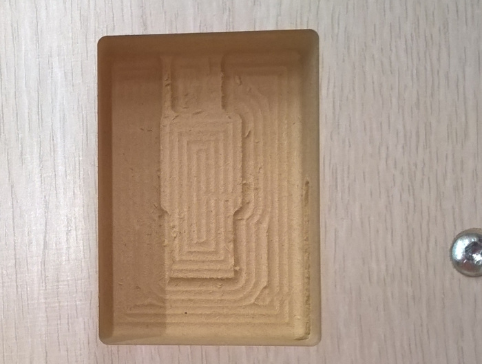
Again, I used our CNC router machine Eidtech E2-1325 for milling. And, I used MDF as mould material again. It is cheap and milling quality interested me.
Then, Ivan and Jari helped me in casting practice. I needed a cup, mix stick, gloves and many more. The liquid rubber I used was OOMOO®25 Tin cure silicone rubber, which had a 15 min pot life and 75 min cure time. The two components have one-to-one by volume mix ratio and I used vacuum degassing and release agent. The liquid plastic was Smooth-Cast®310, which had a pot life of 15-20 min and cure time of 3-4 hours. It is two components have also one-to-one by volume mix ratio and didn't require vacuum degassing.
Here is my first result, a dummy
test casting. It showed my mould works. It had some debris
from Mdf board.

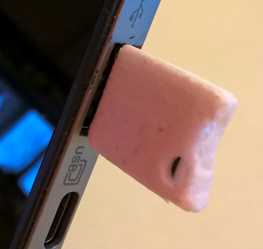
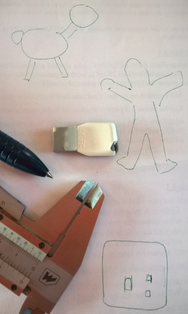
The second cast included also my
memory stick. I placed it inside the mould by tiny part of
paper taped in bottom of the memory stick. Also, I used two
sided tape for securing of contacts and it's correct location
inside mould. Finally,
my memory stick fits and works!
My NX CAD file is here: 3D model.
This also in DXF format is here: 3D
model.
And in stl format: FABmoldstick21.stl.
Ø4 mm inlet and Ø2 mm air vent channels worked well, but next
time I do conical inlet. It helps filling the mould.
I filled the mould contacts of the memory stick down and I see
the stick lifted up a bit, about 1 mm. The Ø3.5 mm hole I designed
as thru hole is as blind one.
Also, I wondered minor grooves on the mould. They copied also to
my part. They are parallel and done when finalized my mould. They
exist due to incorrect zeroing of the mill bit length. Our
calibrator of the router Z axis needs calibration itself.
Earlier during assignment 7 I documented that I needed to edit
NX11 postprosessed G-code before use it in our router. Here I
found I can use code without editing.
MDF is good mould material.