This week we the assignment was to build the mechanical aspect of a machine as a group. This is our group page. the group members include:
Felicity Mecha
Ernest Kimani
Derrik Mugasia
Our Concept
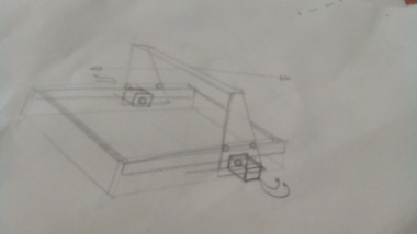
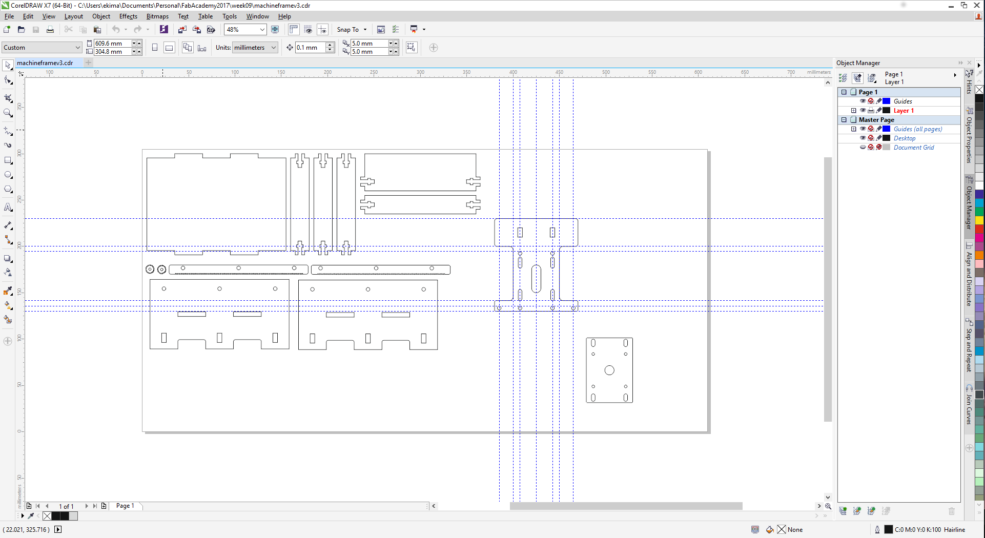
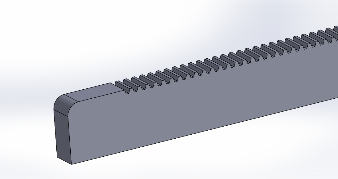
Our idea was to build a mini cnc router with a working area of 10cm by 10cm. the mechanism used to move the x,y and z axes is the rack and pinion mechanism. The material to build the body structure is acrylic(6mm)
sketch
Division of tasks
We all got together and divided the work into tasks. below is how we assigned the different tasks
Task
Person assigned
Resources used
Design of rack and pinion
Derrik Mugasia
corel draw, laser cutter
3D modelling
Derrik Mugasia
solidworks
Design of stand
Ernest Kimani
corel draw, laser cutter
Design of gantry
Felicity Mecha
Inkscape, laser cutter
Documentation
Felicity Mecha
sublime text
fabrication
Ernest Kimani
laser cutter, 3d printer
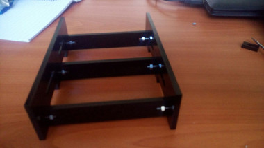
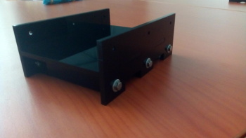
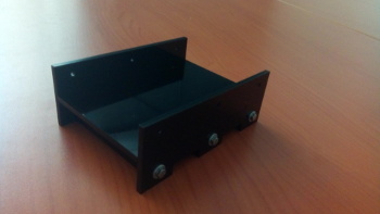
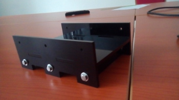
The base
base
base
base
Other fabricated parts
Parts
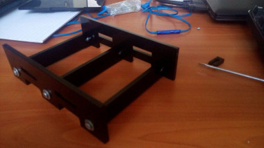
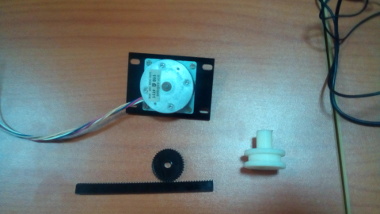
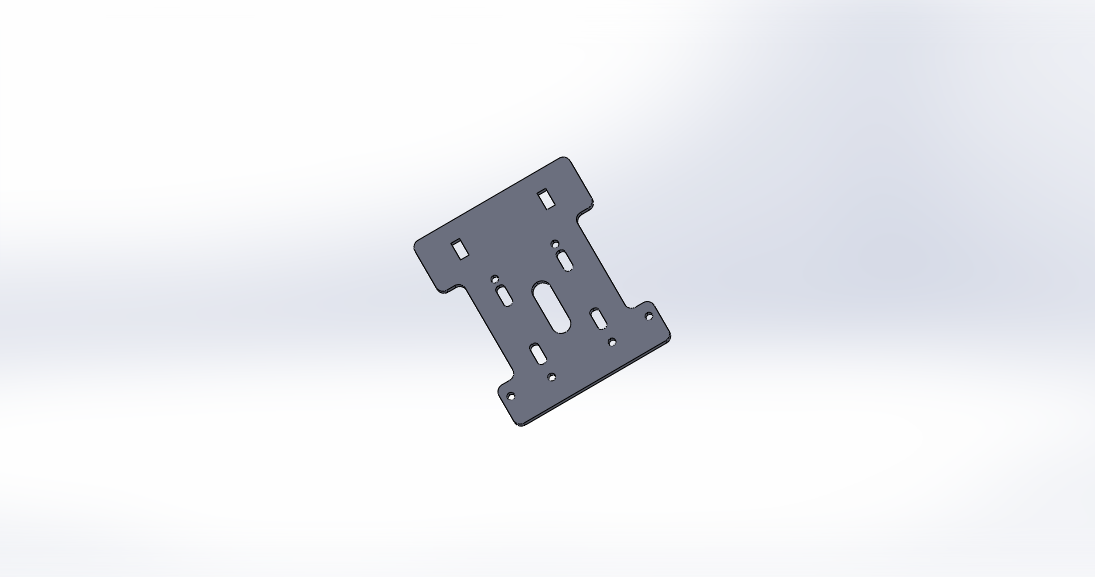
The gantry
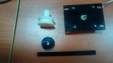
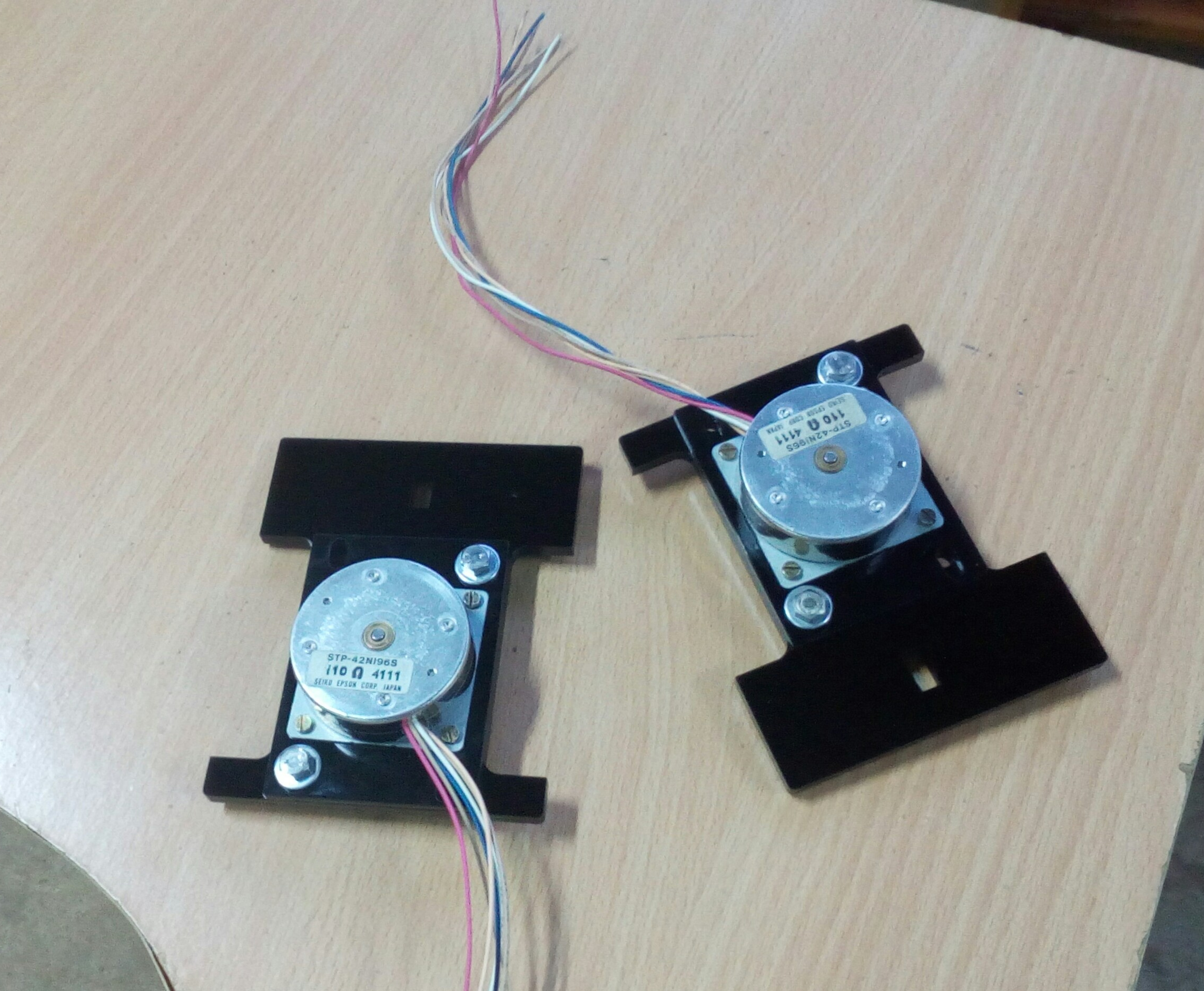
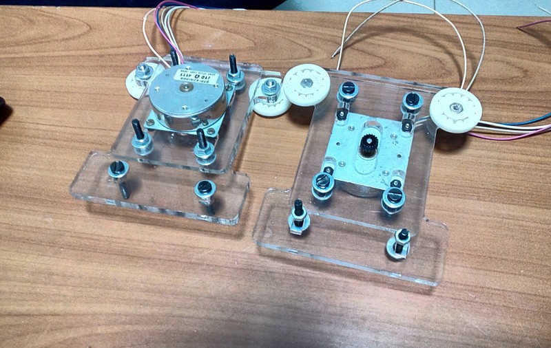
the gantry was designed in such a way as to hold small motors using screws as shown below
Motor holders
assembly
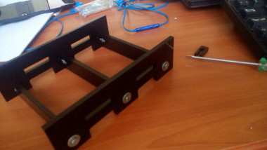
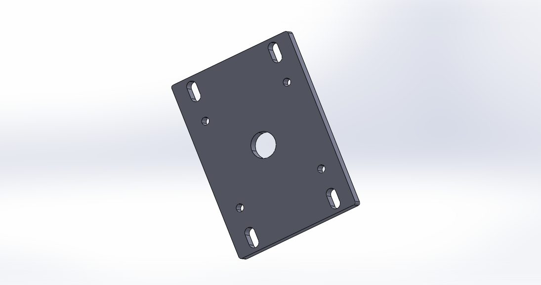
Modifying the design.
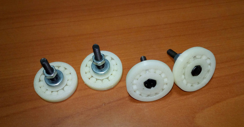
The design proved to have some design issues since the gantry swivelled unnecessarily during movement hence the need for revision the following is the modified design. We also incorporeted ball bearings that were to enable the gantry to be stable and not to swivel
Modified design
ball bearings
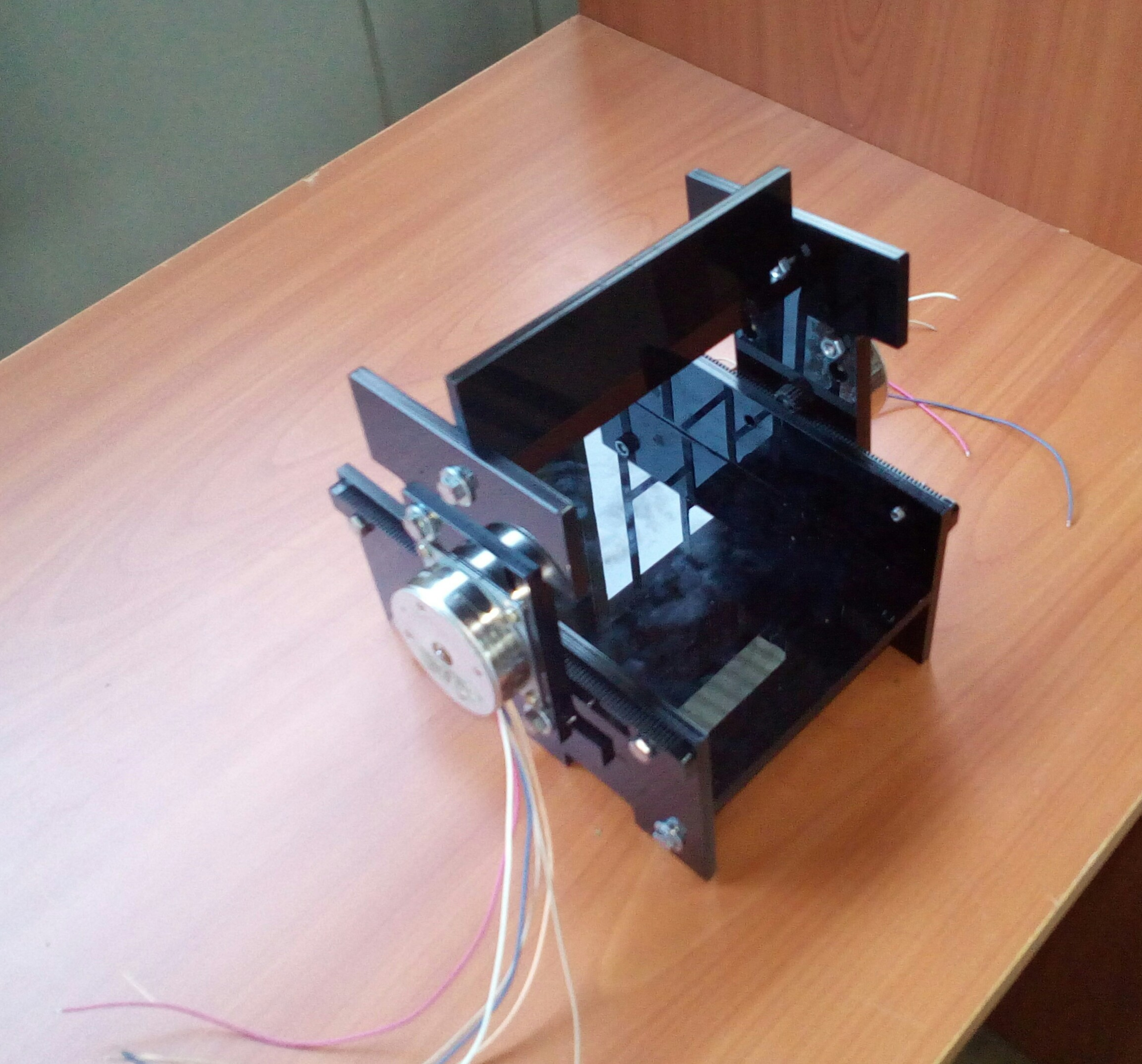
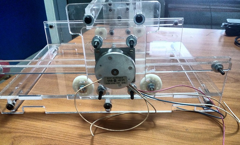
The new gantry assembled is shown below
Modified gantry design
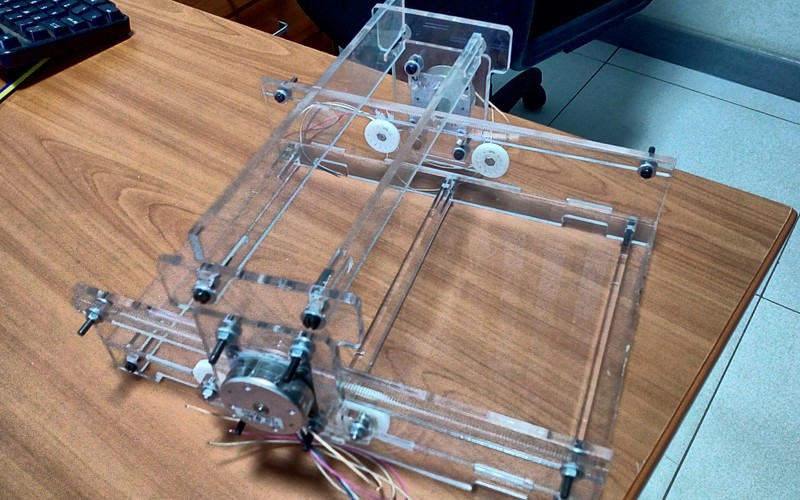
Finallly we assembled the machine using bolts and screws and the result was pretty satisfactory
assembled design
Assembled
3D Models
rack and pinion
gantry side
motor holder
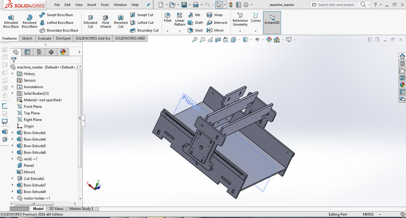
full assembly
3D model(solidworks)
<
The electronics
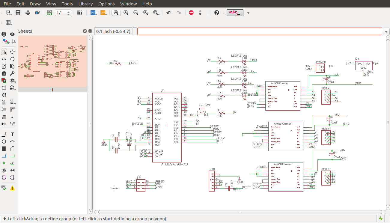
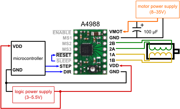
For the electronics we opted for Pololu moter drivers and a custom designed circuit board that is based on an Atmega 328p microcontroller. The design was made on eagle as shown. Since sonme routes were difficult to make on the pcb the board was made as two sided with the intention of using jumpers .
Eagle schematic
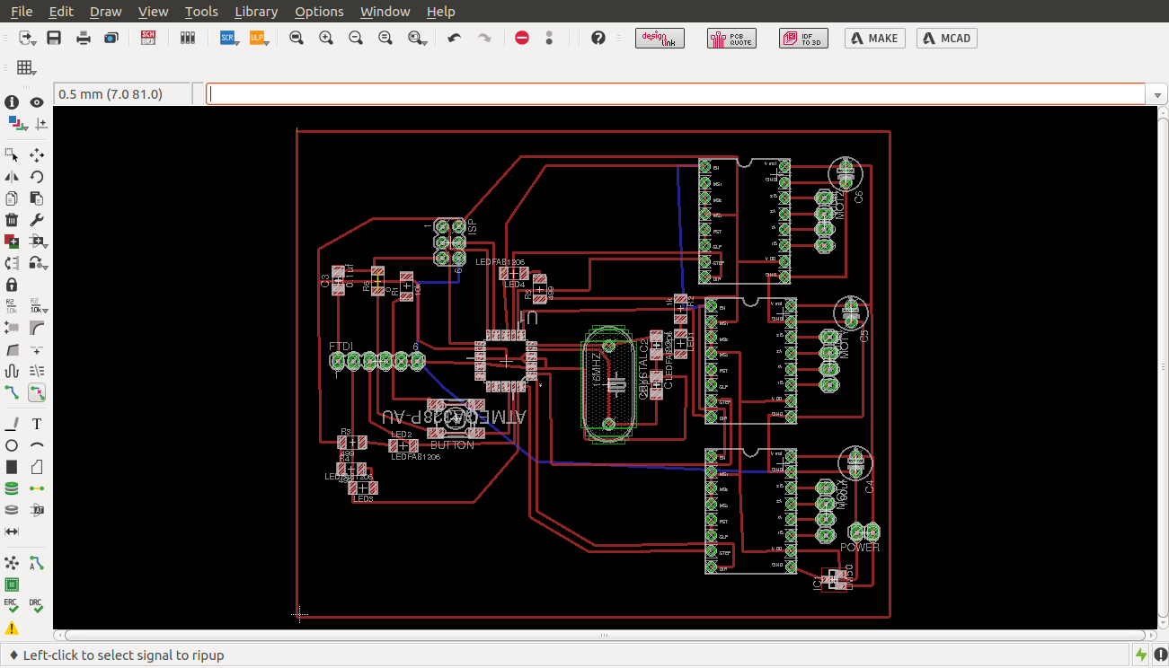
Eagle board
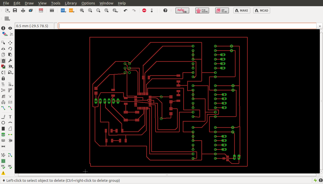
from the board we were able to extract the traces as shown
Eagle board
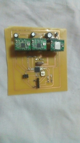
After etching and stuffing the board it came out as shown
fabbed board
Testing the electronics
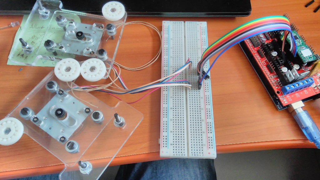
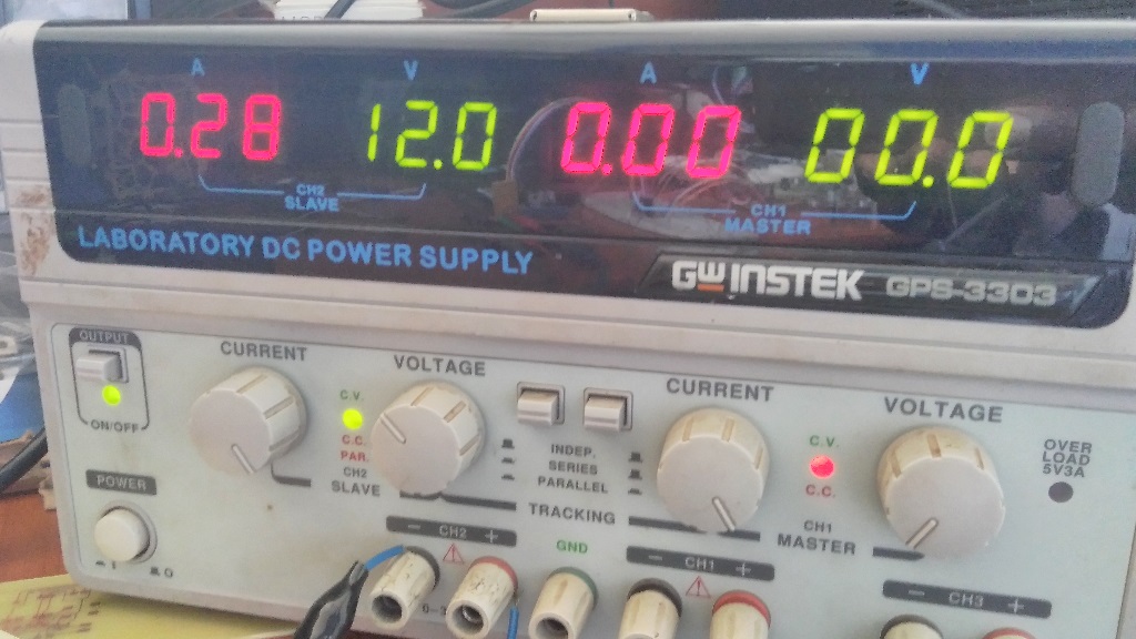
To begin with, we tested the Pololu - A4988 stepper motor drivers that we were going to use together with the motors by applying 12volts to the RAMPS 1.4
Polulu driver circuit
motors
power supply
Using the test code from reprap wiki page to test the movement of the motors and everything ran well.
Automation
Aftter comprehensive research to find an efficient way to command a machine, communicate to it as you get feedback through an interface.
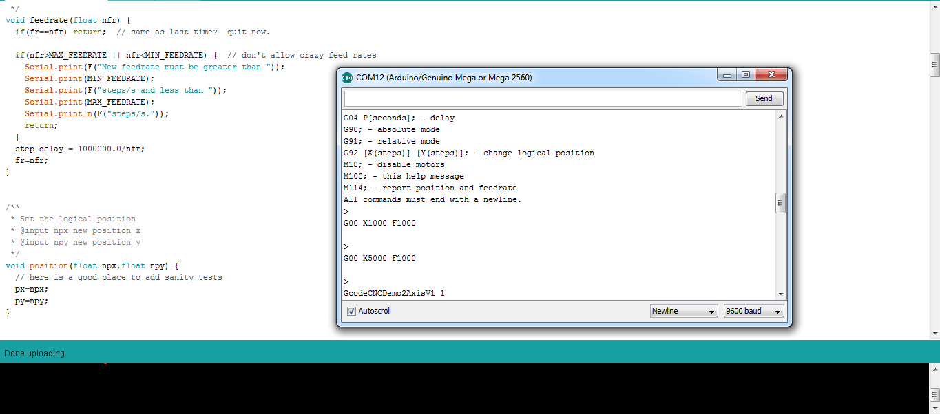
we decided to employ a G-code interpreter right on the control board, and communicate to it through serial interface.
Marlin Firmware is a beautiful open saurce firmware done especially for 3D printers. I went through it and atched afew videos to appreciate the impact of that platform.
Makelangelo software is also another open source code that provides a UI written in Java, which can be used to load images, process them and print them on the robot over a serial connection.
Eventually we found aG-code Interpreter by Marginally Clever.
which was edited and used to communicate to the motors through the serial monitor.
The video
To view a slide and video, Follow the links below
Below is a you tube video of the working machine
Problems faced
swiveling of the y-axis: The y axis was not stable for the first design but this was rectified in the second design using bearings
The first design was too small: For the first design the bed was too small and the y axis too narrow for us to adequately design a z-axis. We therefore had to increase the dimensions.
Future developments
The machine will be improved in precision and will be used in the lab to mill boards. we will also share the design with other labs for further development and use. The machine can also be made bigger to mill bigger objects such as wood. it can also be made stronger so that it can mill harder objects such as aluminium. We would also want to custom make a user interface for the machine.