Here's my updated video with worind code with my arduino shield + OLED
Below the video that I used in Neil's presentation. Presentation went well. Neil's suggestion was to fill with silicone the mold.
I did for my Week #17 a Gantt diagram in order to plan my process and project development.

After surfing Arduino's LCDs tutorialsI started to look for specific codes that could be useful as starting point.
I first looked up some projects for cronometers and clocks. this one was the more clear one.

Waiting until having every needed piece to start programming would have been stupid and time-wasting. So I tested the code with an Arduino UNO board and a LCD keypald shield with buttons that I bought for my thenth week.
No cronometer yet, just basic setup. The challenge of dong a cronometer is setting the hours minutes and seconds, meaning the correspondance btwn all of them and "milliseconds". Why? Because the millis() function does measures time in milliseconds and i needed to do the conversion.
This I the way I did it buy I am welcome to any
Check this link for another tutorial that helped to sort out how timer are setted up in Arduino. And here's further infoon the millis function.Millis funcion is a MUST for cronometers and timmers. What i basically does is start counting time when the prgram/device starts running. This is why you will see in my code lalala = millis - "something" since time has started running before you wanted him to run and therefore a sustraction is neede.. More on the millis function here.
First tests were mainly about layout (where each information will be located in the display, which I did in the void/setup function) and making the cronometer work. Since my test display has buttons I did no t worry about that, al least not for now.
Yes, the LCD+arduino are strategically laying in a banana>
So far so good. Timmer works (increasing). I need now to develop a countdown one and relate this to pins/buttons and functions.There's also some tidyng up work I am developing, see the eady after the seconds? That's because I did not "lcd.clear()" the previous welcoming text.
Here's an error in my coronometer.Already sorted this out I had set the cursor in the wrong place and the secs overlaped the":".you really need to be carefull with setting the cursor correctly in lcds. What I am coind now (you will be able to see below is creating variables x,y and setting everything in relation to that position). Much better that countgin spaces every time.
Couldn't be THAT easy. My screen must display 2 timmers simoultaneously. One of them needs to be a timmer (time icreasing) and the other a countdown one (time decreasing). Thanks to Andrew Mascolo who did this lovely countdown timmer library which you can download here.
This brought other issues as thisonethat's about issues about having two loops (not possible darling)
This meanig the following error poped up

I have so many printscreens with errors ans pop ups I don't even remember thi one. Probably a variable that
I finally did not have to use a countdown cronometer, still good to test stuff.
I had to choose between analog and digital pins when starting to code my device. Digital was my choice. Why? Well, because coding looked easier and more staightforward meanig inly HIGH and LOW options are possible.
I did find some basic cronometer codes using analog pins thought. I was not so comfortable wokring with values shown below.
I changed my display choice for a prettier one. Meaning a new bunch of code had to be arranged. Many, many adafruit tutorials to be found in their website.
I fisrt started with basic graphic tests which was pretty fast and exiting, I even danced. I then moved into characters function. OLEDs are a pixel based screen and there was no way I would have print text pixel by pixel so..libraries! Most usefull ones: Adafruit GXFand ST7735 and SSD1306.
My Screen is much smaller, can display color, different text sizes and bitmaps. Plus this awesome websitehas it all.
Another interesting function on programming I used was the switch case one. Why? Because My scheme worked pretty good with it since many deployable options can comeout depending on the pressed button.
So my code look pretty easy and straight forward after this, below the different cases loop:
More info on this particular function here.
Getting the right layout was a pain since I had to change from case-based lcd screen to pixel based OLED. Below some samples.
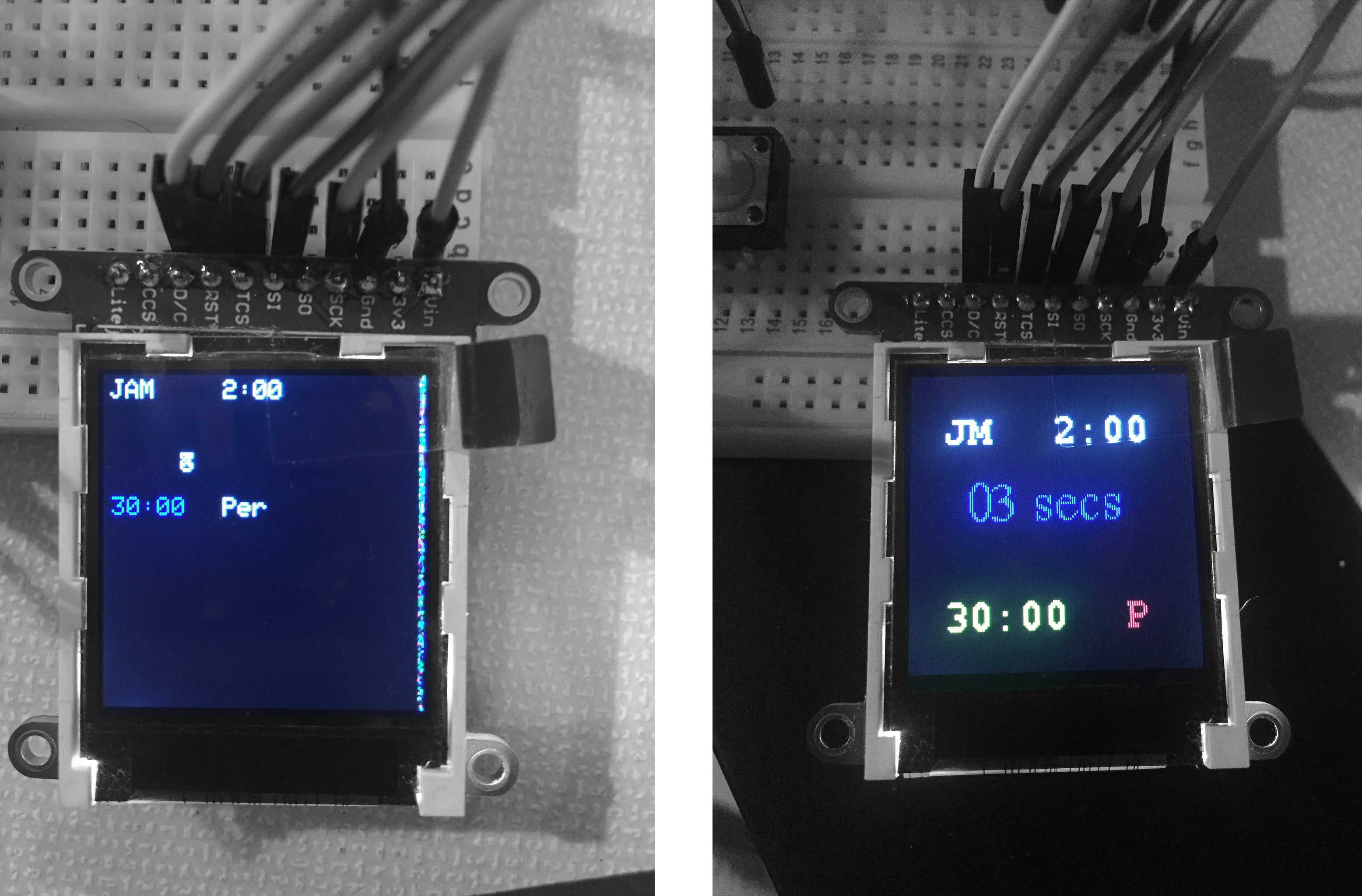
What was not easy about changing was teh fact that LCD uses cases and adafruit uses pixels so a lot of overlapping needed to be sorted out.
overlapping was not the only problem. The command lcd. clr does not work in oled, and sometimes you dont want to clr de whole screen What I did with overlapping and
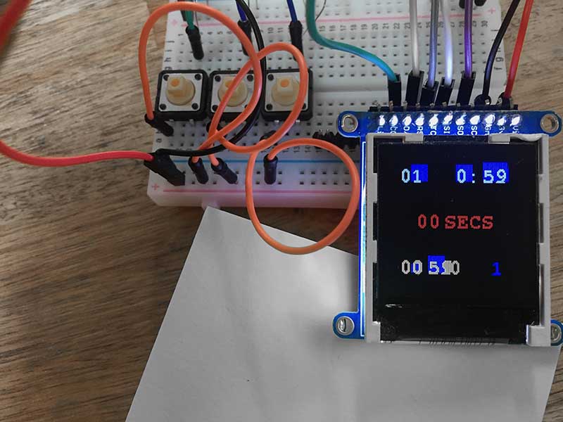
I re-wrote my code the last hour. Thanks to Pablo and his knack for code. I made it tidier, smaller and more clear. Just to have a glimpse of it: since I did not needed the hours to be displayed in my cronometer I reduced it to (see first two lines of code):
I struggle to get the desired layout and did some serial monitor tests to see if the code itself was ok.
I has issues with the passage from milliseconds (millis() function in Arduino to minutes and seconds. I did change the way to define a cronometer so I am not sure exactly why it did not work in the first place. My guess is it had to do with the type of variable since I wasn'y using a unsigned long one but a int one and millis values are quite big.
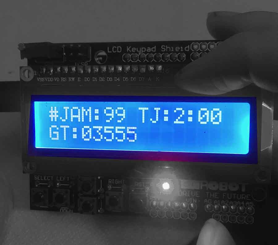
It AAAAAAAL works meaning:
welcome message: ok
General time increases except if paused (bottom left)
Jam time (top right) increases only if start button is selected and is resetted to 0:00 if it reaches 2 minutes.
Jam Number (top left) automatically adds up when a new Jam starts
Period automatically changes to 2 if needed. (bottom right)
Start, Pause and Reset buttons work according to the dirrent states created and needed.
No text or numbers overlapping (I can't believe I got here)
There's a weird Glitch in the Jam Numer (top left)
This was the basic wiring for the graphic test. My main needs here were to: create an andruino with min 9 working pins, 3 for my 3 buttons and 5 for the OLED display.
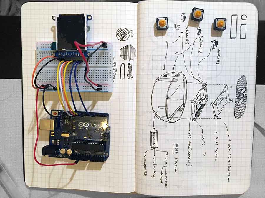
Below 3 needed buttons with their respective 1k resistors in a protoboard. How would I fit this into a home made arduino and make buttons to pressed from the outside of the spherical device? No clue yet.
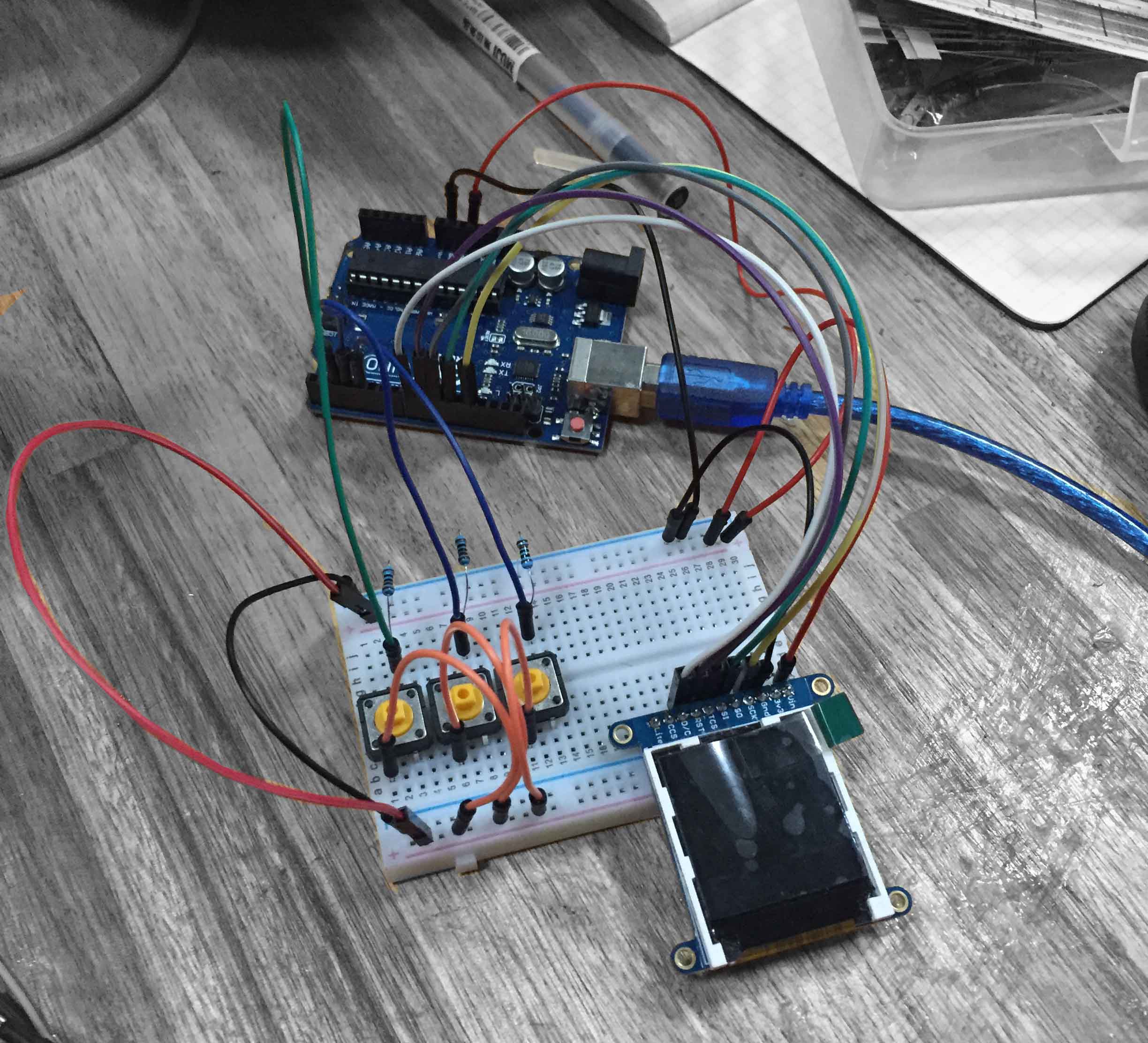
I will have to use drills to keep my device compact and make it fit into a sphere. See my sketch above.
pin testing above to make sure all buttons controll what they need to control. 3 buttons are for: 1 start/stop 2 for pause 3 for reset.
milling the first story of the board (yes, i will do a building)
if you take a closer look the crazy part if this is that stories are not always facing eachother what made the design as complicated as possible on earth.
Below the 3 parts of my sandwich board
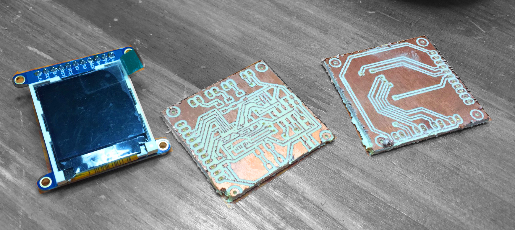
Doing one's own arduino is not as complicated as it looks like given the fact that there's a beautifully crafted website with all the needed information to mill, sold and build your own one. Problems started when I deciced to fit all in a small sphere meaning a 3 story pcb building:

Alvaro said this reminded him to 60s boards when components were too big to be ruface mounted and they layed out like this:

So I basically did 7 arduino test and manage to make a menage a trois of boards.
Testing the never ending solding:
Hard core stuff:
above my tripple story arduino + OLED shield.
I am still shocked about this 3 story board being programed:
Below the schematics and board of my voltage regulator. I know my screen has its own voltage regulator (see vin pin) but I still need one since I am using 2 3V batteires.
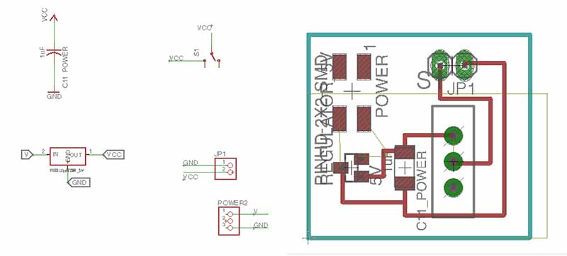
I fitted this as hidden as possible and connected a beautifully ugly switch since that was the only one available in our teeny tiny country.
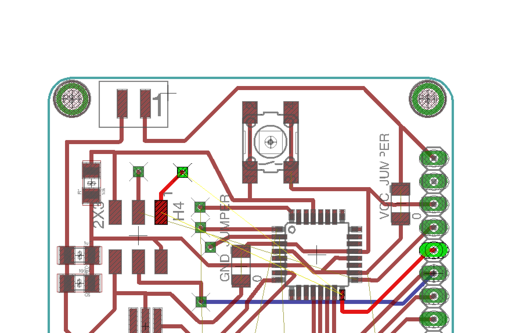
Even if my initial board worked I developed a second version of it. Why? Because the tripple story board was a pain and seemed to me unnecesary. Therefore I redesigned the arduino layout considering the whole surface of my sphere (device) and manage to get only an arduino + Shield (not a 3 story shield)
Components were exactly the same, the shchematic barely changed, only for a couple of jumpers, It was more of a layout (board) improvement rather that an electronics one, because (AGAIN) I was lucky it did work the first time. Plus I included the voltage regulator in the arduino to avoid having boards allover.
I evaluated several options for the case, its opening mechanism etc. I need to create a sphere (or two semispheres because the device can be opened in half since the screen is inside). Below a quick sneak peak fo the whole story of bachellors.
Thank you former student for your help even If I won't use it. What I wanted to do here is to create a mold for shaping acrylic.
This wasn't even a bachelor but a test I did to check if the sphere size worked OK with a human hand and MAINLY to see where to locate buttons.
What I do with my fingers in the above video is pressing the imaginary buttons to control the timmer. I then took the coordinate of each one to model the real thin in 3d.
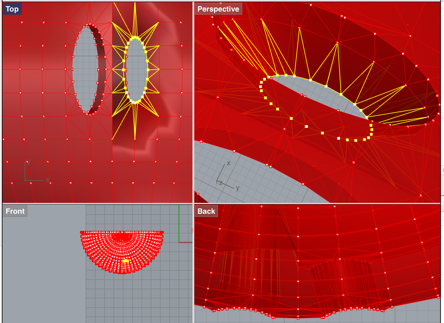
Modeling was pretty basic. A hollow sphere, a solid fill for the boards to be layed on an horizontal surface, holes for the buttons If you take a closer look at the internal edge of the sphere you will see that the section gets wither and thicker to support the acrylic.
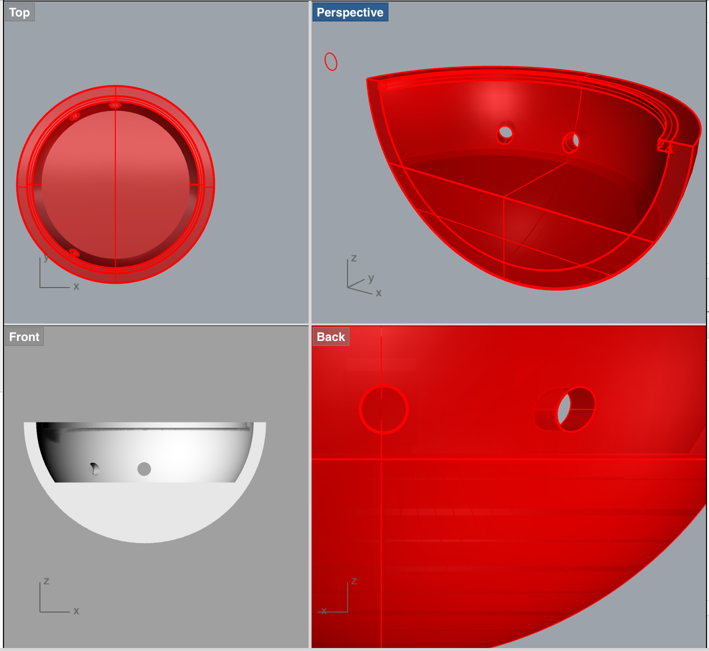
And the hole for hanging the jam timmer's into the ref's neck, like a hanging necklace cronometer.
And the winner is: always the last one. I will finally 3Dprint my sphere. Main challenges here are :1_the battery (how to remove/insert the batter and what kind of battery)2_How to open/close the device (Mato gave the great idea of magnets)3_How to hang the device on the ref's neck. Here's where 3D printed textile comes in (I really wanted to do something with textile and fashion after all).
Time to "stick" all the parts toghether. "Sticking" since I didn't actually stick ANYTHING. I know changing batteries and having a small pockets/trays that can be opened can sometimes be a pain and end up in a missing piece of the device.
You will notice the skin of the project is flexible and can be removed. I printed it in filaplex which is a plexible material and since it wraps the laser-cutted sphete It can easily be removed to change batteries, maybe the screen, clean the decive (only for OCD) etc.
Here's how the screen looks assemblied with a transparent acrylic on it. Neil's suggestion was to fill the halph sphere with silicone which I will gladly
The acrylic ring you see it's for fixing buttons. I am still looking for the right button to be. One hard part of this Is that for the final/sellable product It will be necessary a double skin. Maybe a more rigid one to keep the push solid and stable cause as you may have seen in the video it does not pushes properly everytime even if the codes work fine.
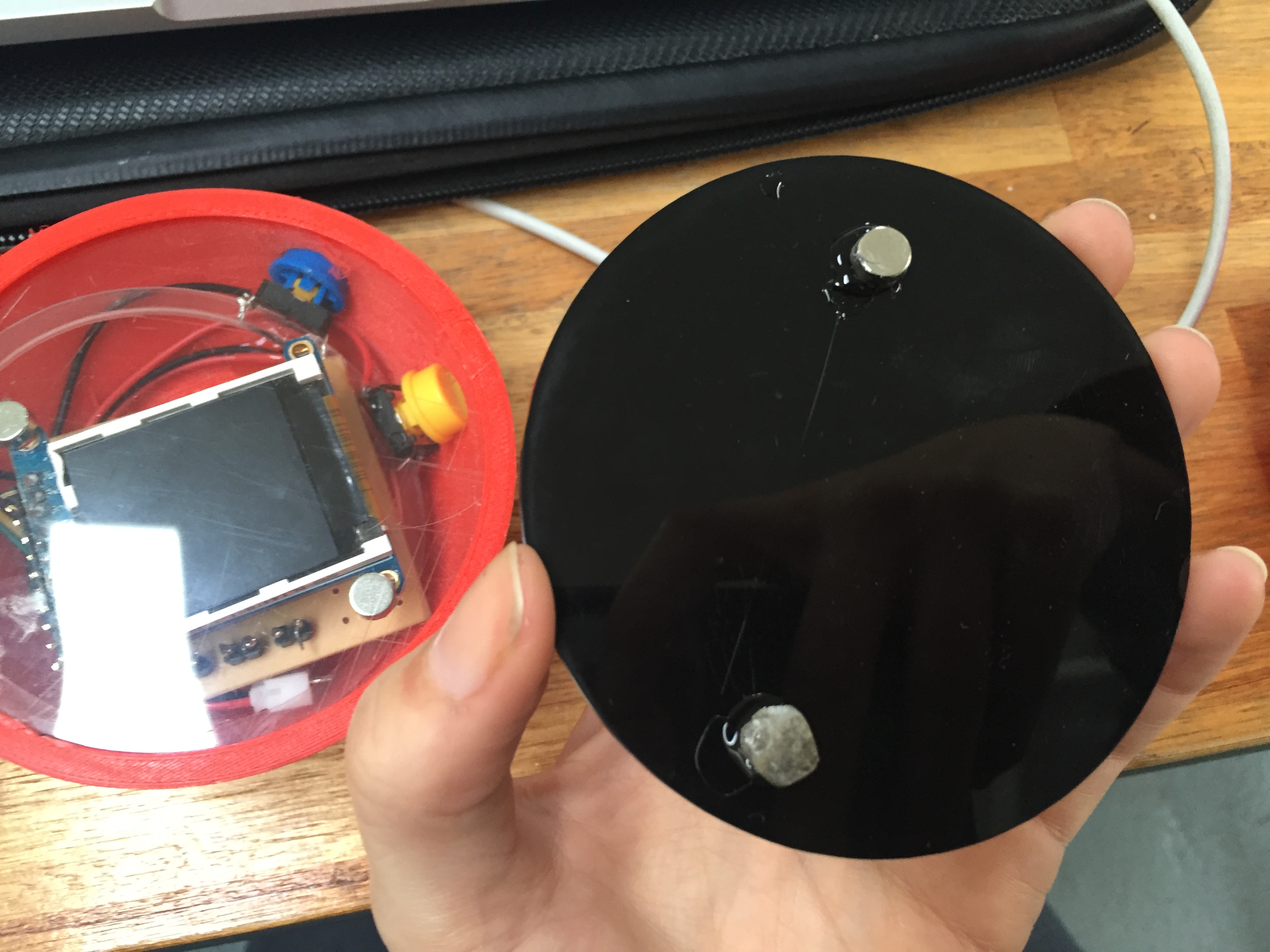
I have not mentioned this but I ve added magnets to close the device. See picture above.
Note: you can right click on the linked word and select download linked file.

Go backto the INDEX