1. Vinyl Cutting
With the vinyl cutting machine, you can both cut with a .SVG file image or a .PNG file image. I am going to use both to see the differences.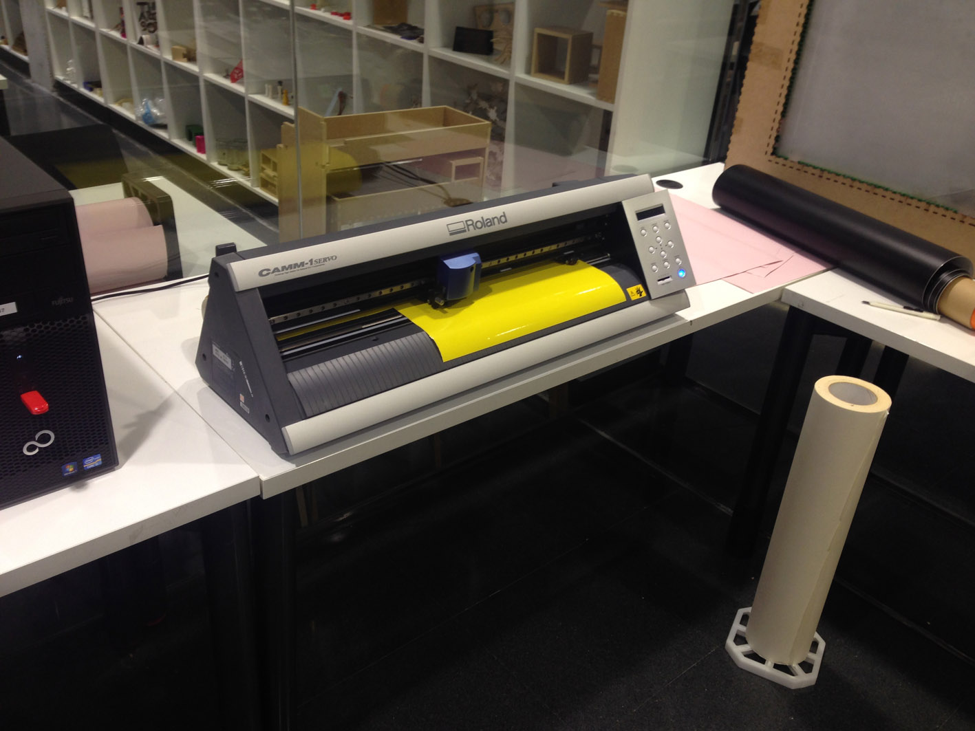
Using a .SVG file
A .SVG file is an image made out of vectors. What I did was to take an image from the internet, from a website called 'Animalia Life' (boton con DIRECCION:_ http://animalia-life.club/other/jaguar-face-black-and-white.html __), go into the gallery and pick the one that I like.The file that I have downloaded from the internet is a JPG file, and I need to convert it into .SVG file. Therefore, I open Adobe Illustrator and import the image:
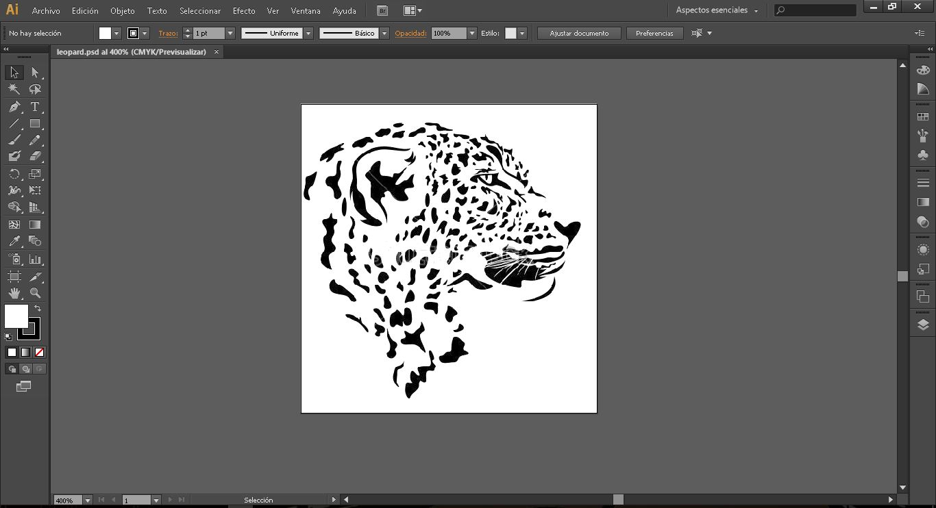
The tool I have used to convert the pixel to vector is called 'Trace Image' and select the 'Black and White Logo'. What it does is, it takes all the black pixels, converts them in a group that on its perimeter is closed with a vector. As there are lots of black spots, there are lots of closed vectors that are filled with black. Here is the image after being traced:
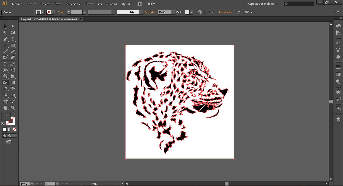
In red, all the red vectors that create the leopard figure.
Now I have my modified image and it's time to export it to SVG file and import it in fabmodules.
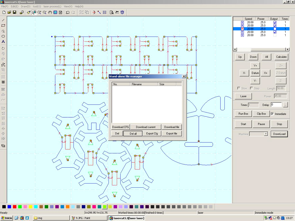
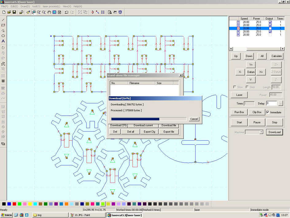
Turning the machine and the computer on. Open the cmd and enter './fabl modules' to start the connection between the machine and fabmodules. The next message appeared:
'listening to connections 127.0.0.1 on 12345'. --> Everything ready to start using the computer!
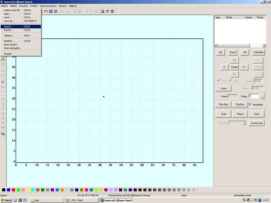
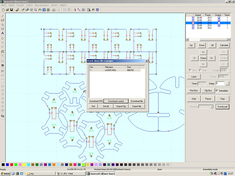
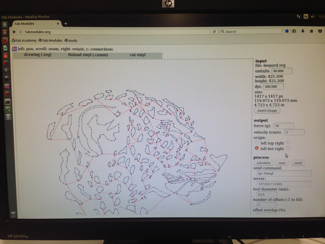
The next step is to import file in fabmodules in firefox:
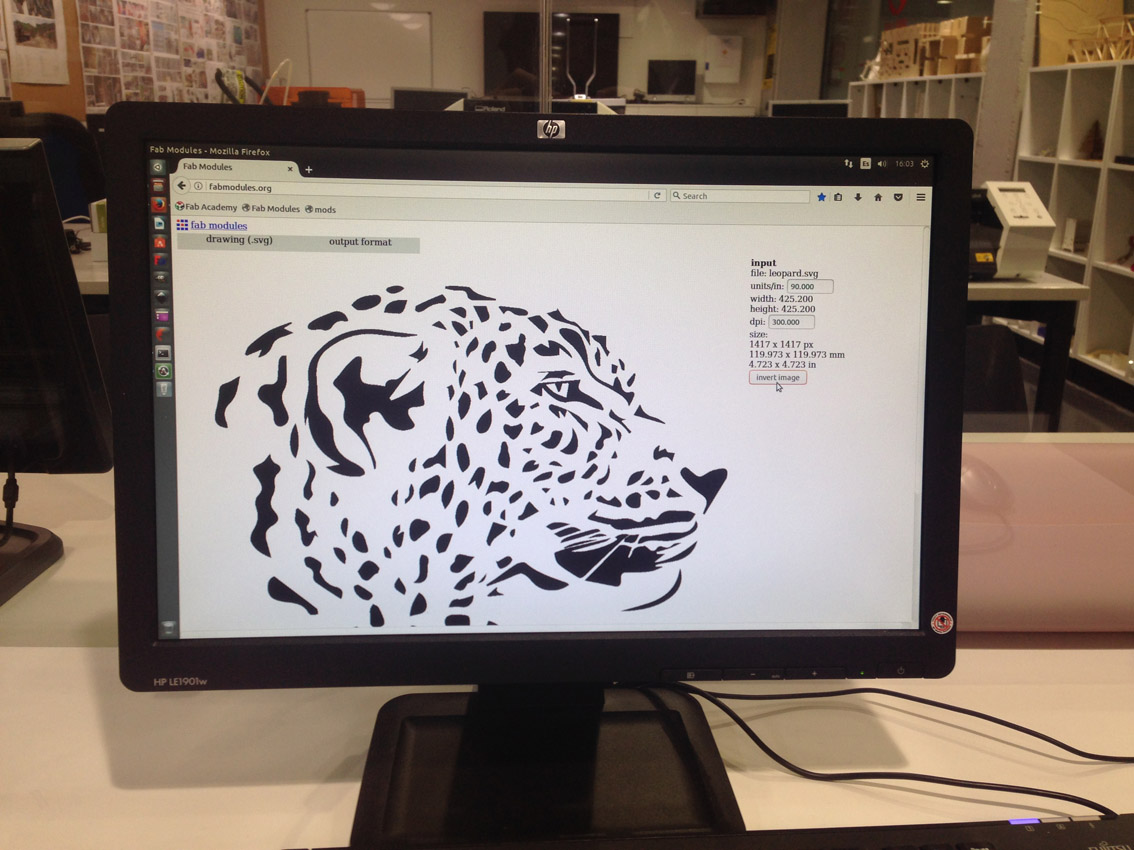
Input file: svg
output format: Roland vinyl
Process: cut vinyl
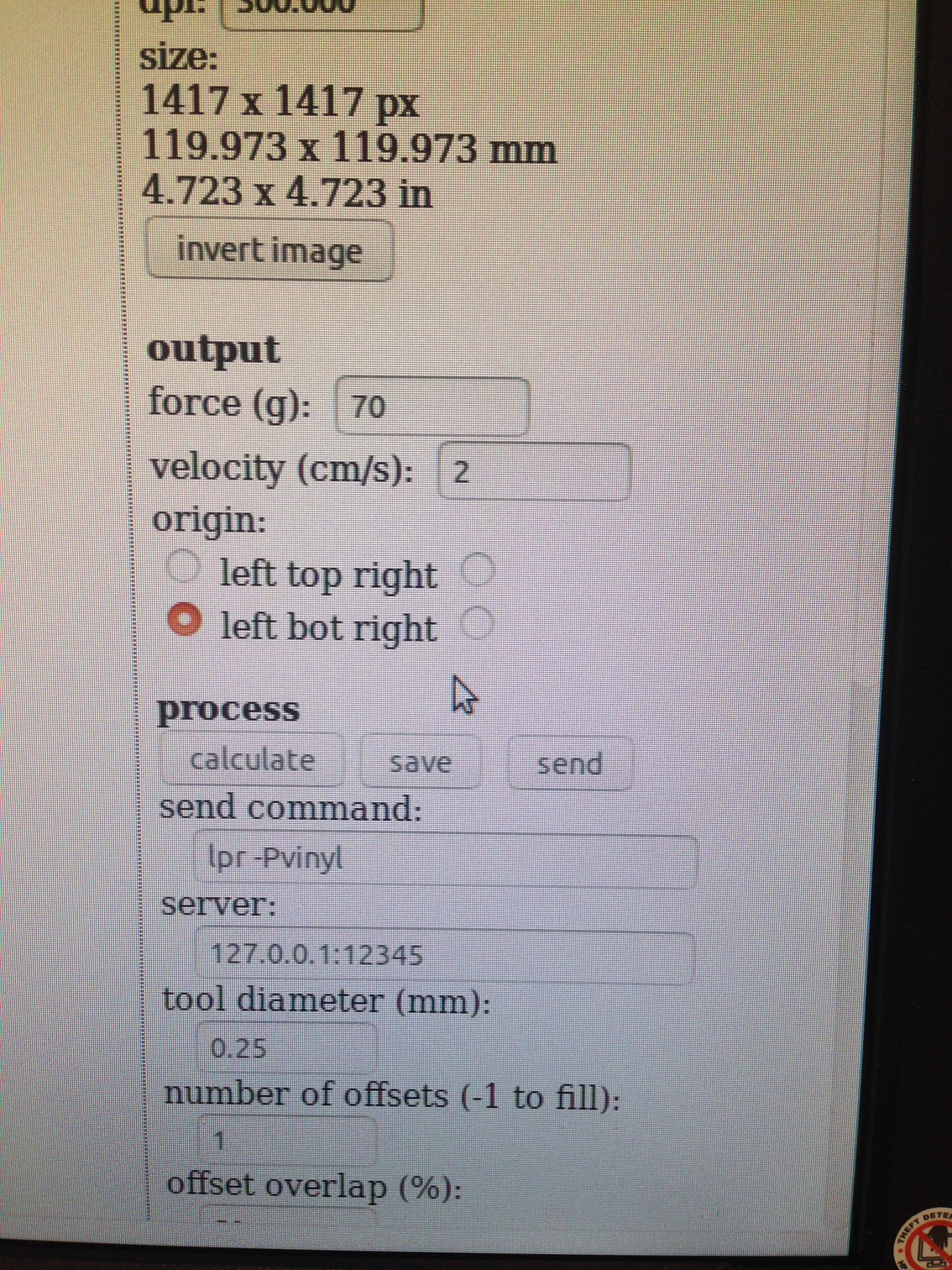
Properties:
-size of the image: 1417x1417 px with 300 dpi.
output:
-force: 70
-velocity: 2 cm/s
-origin: left bot right
-process:
-tool diameter: 0.25mm
-number of offsets: 1
-no offset overlap
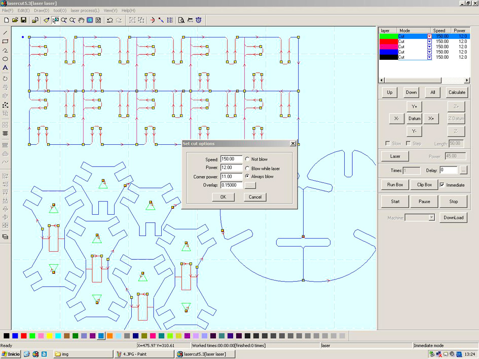
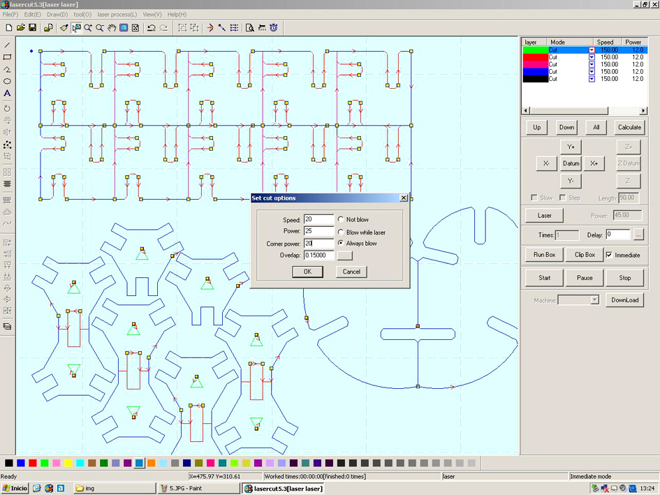
Before calculating the image, I need to adjust the force needed as always a test is needed before cutting.
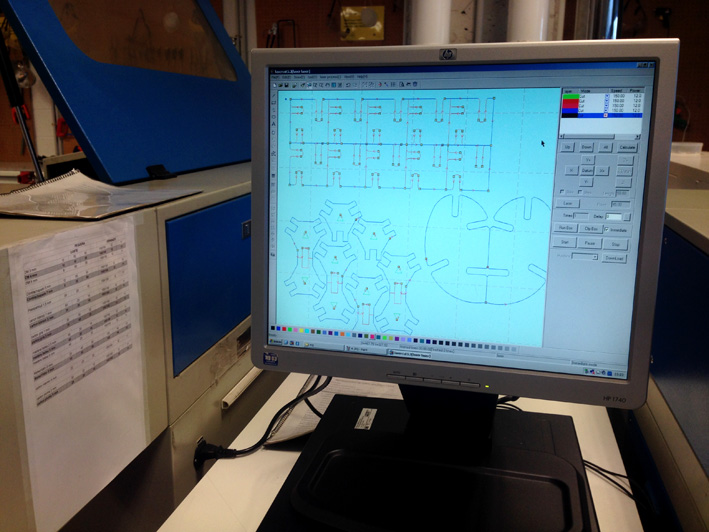
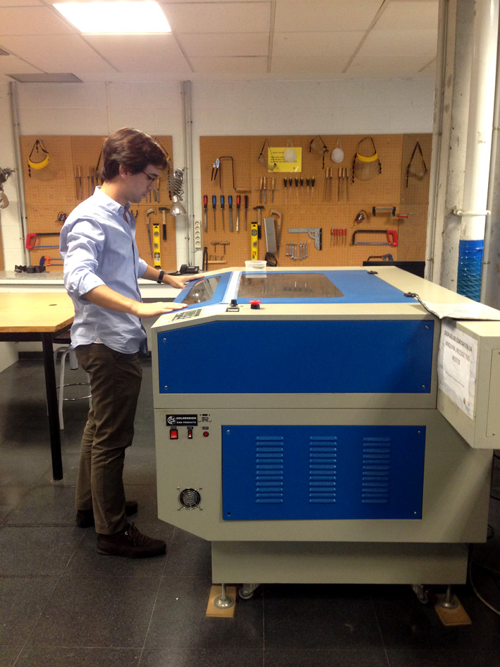
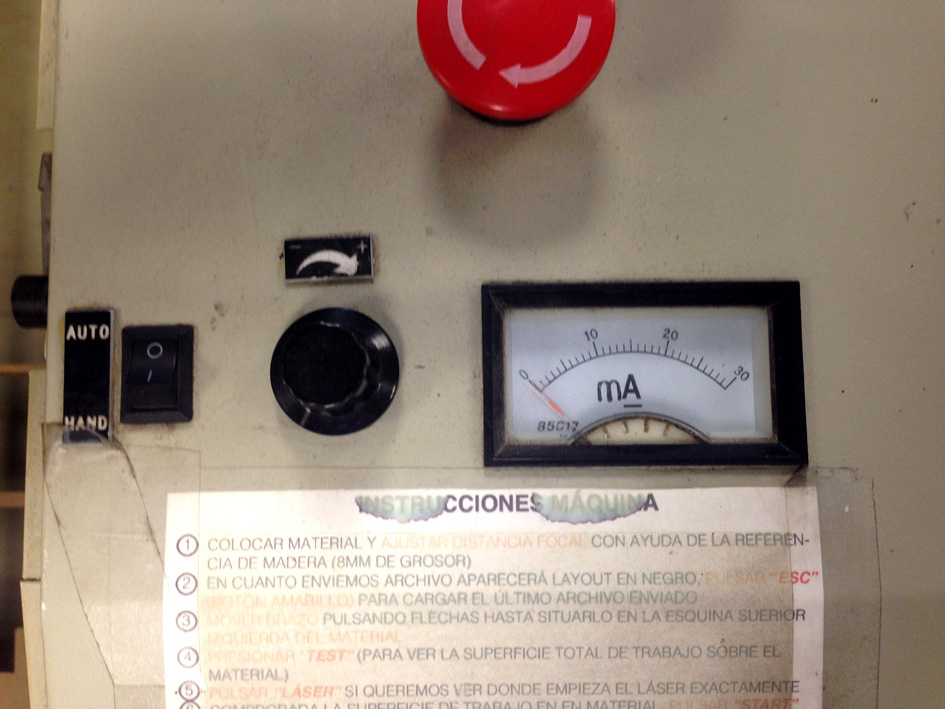
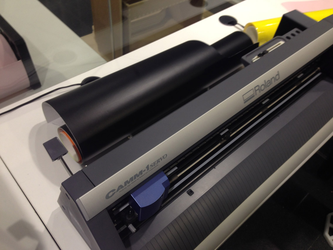
The Vinyl Cutting Machine
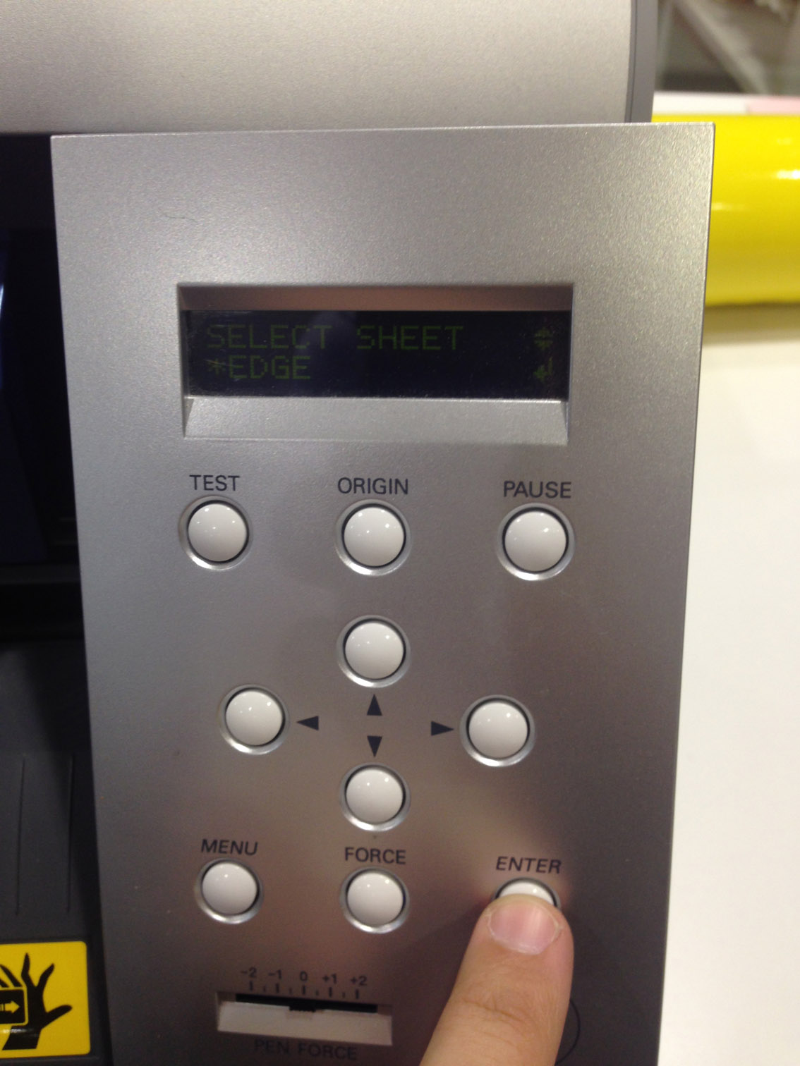
When turned on, I need to select what type of vinyl am I cutting: a piece or a roll.I select a roll (as it is a pink roll), and there are two options: select 'roll' or select 'edge'. I select edge, the one that cuts your file on the edge of the paper.
I align the vinyl and tighten it with the small rollers the machine has.
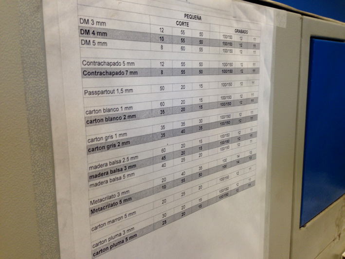
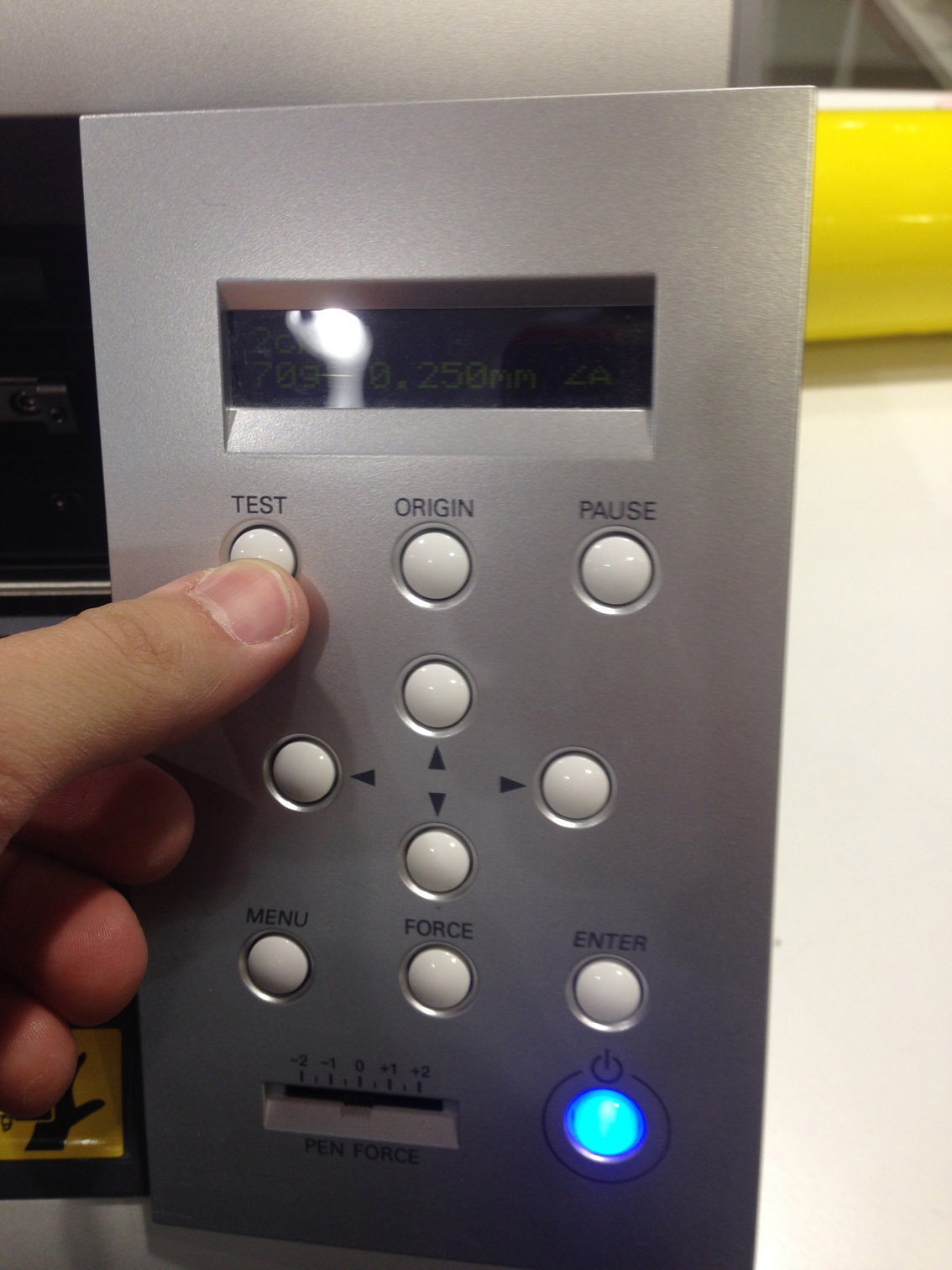
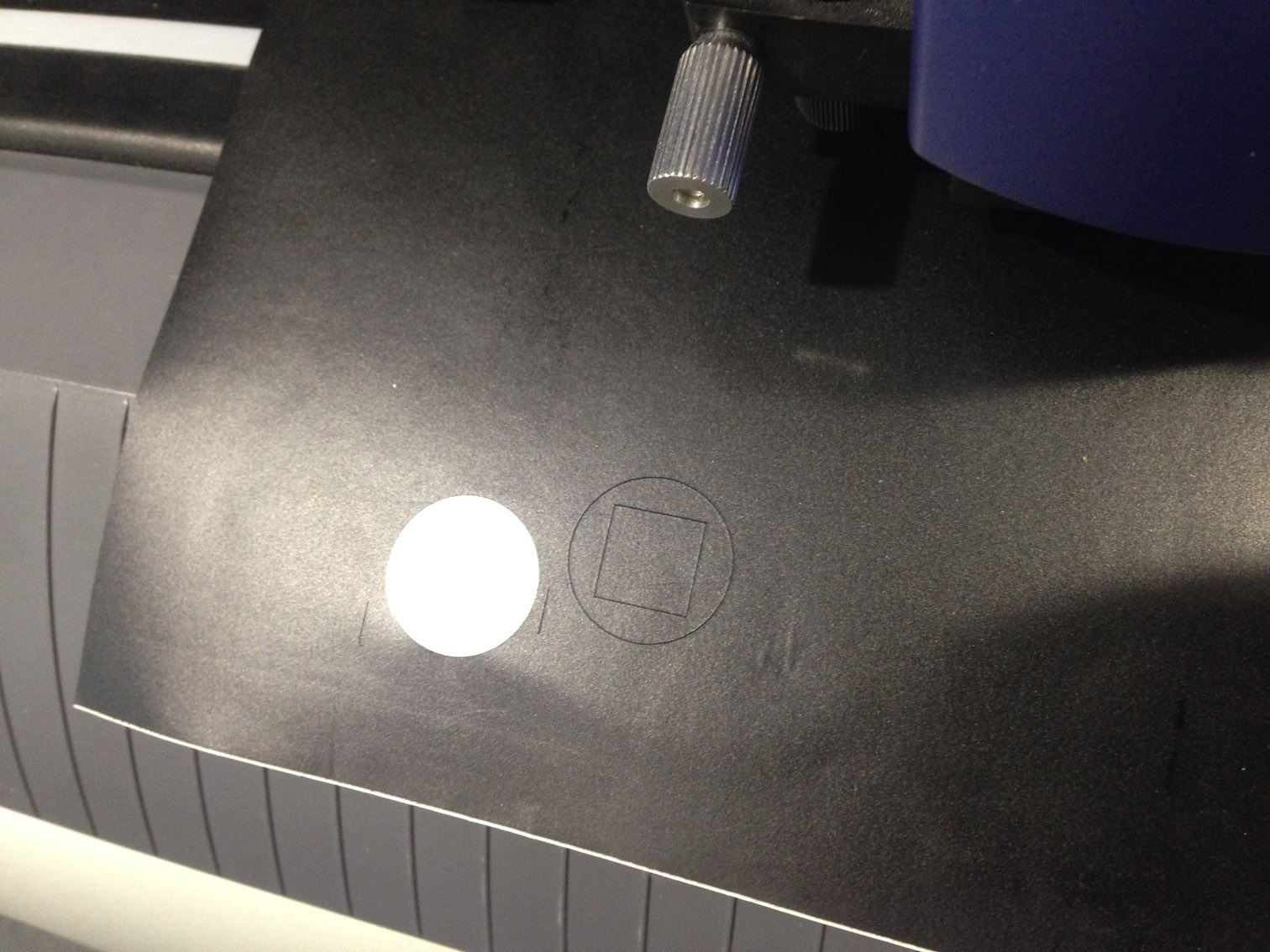
Now, I need to make some tests to make sure the machine uses the correct force to cut. On the control panel, select force and try different forces. First try with a 70g of force.
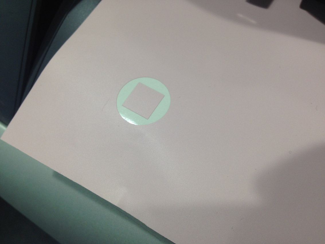
The machine cuts a square inside a circle. If the vinyl comes out easily, without having the white base being cut, then it is the correct force to use. Done! 70g is perfect.
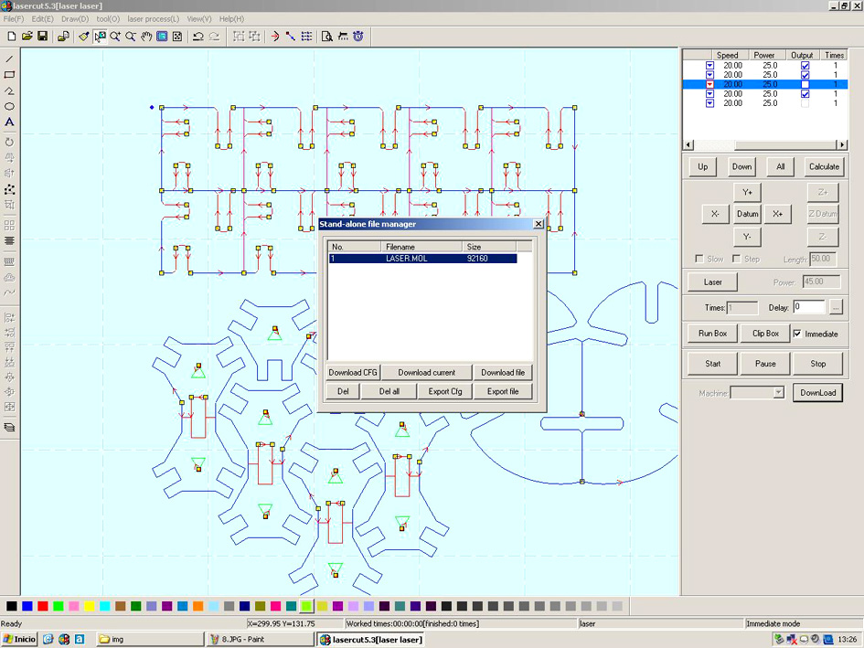
Going back to fab modules, change the force needed and calculate.
Once everything is ok, send.
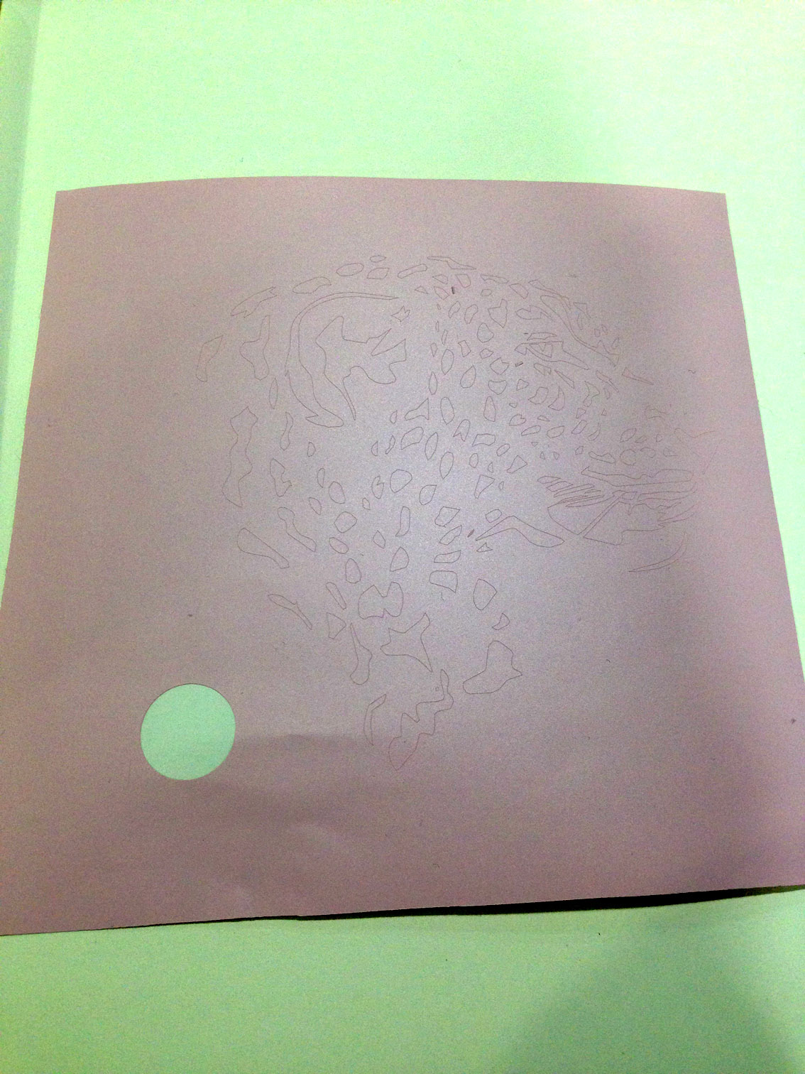
Result:
The Process Of Taking The Extra Vinyl Off
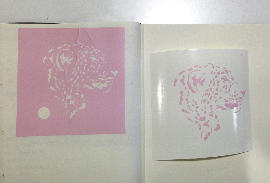
Then, I took a special paper named 'transfer paper' that is sticky on one side and put it on top of the piece that has not been separated. Put pressure to make sure all the little parts get stuck to the transfer paper and then, separate it from the white base.
Now, I have the final piece on the transfer paper and place inside my book. Carefully, separate the transfer paper from the vinyl little pieces, making sure they do not move.
On the .PNG file process, there is an image of this transfer paper I am talking about.
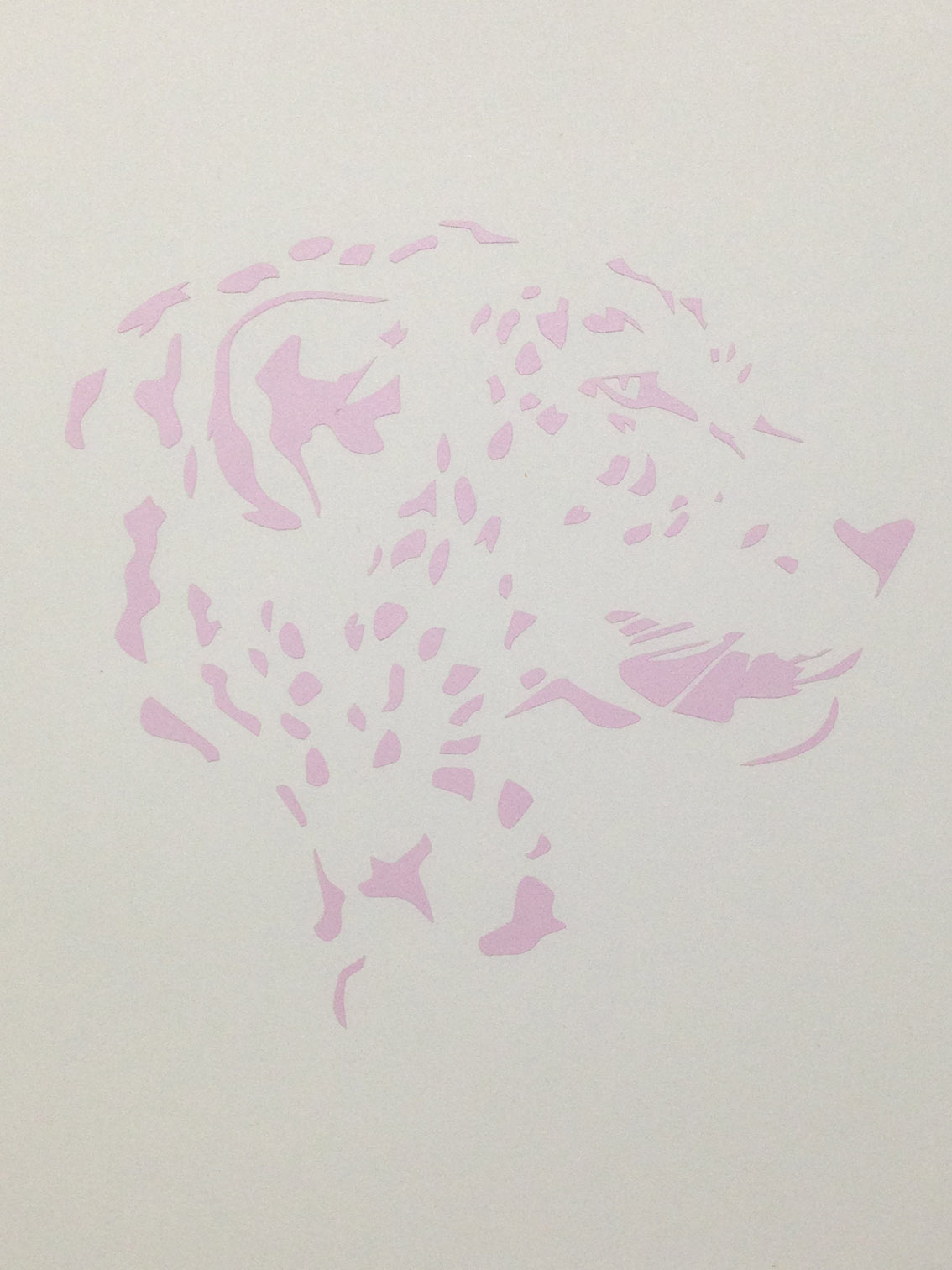
Final Result
Using a .PNG file
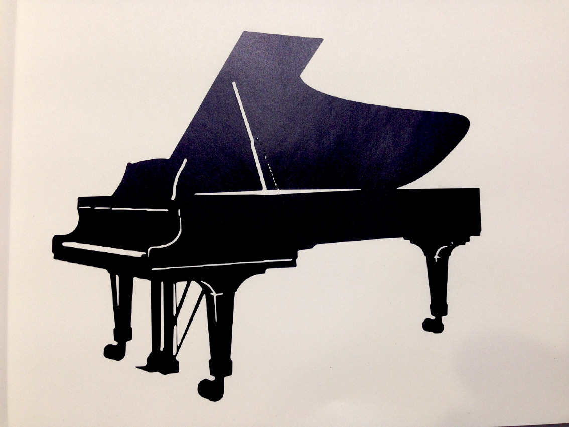
Again, to go through the whole process, I went to a friend's piano school website 'Escuela Piano Toccata' and took its logo: http://escueladepianotoccata.com/
Now, I have to modify the image. Import to Adobe Photoshop and make it have 1000dpi:
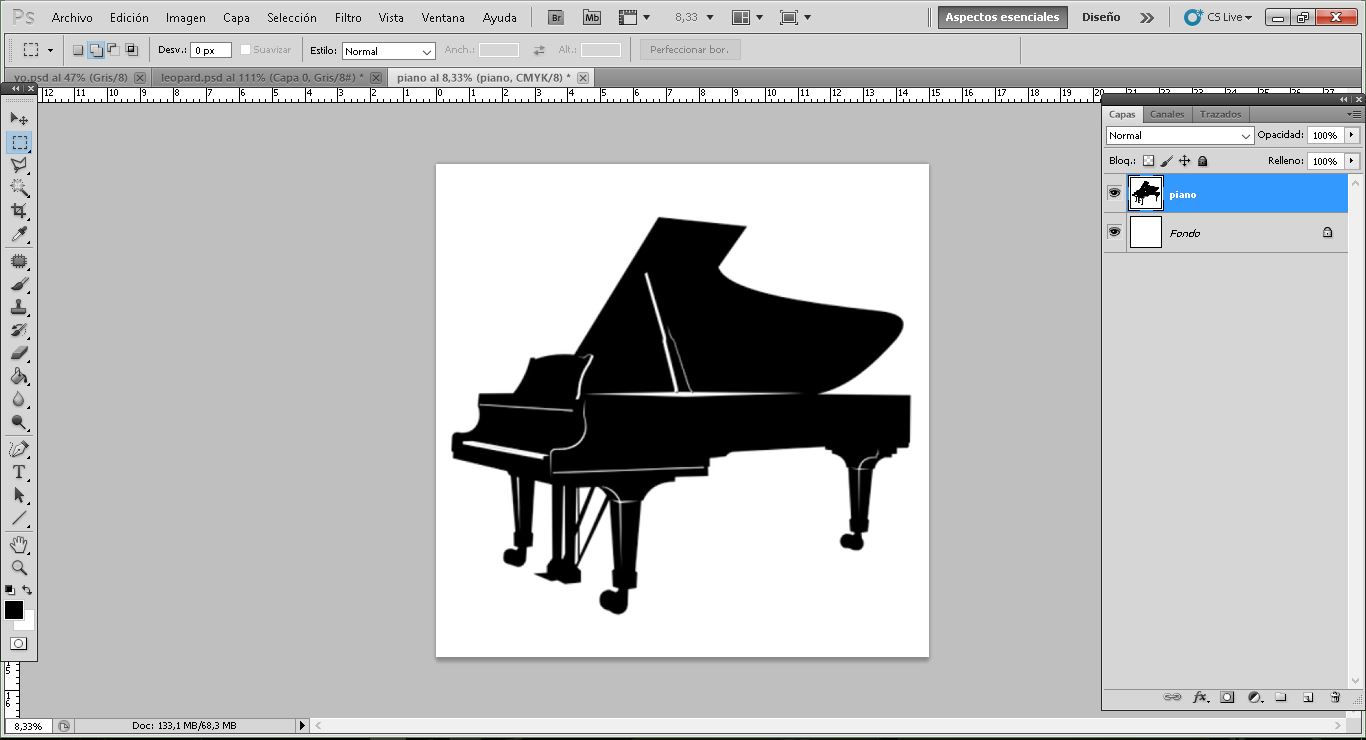
Now I have the image ready to import it to fabmodules.
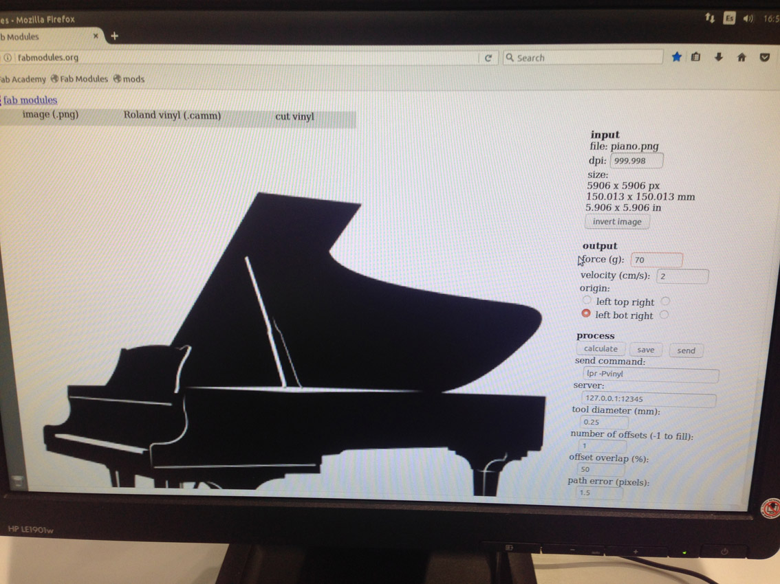
I turn on the computer and the machine as I did for the .SVG image entering what is needed. Then, open fabmodules:
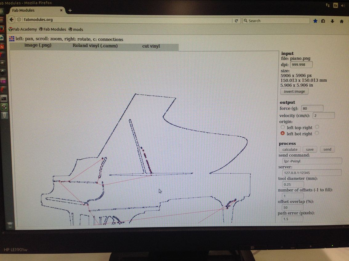
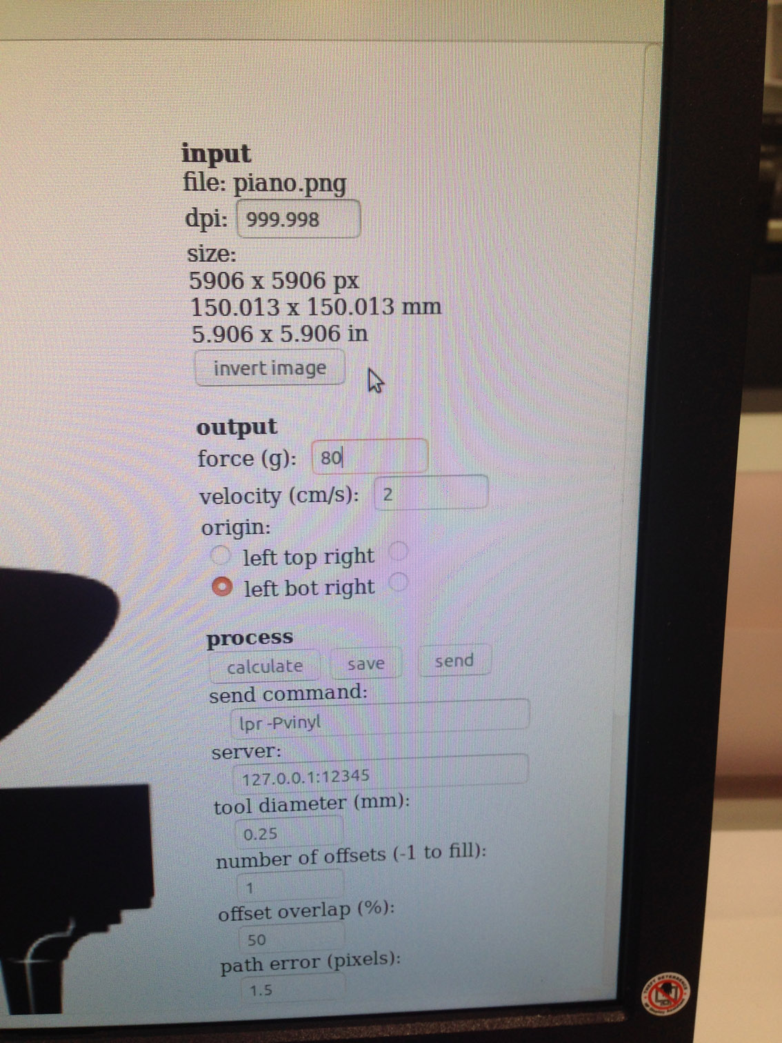
-input file: png
-output format: roland vinyl
-Process: cut vinyl
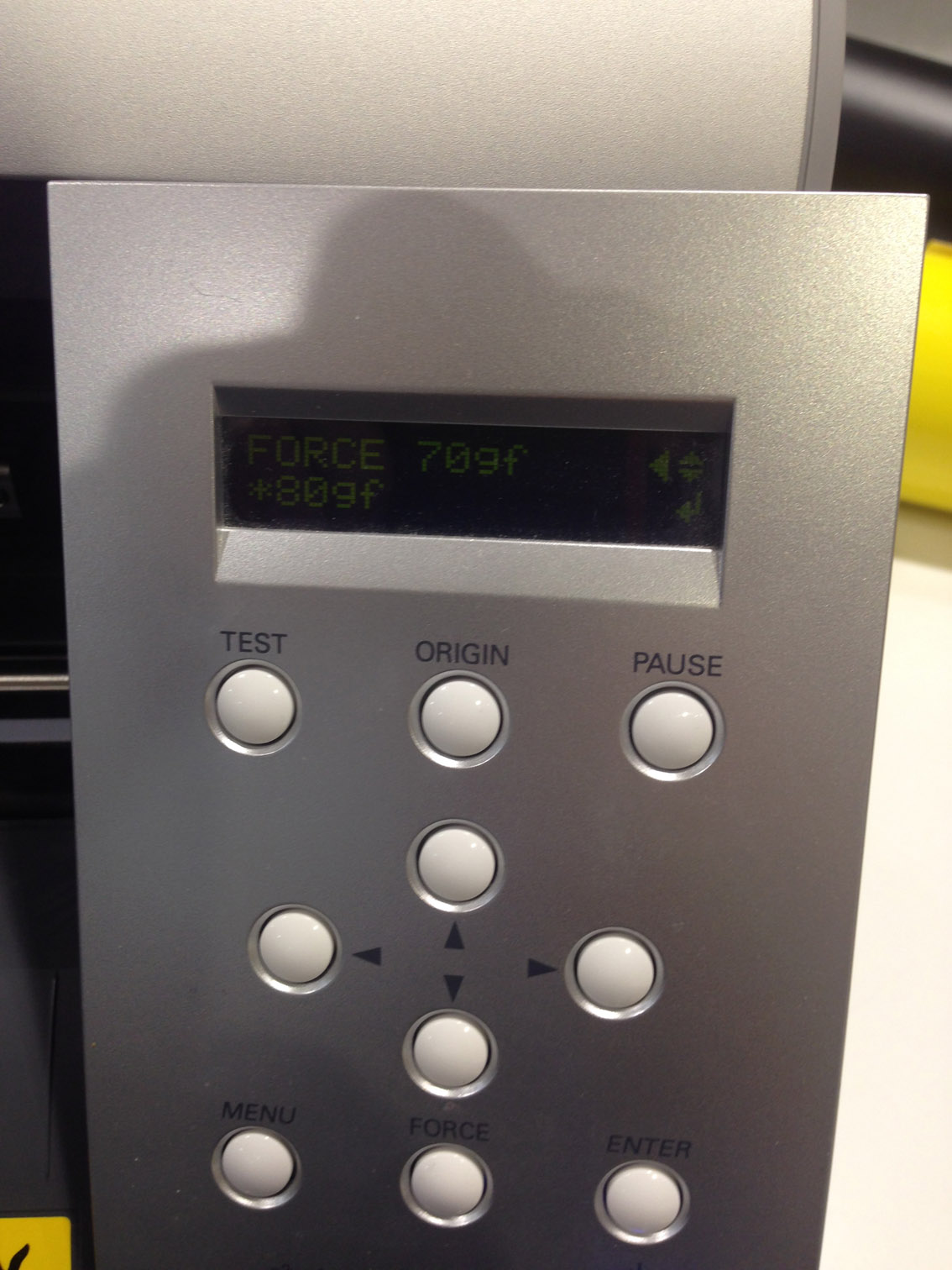
Again, as I cut the images in two different days, I needed to adjust the force by testing the machine:
force: 80 g
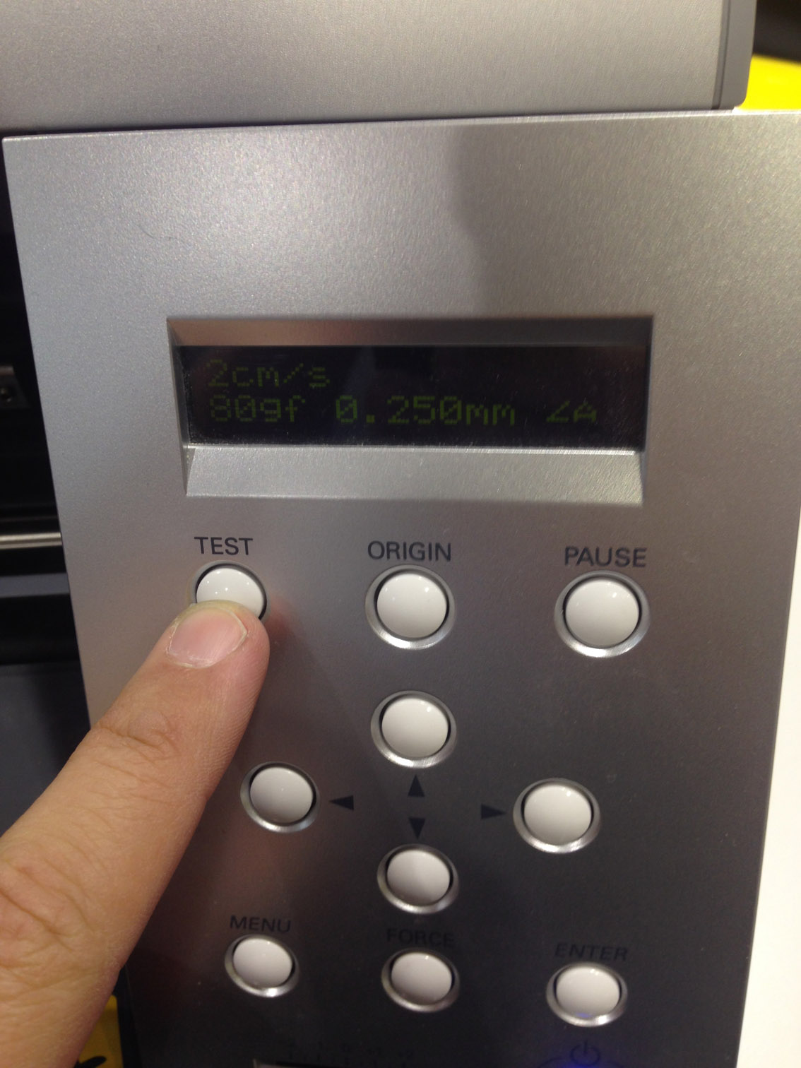
Test done and correct! Let's start!
After fabmodules has calculated the image. It's ready!
Done!
The final piece that came out from the machine had several problems as I had very thin lines. The material had not stuck together with the white base having the following problems:
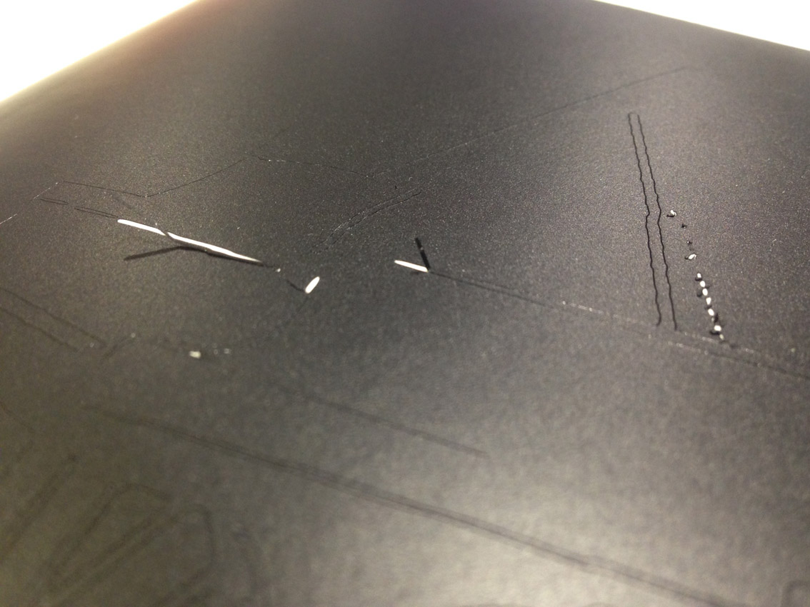
I carefully take all the different parts I do not need:
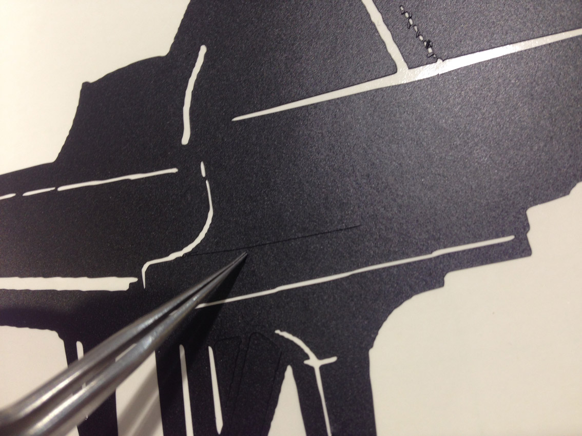
As done before, I take the transfer paper. I place it on top of my piano, and separated it from the white base. This is the transfer paper:
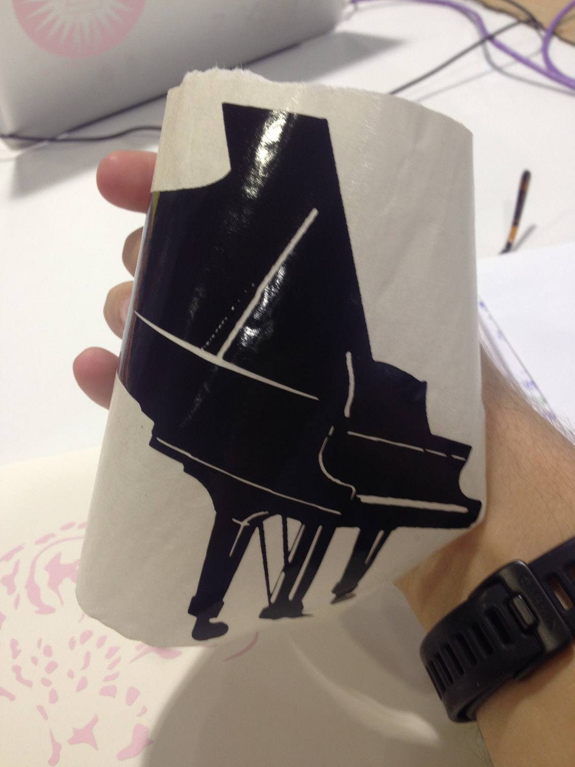
Final Result: