Fabacademy 2017
Tenth Week. Output Devices
Index
Tenth task
Output devices
This week task is to design, make and programme a board controlling an output device. I will use this week task to work on my final project and control a DC motor for the roller blinds of the fab window.
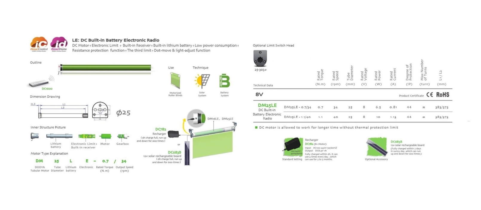
This is a good resource for calculating the neccesary torque of a roller blind DC motor. I am still not sure the final size of my window so I opted for a medium range torque of 1N.m. I also found a manufacturer which provides DC motor and the reduction gearbox in a handy format that can be installed inside the roller blind inner tube so it will keep things much tidier than installing the motor on one side.
This specific model also includes a battery which I will use to power the whole system. It brings its own controller circuit with a built in radio reciever which they will not be used, I will be using my own designed boards. It needs 8V and 0.81 Amps.
Designing the board
hello.H-bridge.44 board was used as a reference. It uses the A4953 Full-Bridge DMOS PWM Motor Driver which as its datasheet state "…is capable of peak output currents to ±2 A and operating voltages to 40 V". The chip has an exposed thermal pad for heat disipation.
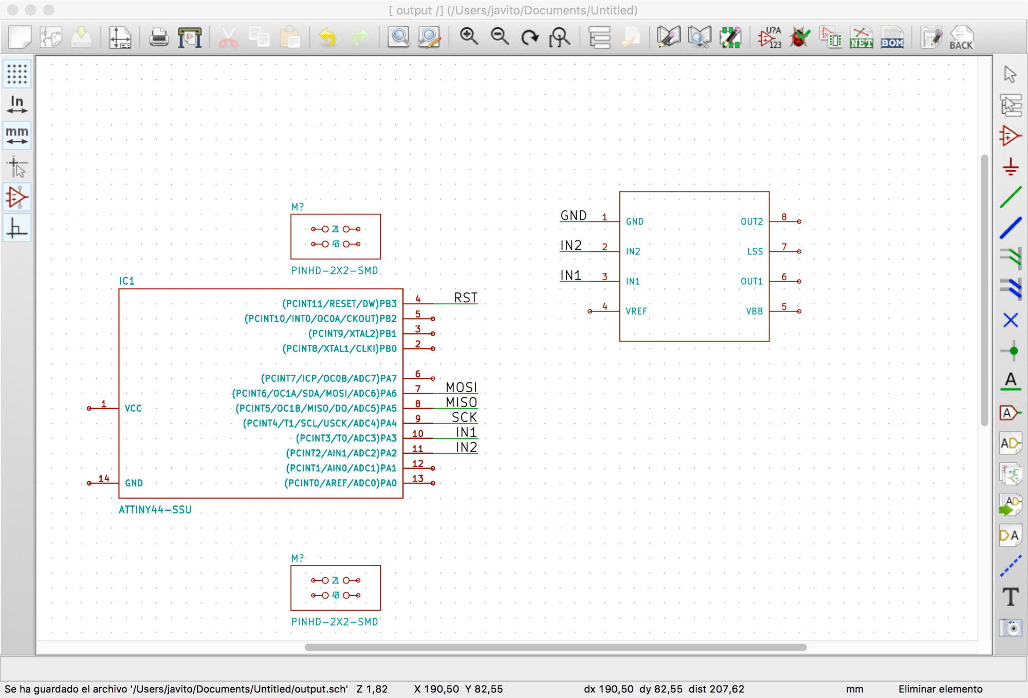
I decided to give a go to Kicad to have an Open Source alternative to Autodesk's Eagle. Interface was simple and felt more responsive than Eagle, I had huge problems with the libraries though which didnt feel as complete and sound as Eagle's ones. Had numerous issues when double checking the circuit and tried to customize the components myself but after a few hours of fiddling with them without much results I decided to go back to Eagle. Will try again at some point!
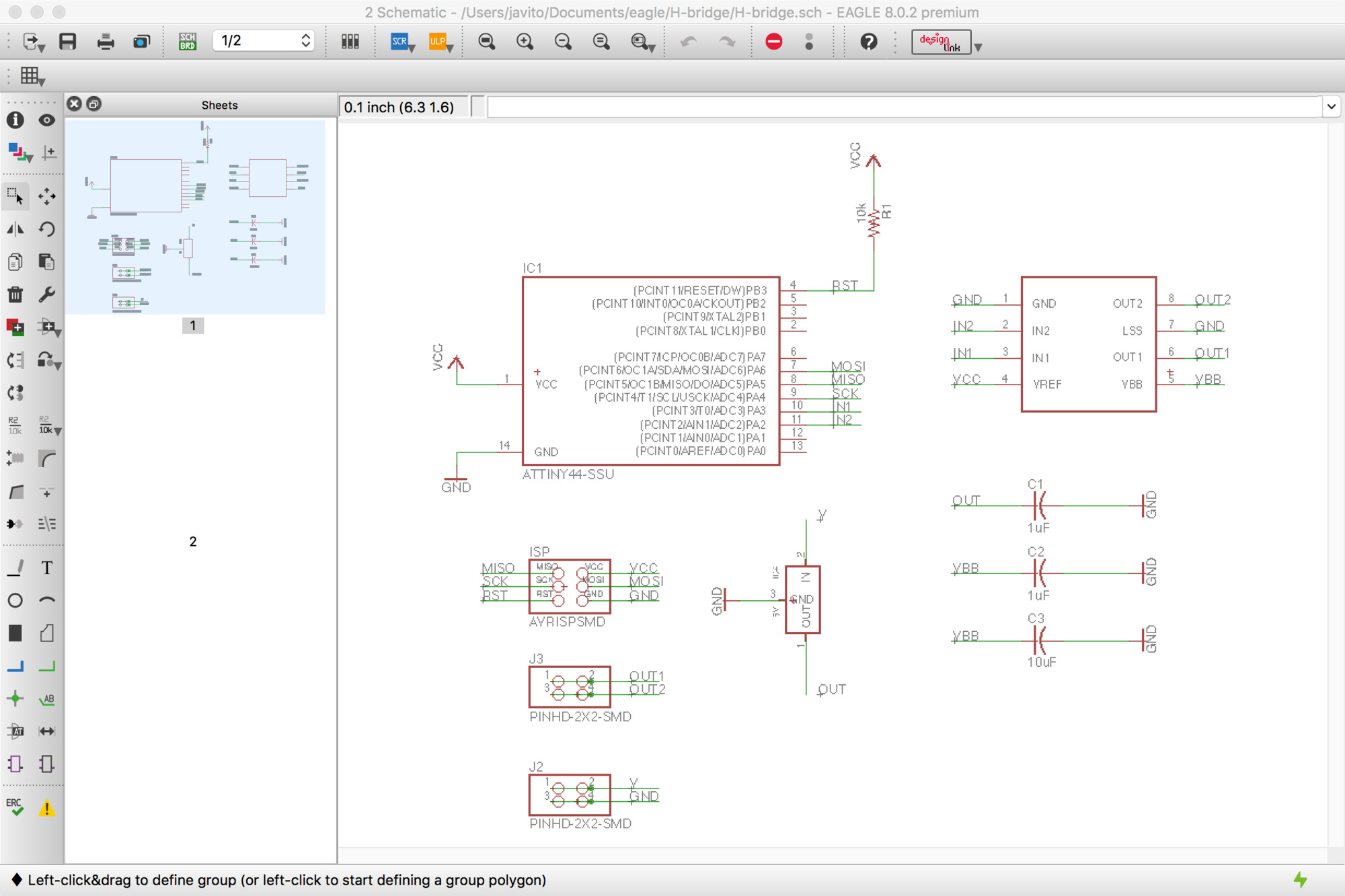
Back in Eagle, drawing the schematic was fast. I wonder if there is a grammar for electronic schematics as it is an abstract representation of a circuit, something must be in place to facilitate circuit reading. Anyway, the schematic completed in Eagle.
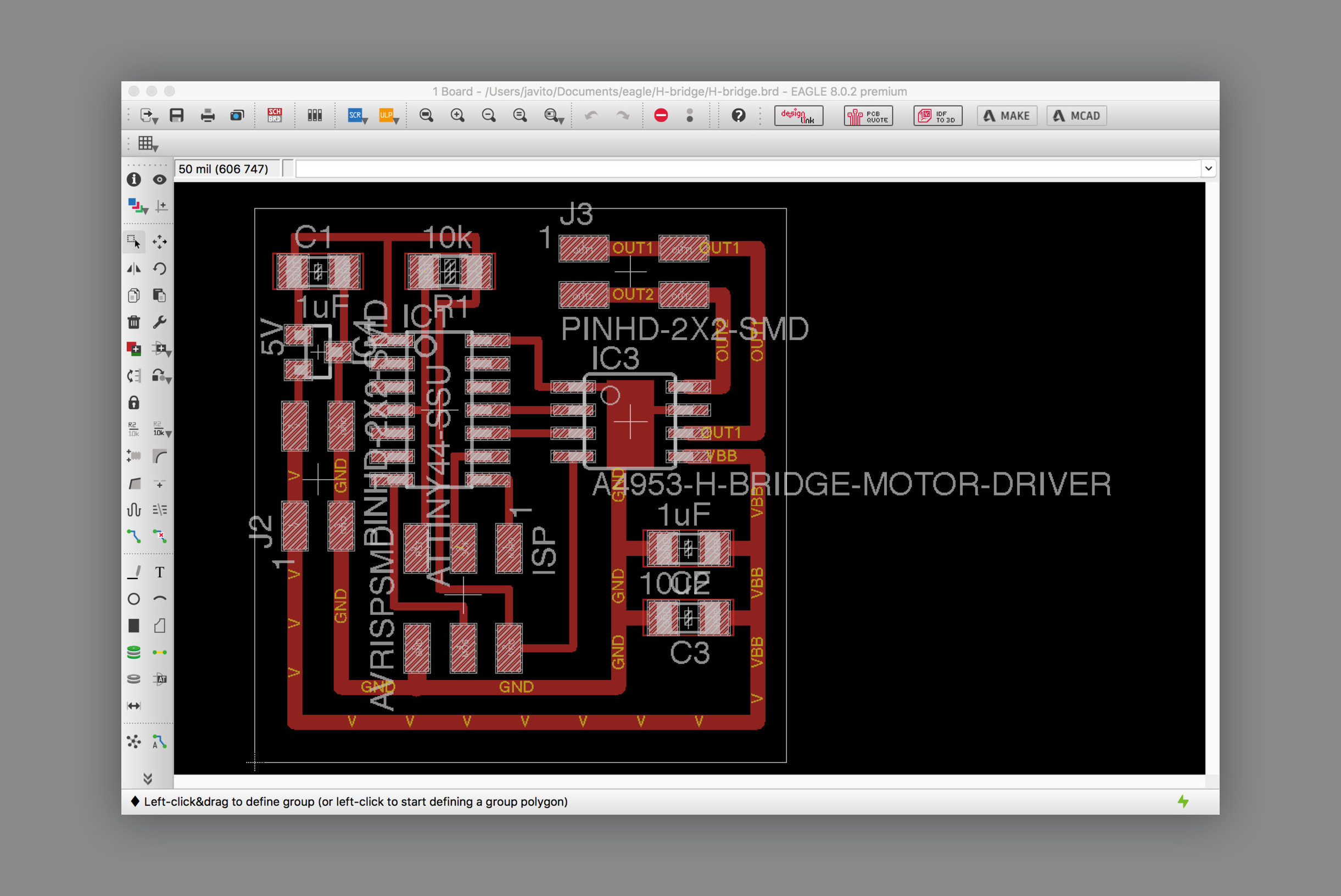
Placing the components and routing is always an interesting design challenge, with each new board the process fells more confortable and enjoyable. A couple of things to keep in mind for this board was to calculate the width for the motor supply routes and to draw a heat sink below the motor driver. For the first one, I used one of the many online calculators and entered the peak voltage and amps for my DC motor. It turned out that a 32mil width would be sufficient so I could keep the routes width multiple. I'm using 16mil for the small ones. For the second, I drawn a rectangle on top of the traces on layer 1, this caused some overlaping errors when checking the design rules which I simply approved manually.
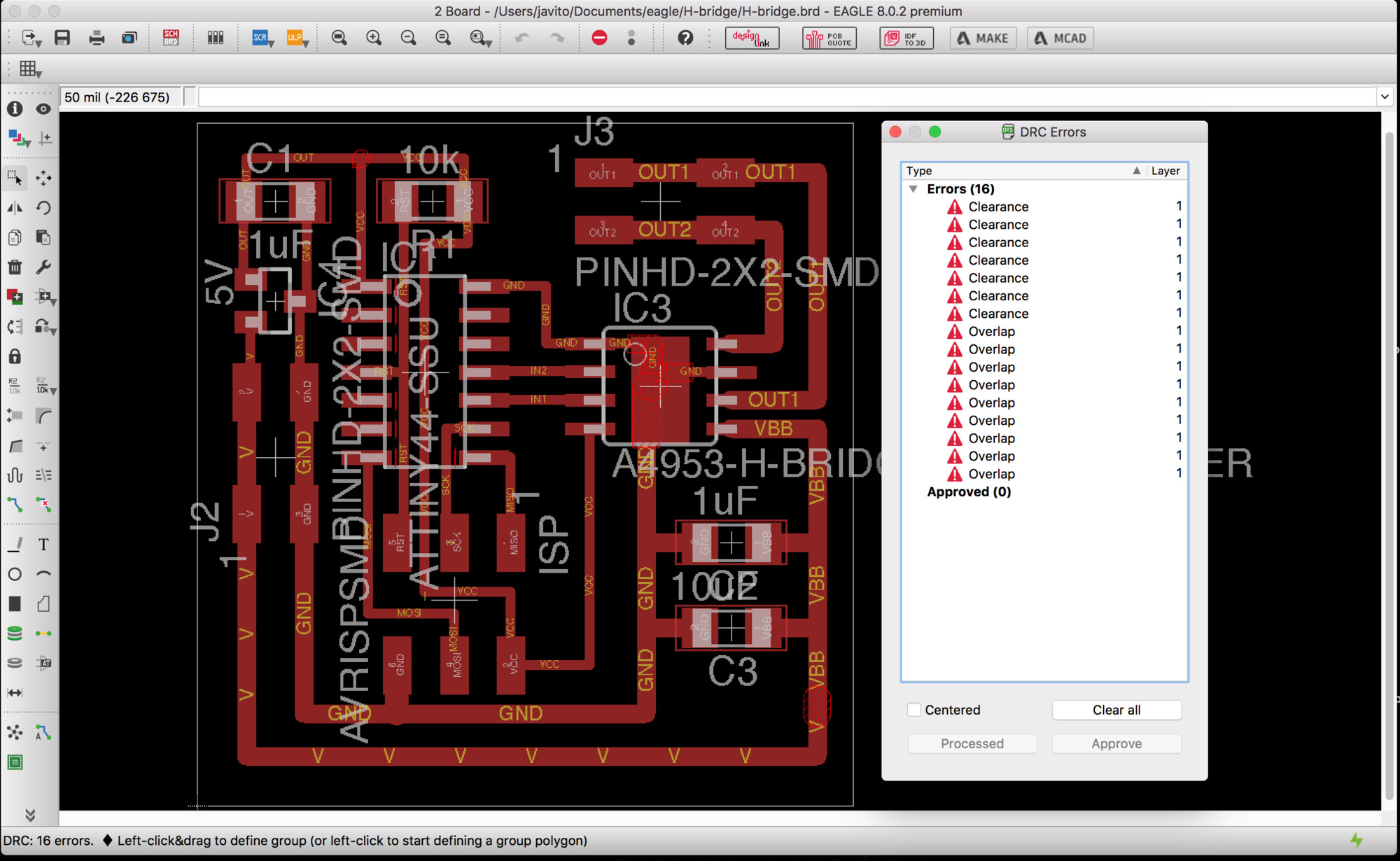
For the clearance error, I simply decrease the grid sbudivision to 5mil and placed the interior routes evenly. Below the final board design.
Fabricating the board
At this point, we are quite familiar with this process: Exporting png from Eagle –remember if you are using Mac with retina display you have to scale down the resulting image 50%–, using Mods to calculate the trace and cutting paths, milling the board and soldering the components. There were no remarkable issues.

Reusing roller blind DC motor
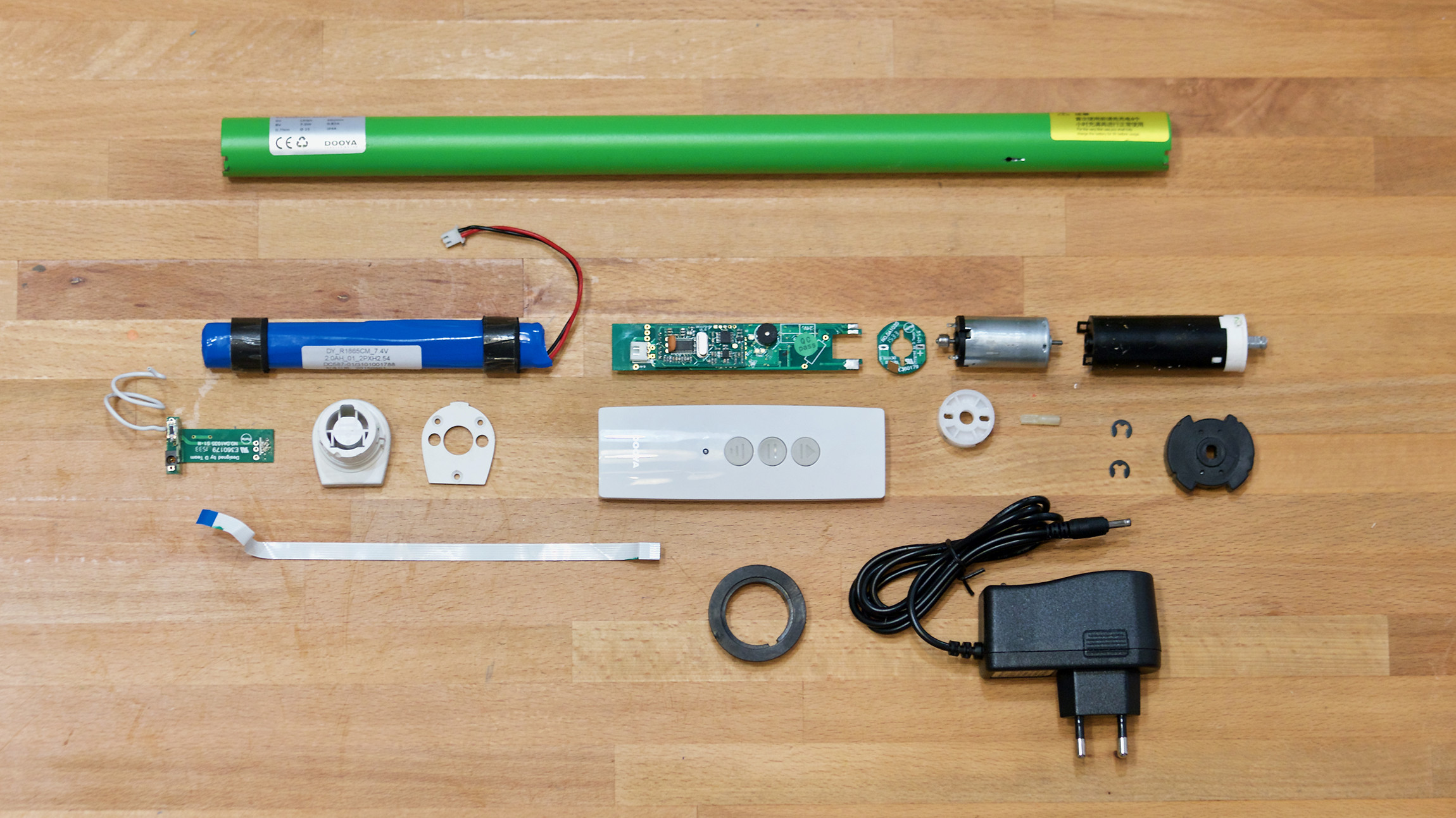
Once the part arrived I proceeded to its full disasembly. The process was more difficult than expected, no screws at the ends and all the internal elements were secured with two pins flushed with the tube. I cut a small groove at the center and used a flat screwdriver to remove them. The logic board had a clever design to attach it to the DC motor splitting the board into two perpendicular boards, slotting the main on into the other and securing it with solder.

Below you can see all the different parts of this clever design. I will be reusing the metal tube and most of the mechanical parts, the DC motor, the reduction box and the battery pack –together with its small charging circuit–. I will making my own controlling board which will have the same form factor than the shipped one.
Programming and testing
FOr programming I used hello.H-bridge.44.DC.c as a reference but for the moment I wont use PWM to control the speed of the motor. I will just program the board to move the motor forward and reverse. There are a number of things to learn this week:
- In my Embedded programming assigment I wrote the register directly with the byte in binary, this week I would like to use bitwise operators instead as it is used on the example above. I found a good tutorial in tutsplus Bitwise operations tutorial
- The physics of a DC motors defines the way motor drivers work, I have to study A4953 DC Motros driver datasheet in detail.
- If you are driving inductive loads, whereas it is a brushed or brushless DC motor, stepper motor, solenoid or a relay, you must have experienced a little bit of a problem in the form of an unwanted current flowing in the unwanted direction. This page explains Slow, mixed and fast decay modes in detail.
ATtiny44 GPIO ports
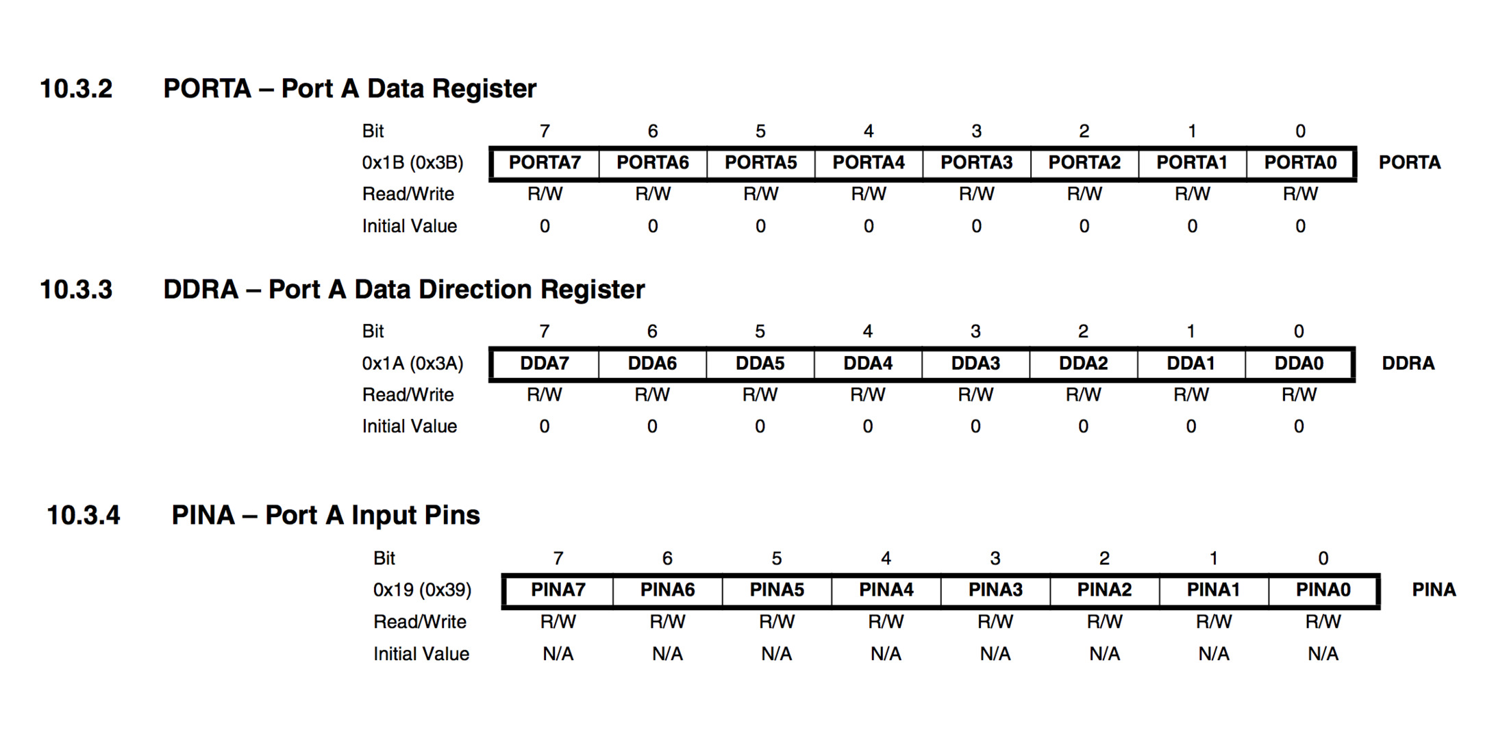
I found this tutorial particulary useful for understanding GPIO ports. Summarizing the tutorial: It is important to understand that to change setting for one single pin of the port, you have to change a particular bit in associated register. All its ports are 8 bit wide, every port has 3 registers associated with it each one with 8 bits and every bit in those registers configure pins of particular port. These three registers are:
- DDRA register. Configures data direction of port pins. Writing 0 to a bit in DDRA makes corresponding port pin as input, while writing 1 to a bit in DDRA makes corresponding port pin as output.
- PINA register. Used to read data from port pins. In order to read the data from port pin, first you have to change port’s data direction to input. If port is made output, then reading PINx register will give you data that has been output on port pins
- PORTA register. Used for two purposes:
- To output data when port is configured as output. Corresponding pins becomes output pins. Now you can write data into respective bits in PORTA register. This will immediately change state of output pins according to data you have written
- activate/deactivate pull up resistors – when port is configures as input. When you set bits in DDRA to 0, then corresponding bits in PORTA register are used to activate/deactivate pull-up registers associated with that pin. In order to activate pull-up resister, set bit in PORTA to 1, and to deactivate set it to 0.
- In input mode, when pull-up is enabled (PORTA is 1) default state of pin becomes ‘1’. So even if you don’t connect anything to pin and if you try to read it, it will read as 1. Now, when you externally drive that pin to zero, only then it will be read as 0.
- if you configure pin as tri-state (PORTA is 0). Then pin goes into state of high impedance. In this case, if pin is left floating (i.e. kept unconnected) then even small static charge present on surrounding objects can change logic state of pin. If you try to read corresponding bit in pin register, its state cannot be predicted.
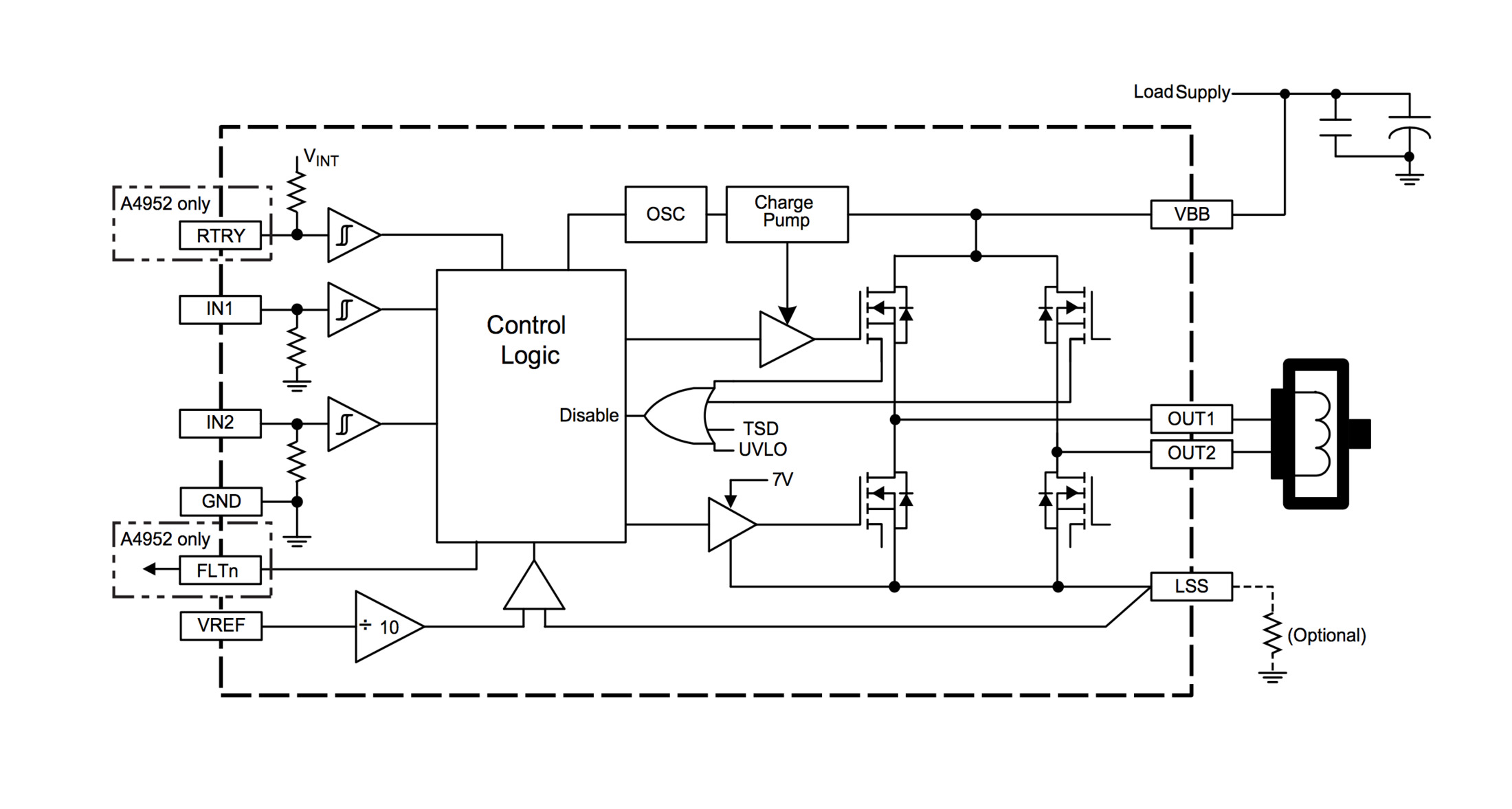
Regarding the motor driver,The A4953 overcurrent protection can only be reset by putting the device into standby mode or by cycling the power to VBB. In order to use PWM current control –page 7 of the A4953 Datasheet– a low-value resistor is placed between the LSS pin and ground for current sensing purposes.
The control truth table and timing diagram, describes how the signal needs to be formed. In my code I am just driving the motor forward (IN1=0, IN2=1) for a determined ammount of time. Then braking the motor (IN=1, IN2=2). And finally, driving the motor in reverse (IN1=1, IN2=0). Note that as explained in this tutorial,Slow, mixed and fast decay modes in detail, you cant change from foward to reverse directly as driver will protect itselff from the inductive load generated by the motor, for this reason you need to brake first –a mere 15 microseconds will suffice– before driving the motor to the opposite direction.
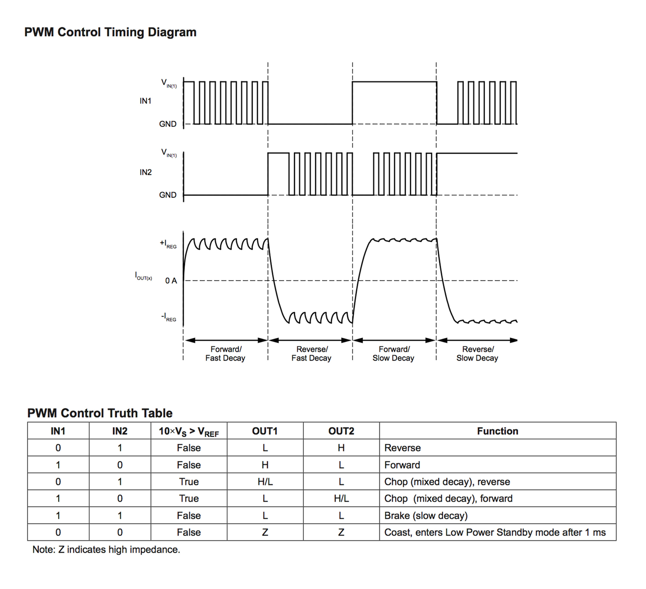
This is my final code and below the video showing the resulting behaviour:
//
// DC.H-bridge.c
//
// http://www.nongnu.org/avr-libc/user-manual/group__avr__io.html
#include <avr/io.h>
// http://www.nongnu.org/avr-libc/user-manual/group__util__delay.html
#include <util/delay.h>

// The | operator compares each binary digit across two integers and gives back a 1 if either of them are 1
#define output(directions,pin) (directions |= pin) // set port direction for output. directions = directions | pin
#define set(port,pin) (port |= pin) // set port pin
// The & operator compares each binary digit of two integers and returns a new integer, with a 1 wherever both numbers had a 1 and a 0 anywhere else
#define clear(port,pin) (port &= (~pin)) // clear port pin

// 10.1.1 Configuring the Pin
#define bridge_port PORTA // H-bridge port
#define bridge_direction DDRA // H-bridge direction
#define IN1 (1 << PA3) // IN1
#define IN2 (1 << PA2) // IN2

int main(void) {
   // CLKPR Clock Prescale Register 6.5.2 attiny44 and table 6-11
   // To avoid unintentional changes of clock frequency, a special write procedure must be followed to change the CLKPS bits:
   // 1. Write the Clock Prescaler Change Enable (CLKPCE) bit to one and all other bits in CLKPR to zero.
   // 2. Within four cycles, write the desired value to CLKPS while writing a zero to CLKPCE.
   // set clock divider to /1
   // CLKPR = 0b0000000 CLKPR = 0b1000000 (1 << CLKPCE) The << operator shift number 1 seven places to the left
   CLKPR = (1 << CLKPCE);
   // The | operator compares each binary digit across two integers and gives back a 1 if either of them are 1
   CLKPR = (0 << CLKPS3) | (0 << CLKPS2) | (0 << CLKPS1) | (0 << CLKPS0);
   //
   // initialize H-bridge pins
   //
   clear(bridge_port, IN1);
   output(bridge_direction, IN1);
   clear(bridge_port, IN2);
   output(bridge_direction, IN2);
   //
   // main loop
   //
    while (1) {
     clear(bridge_port, IN1);
     set(bridge_port, IN2);
     _delay_ms(3000);
     set(bridge_port, IN1);
     set(bridge_port, IN2);
     _delay_ms(15);
     set(bridge_port, IN1);
     clear(bridge_port, IN2);
     _delay_ms(3000);
    }
 }