Assignments:
- Automate your machine
- Document the group project
- Document your individual contribution.
--- WORKFLOW ---
We have been designing the machine for some time and have followed this workflow.0. Creative Thinking Machine and References
1. First sketches and drawings of the machine
2. Separation of components and allocation of materials and explosions.
3. In-depth definition of the machine and Assignment of individual work.
--------------------------------------------------------------
4. Design of the drawing and cutting parts
5. Prototyping assembly and corrections
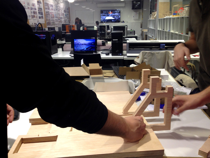
6. Assembly of components and corrections between parts
7. Checking and improvement.
Here you can see the complete documentation of the group assignment:
--- My individual contribution. ---
I have been chosen by my colleagues as a designer, and my work consisted of designing a many of the parts used in our machine.
1. Redesign of the Stage to adapt it to our material:
2. Design of the base and paper holders.
3. Cutting and mounting the base.
4. Design and assembly of parts in 3D printing.
5. 3D integration of the machine, artwork and drawings.<
6. Engine housing.
7. Assembly, sanding, screwing, gluing ....
8. Engraving the base with laser cutting machine.
9. Making the Poster of our machine
10. Make a good Logo<
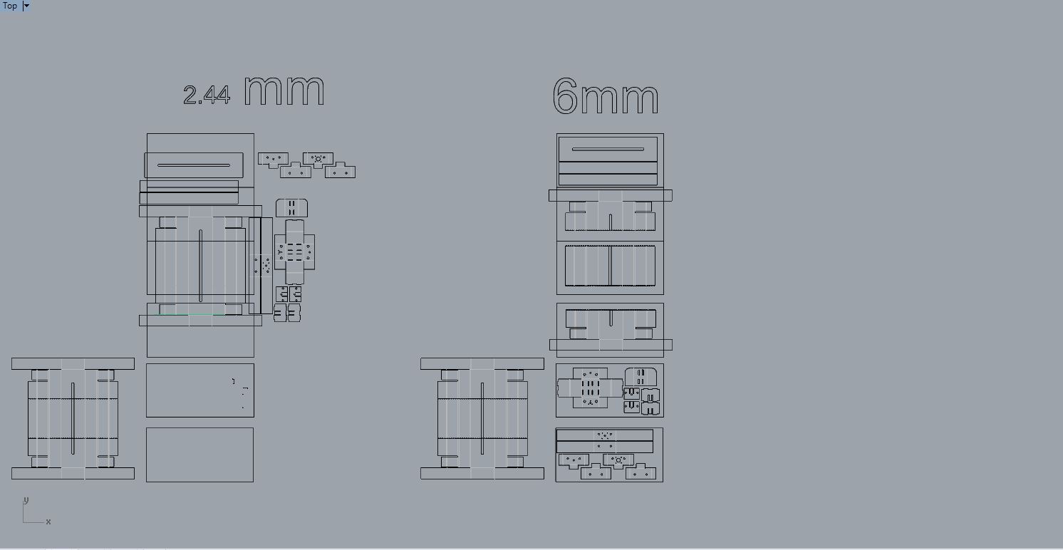
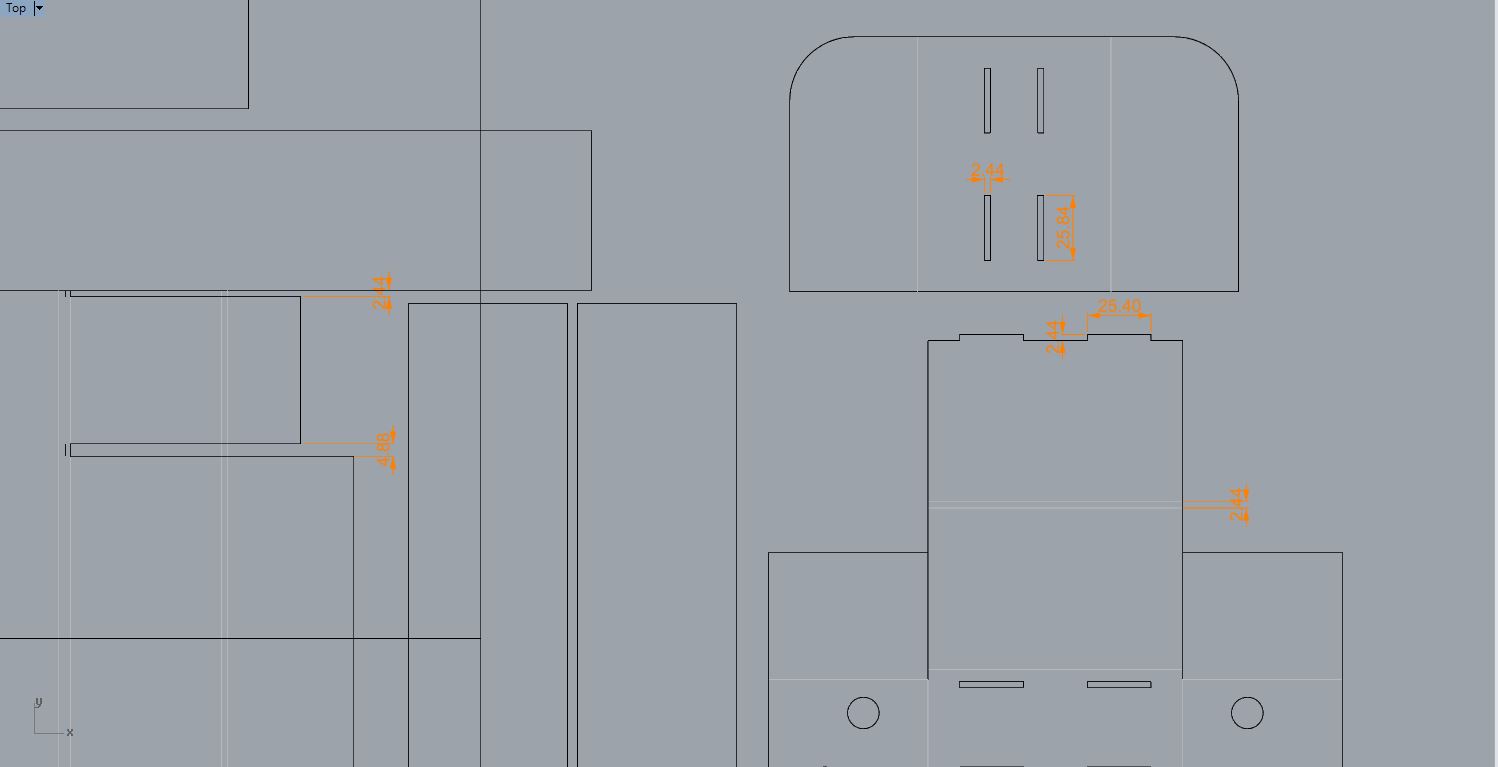
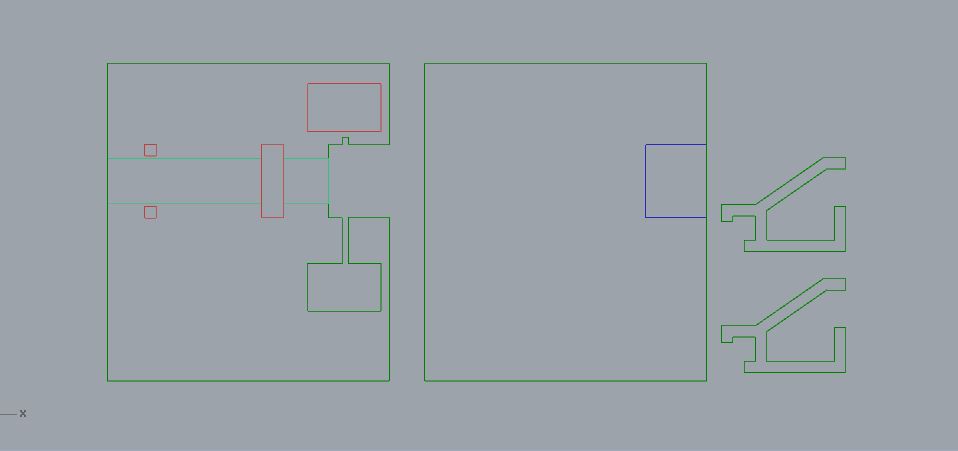
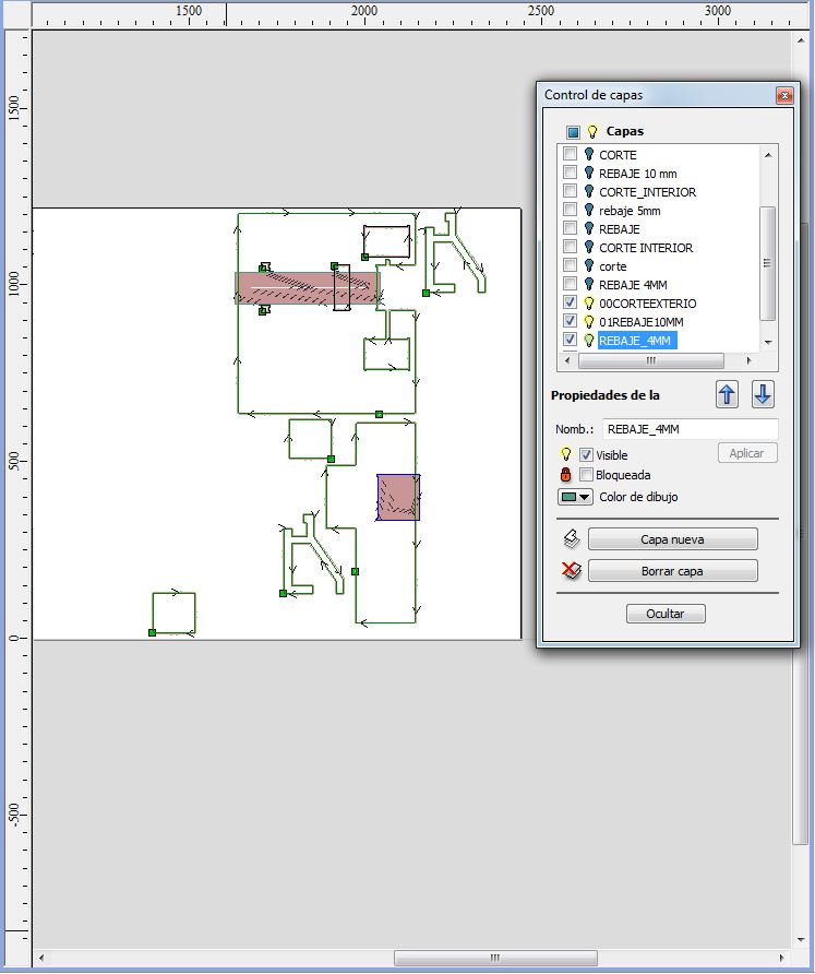
1. Redesigning Stages :
he first thing I did was to have to redesign the stage, because in the files came with another thickness of material and when doing the bake in grasshopper also did not fit well the plans to the design, appeared duplicated lines and open polylines.
Description of my work:I have changed the joints, in the original measured 4.04m, I have changed it to 3mm and when take measures of the material I had to change at 2.44mm and taking into account the total kerf
These is because We had problems from grasshopper, to adapt it to our material and the plans did not bake complete.
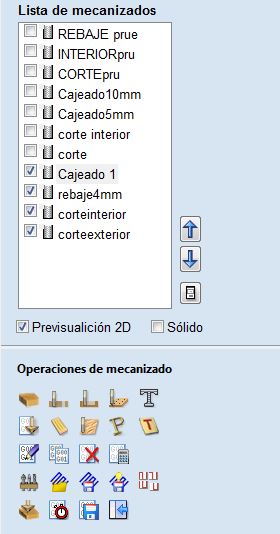
Software: Rhinoceros 5.0
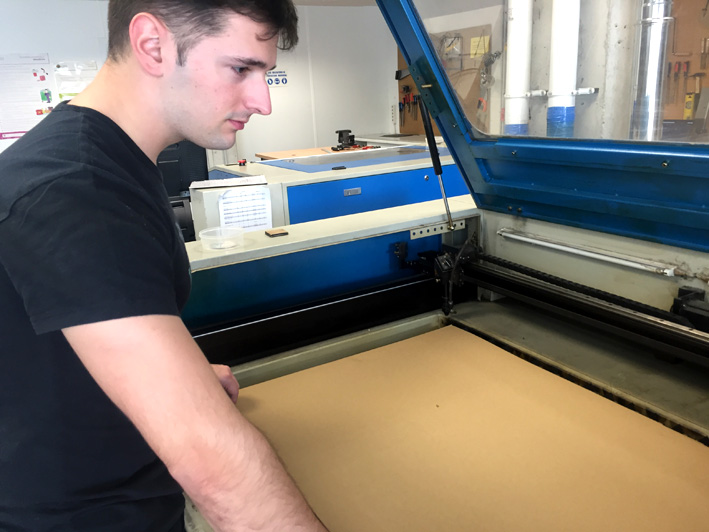
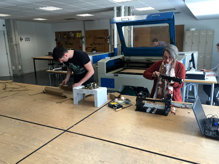
Then we cut the 3mmcardboard stage in laser cutting machine between all partners.
Material: 3mm Cardboard.
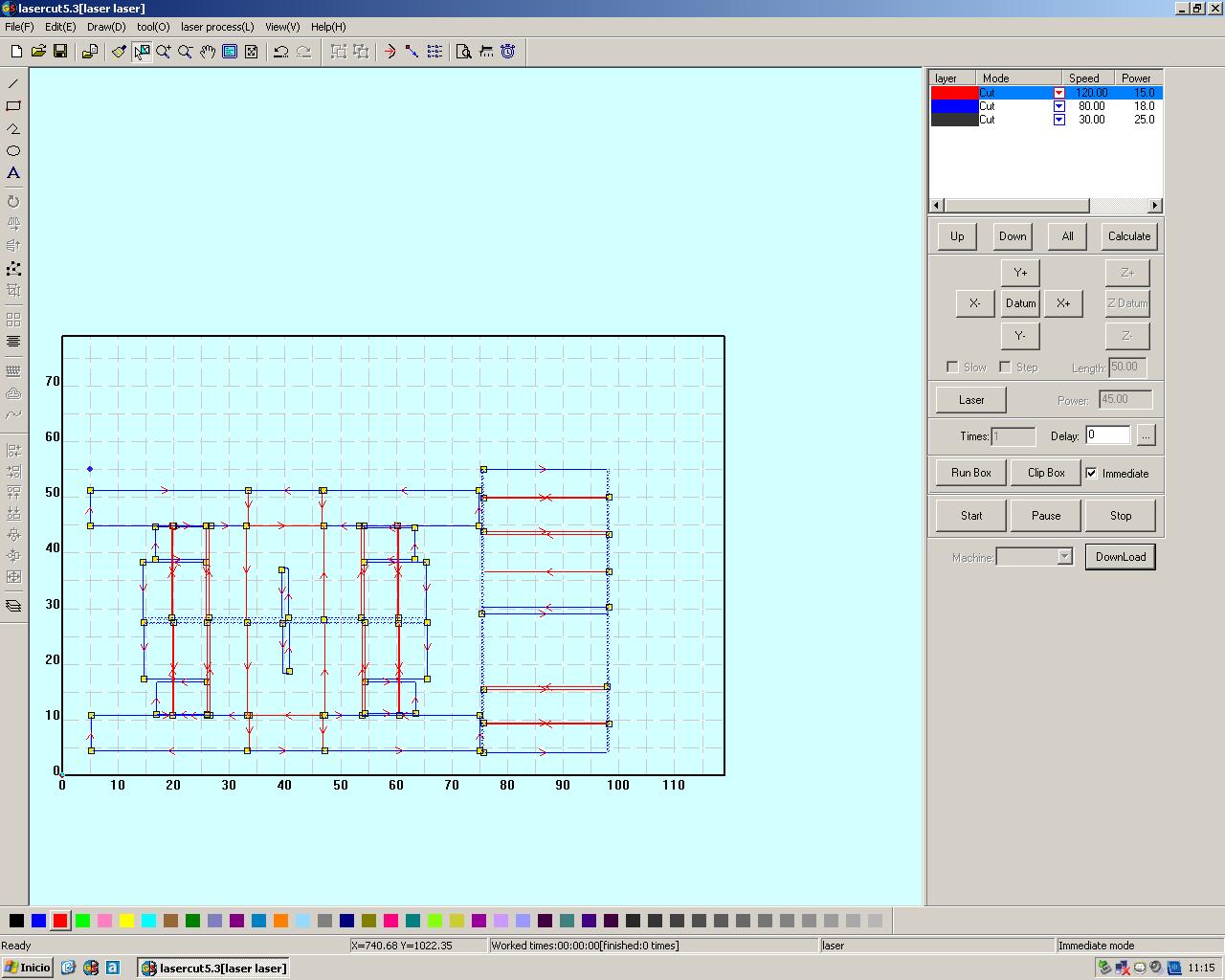
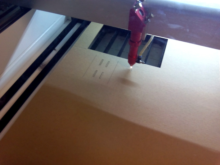
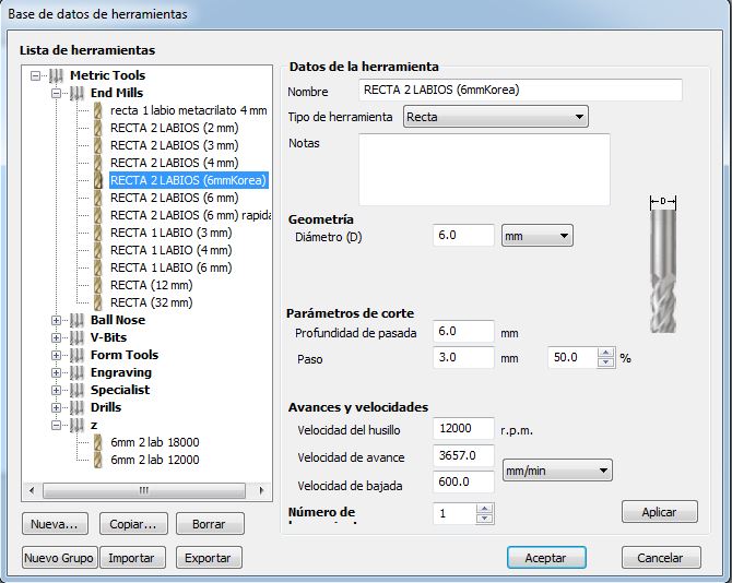
The settings of the cut it was:
CUT -
Speed: 80
Power:18
CPower:13
Surface cut -
Speed: 100
Power:15
CPower:12
FILES:
Re-design file of stage
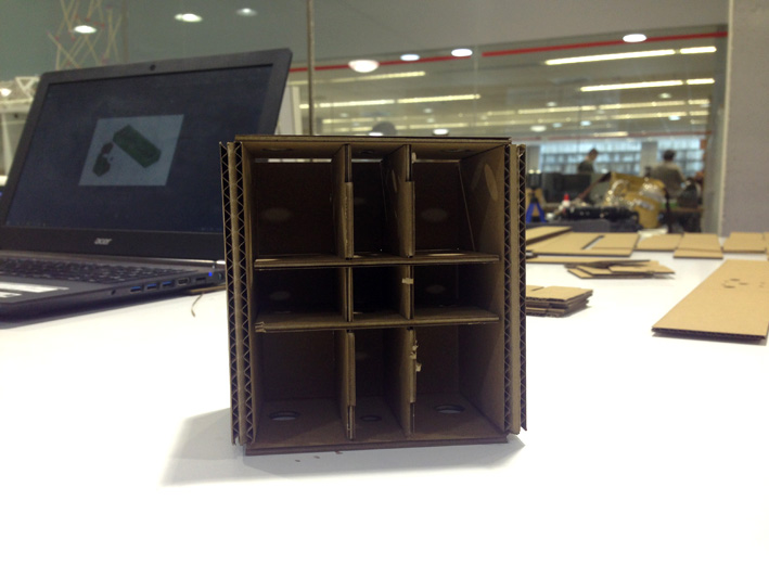
2. Design of the base and paper holders
Description : A rigid and flat wooden base to support the weight of the machine elements, and a paper holder Attached to the base
The process has been as follows:
That it had the width of the stage, the length sufficient for the machine parts, that all the pieces were at the desired height with trims, and that between them they would not get in the way
Dimensions: 562mm x 500 mm
trims/ cut-down :
1. Joint with support of the paper roll
2. Path of paper
3. Paper hole punch
4. 3 trims correspond to the roller system
The difficulty of the base is to make all the components of the machine fit well with the base, so it was necessary to work in 3D with all of them.
However, for safety, in some specific points we leave the possibility of adjusting the height.
The workflow was:
1. Make a sketch in 2D in rhinoceros
2. Extrude the sketch and do it in 3D and place the other designed elements
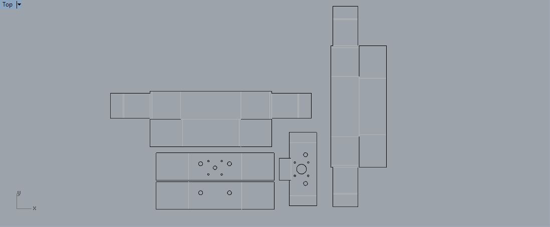
3. Go back to 2D to export cutting planes
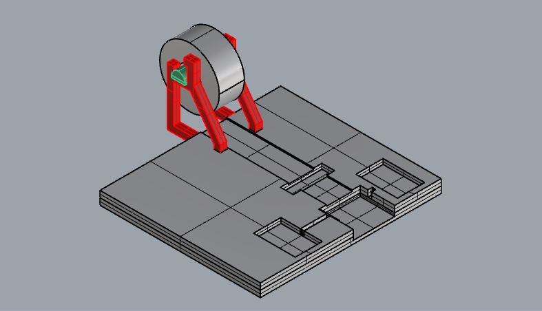
Making 3D model with other parts of the project.
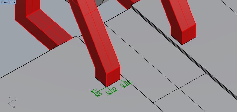
Adjusting material tolerance measurements .
Going back to 2D.
FILES:
3D base and cut plan.3. Cutting and mounting the base.
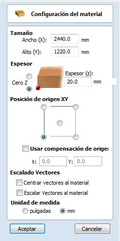
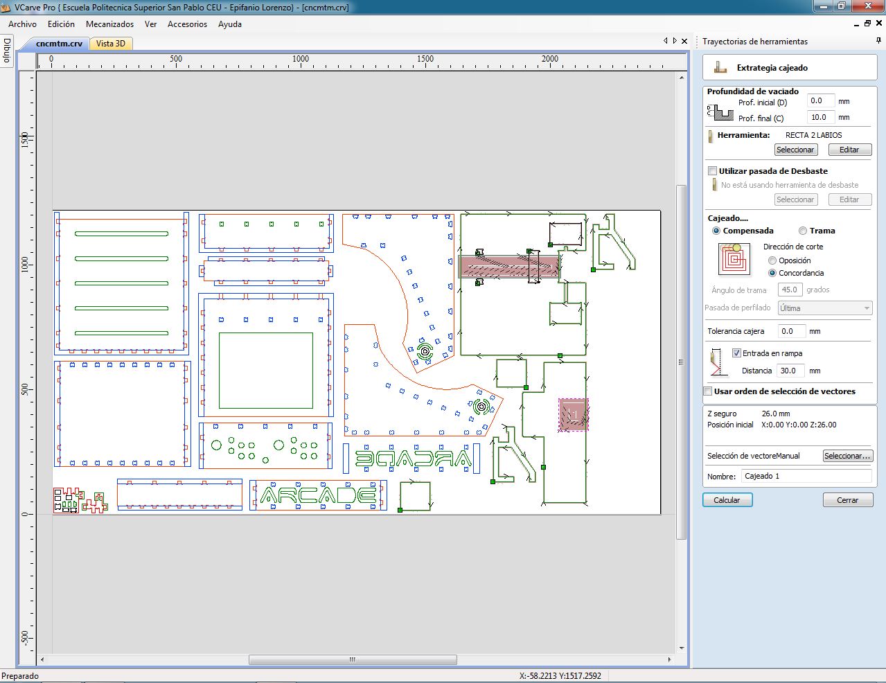
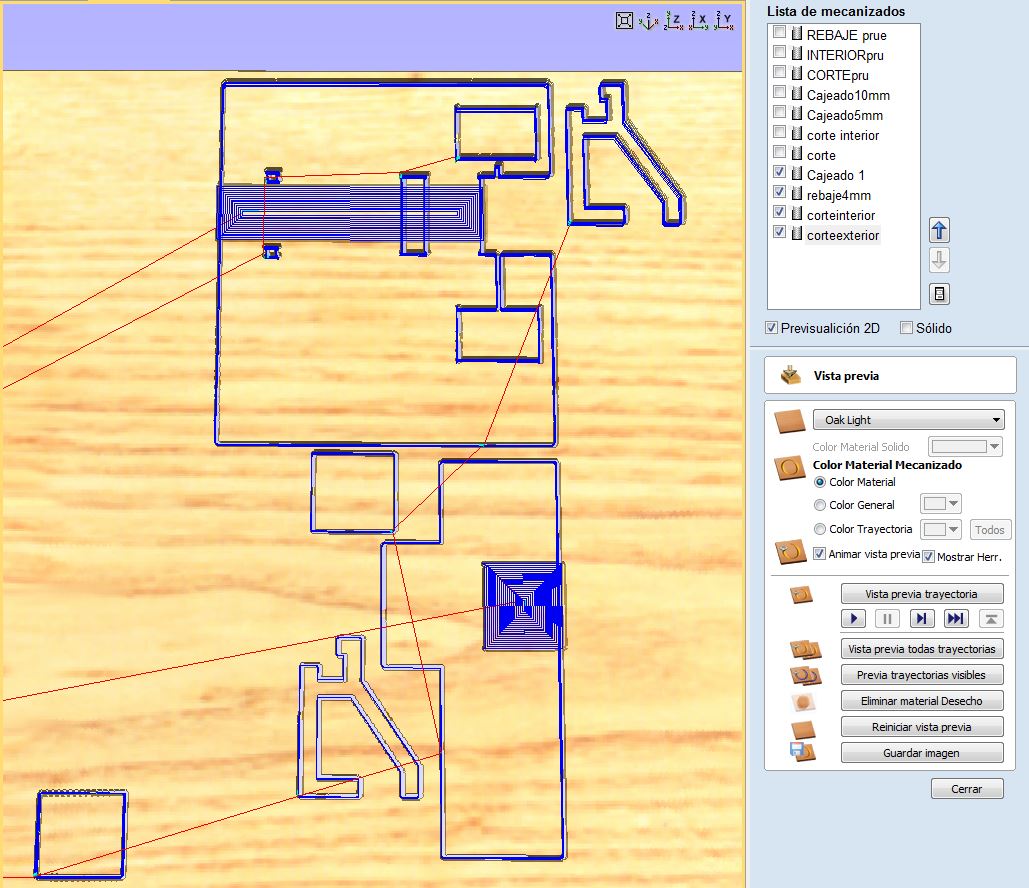
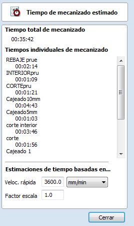
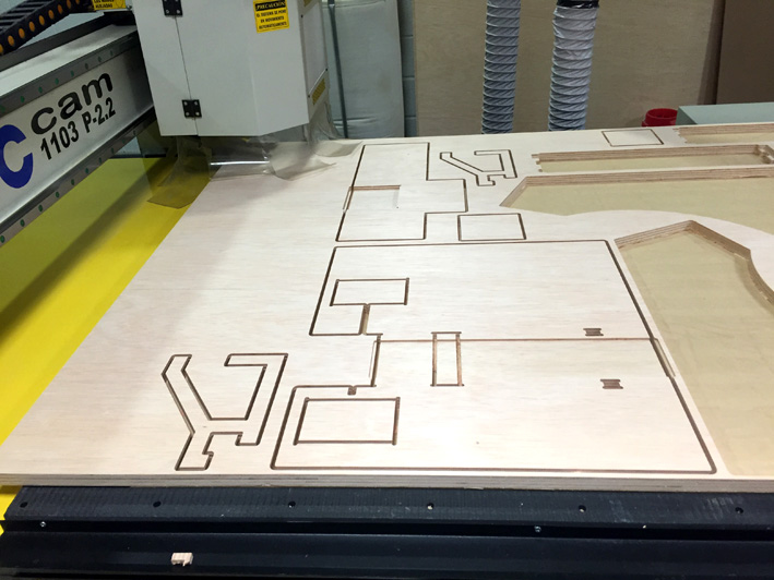
Then I cut the 20mm Plywood in the CNC cutting machine
Material: 20mm Plywood.
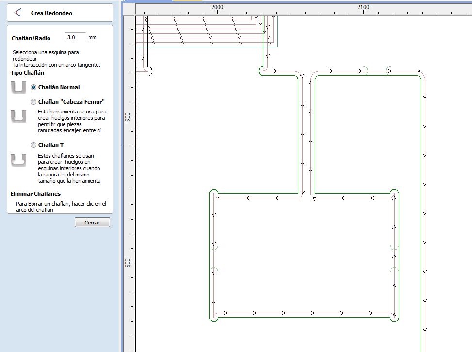
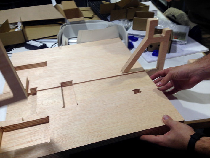
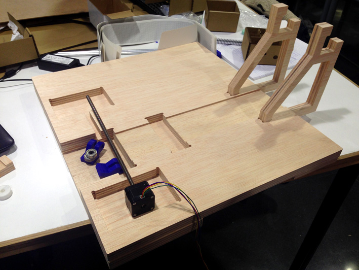
From here we have seen the joints that interest us most.
In this case the hidden joint that I like for my arcade machine is this, which measures exactly 15.50mm by 10.50 and with a 10mm tolerance of 0.5mm.
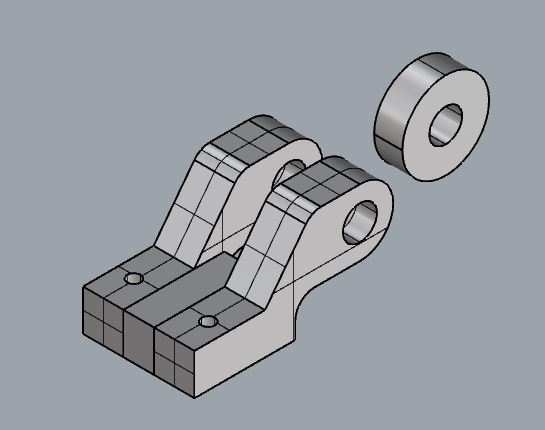
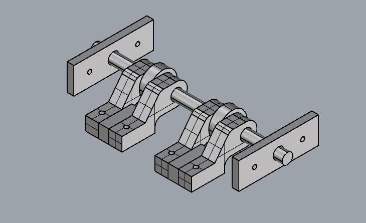
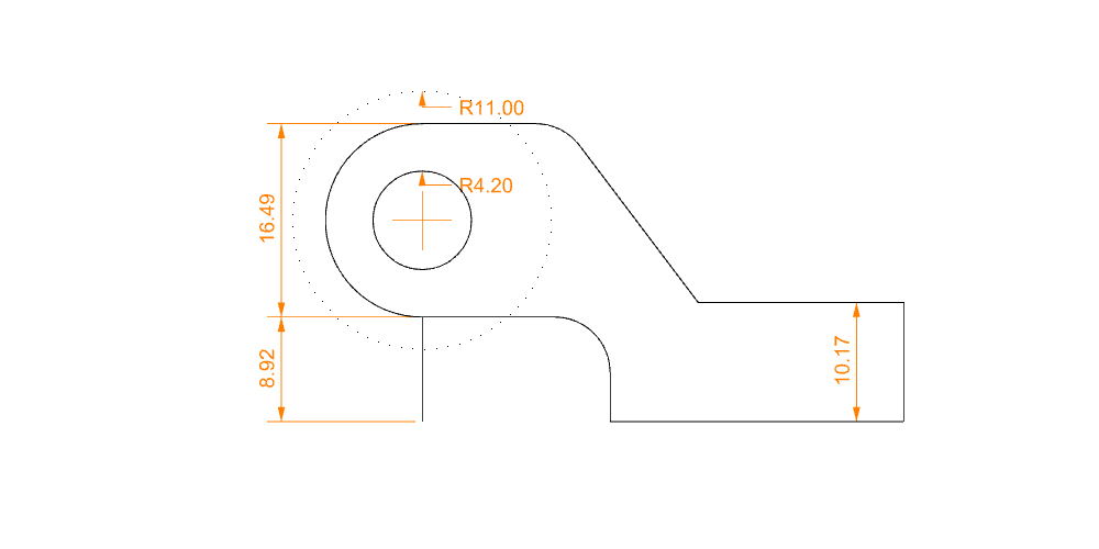
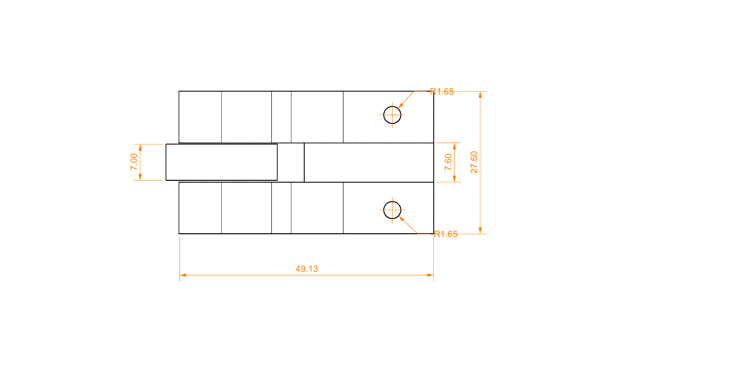
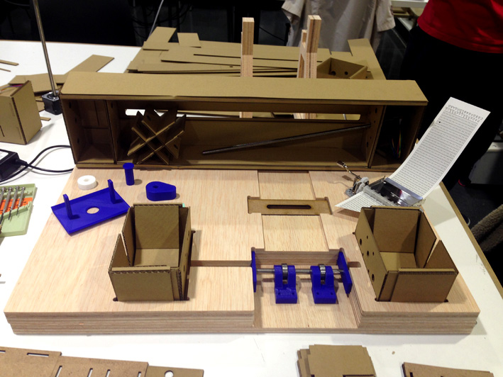
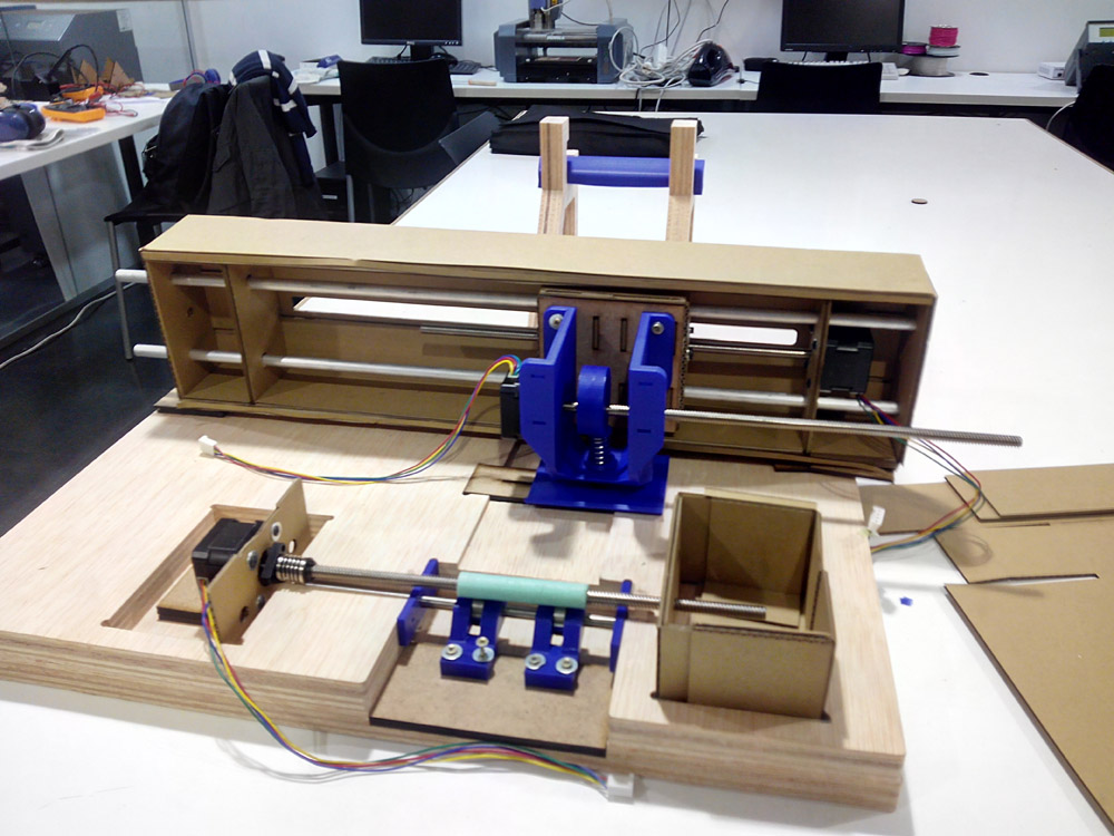
--- 4. Design and assembly of parts in 3D printing. ---
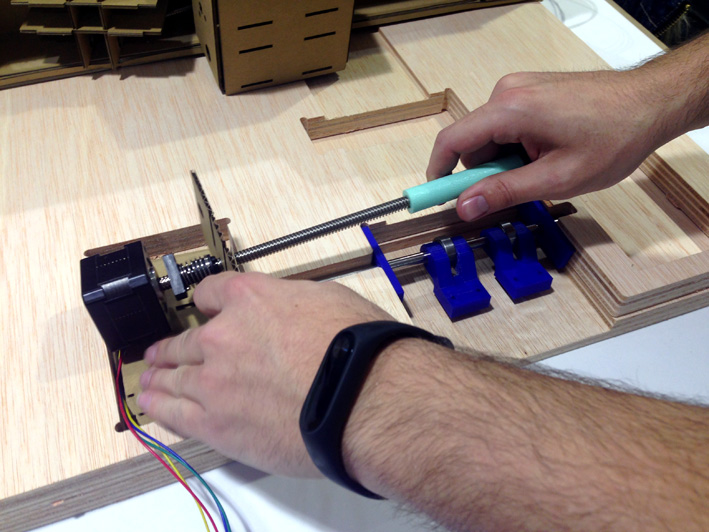
PLA rod holder
For the roller system we need a part that holds the rod where the bearings go, and allow the rotation of the bearings but not the lateral movement.
We considered the diameters of the bearings and the rod.
We also added a screw anchoring system ,we design and print the object in 3d.
Settings:
Software- Makerbot
Temperature:205?C
Supports-No
Raft-No
Infill-25%
Problems:
The main problem was with the 3d printer and the PLA temperature, we need to send three times one of the objects.
Software: Rhinoceros 5.0, Makerbot
Hardware: Makerbot replicator v2.0
FILES:
design files in 3dbase here the STL.--- 5. 3D integration of the machine, artwork and drawings. ---
I have been chosen to make a 3d model where all the components placed in its place appear, and take the order of the placement of the components.
When someone was designing a new piece, I would upload it to the cloud in stl or 3dm format and I was in charge of placing it and adapting the base placement of those pieces.
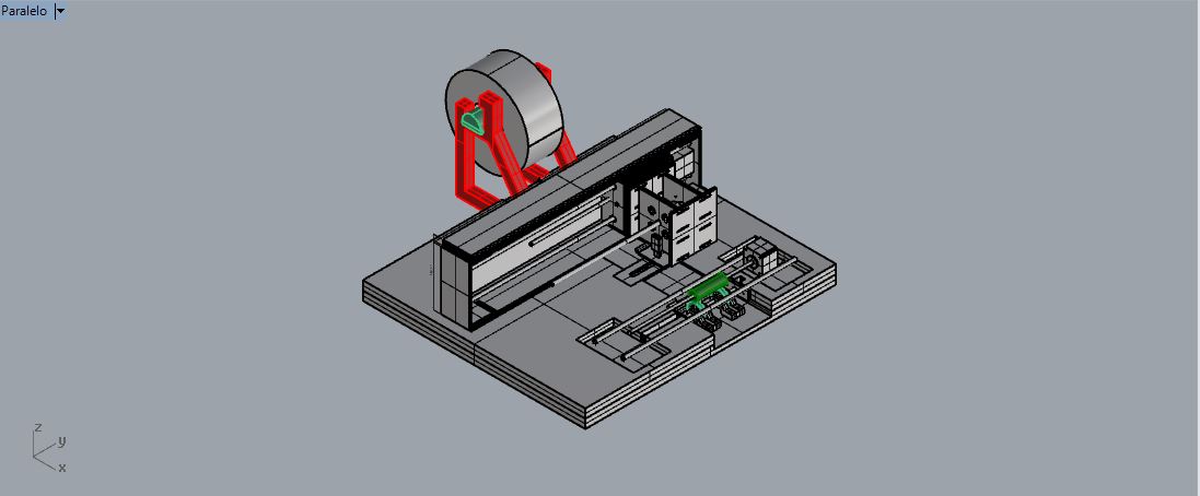
the whole 3D design.
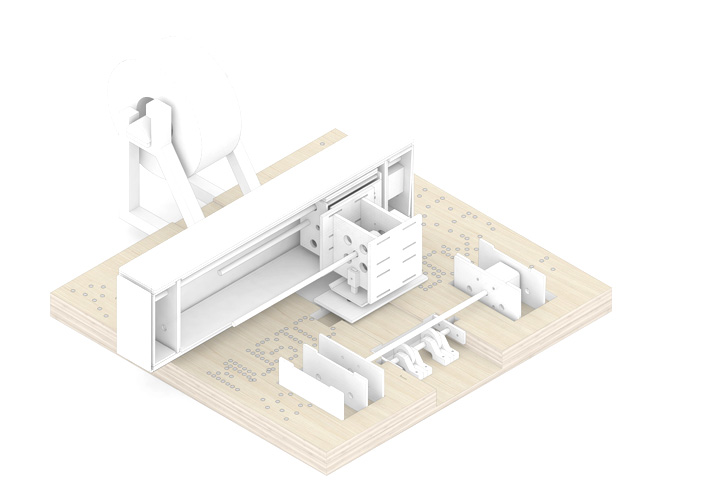
Artwork, a render with textures.
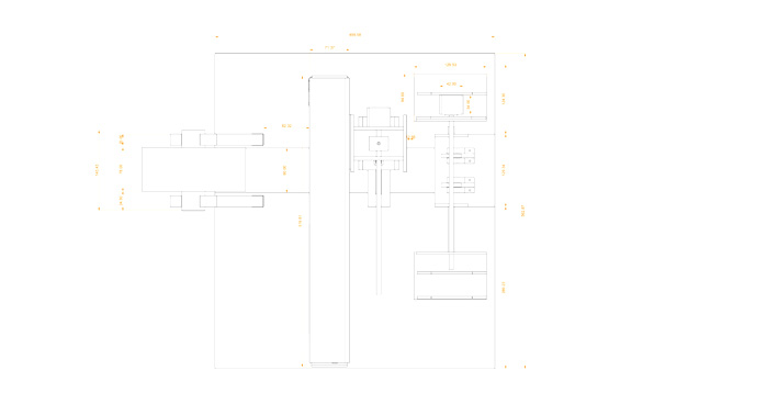
fabrication plans
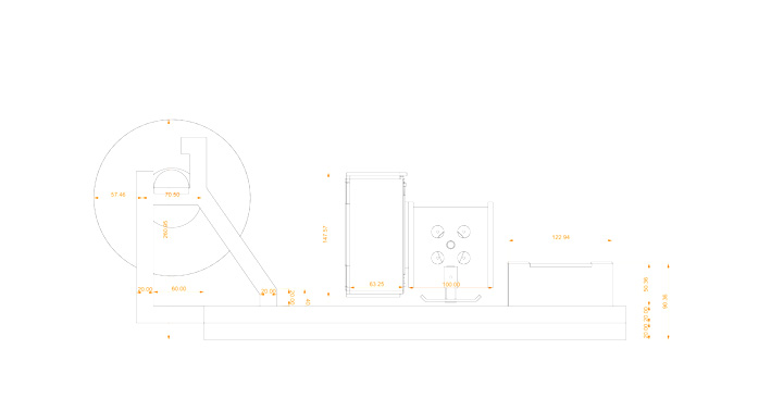
Elevations
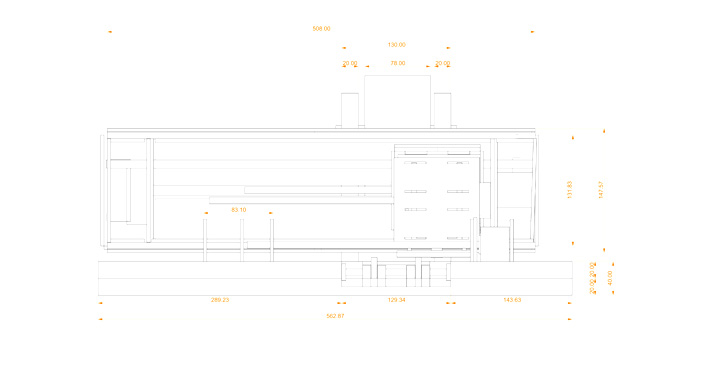
Elevations
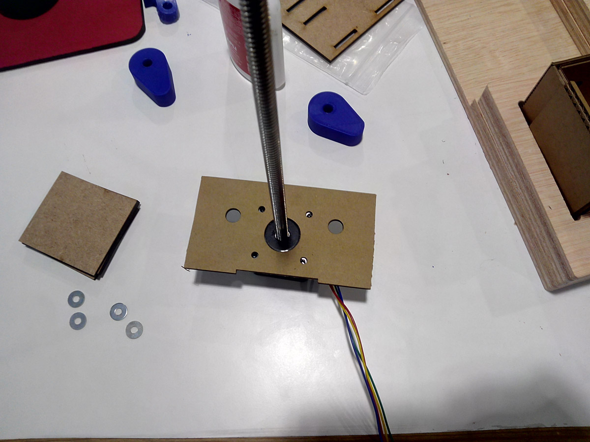
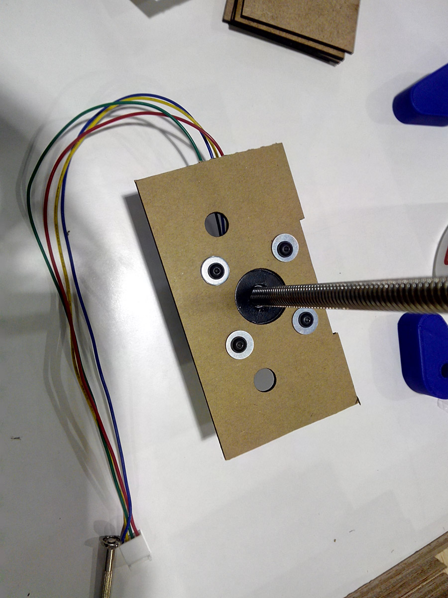
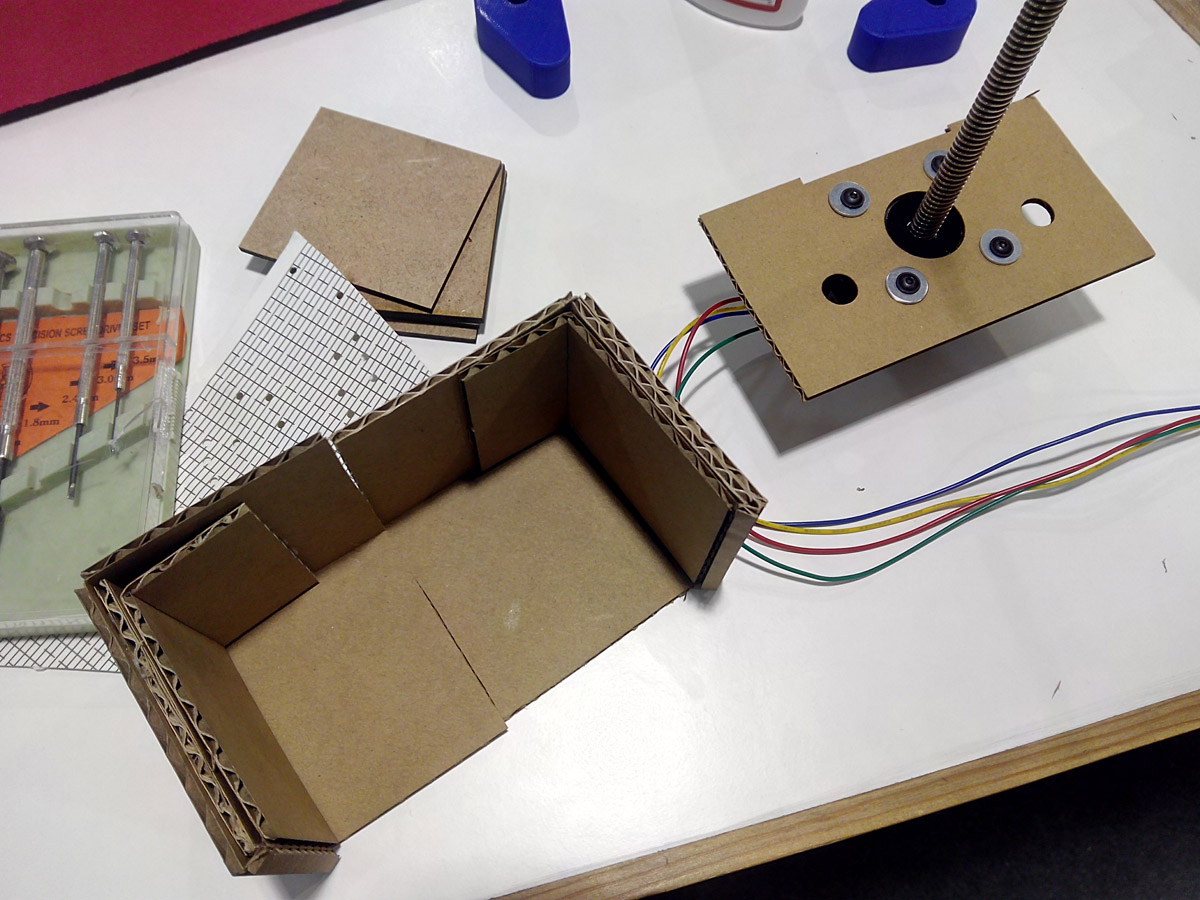
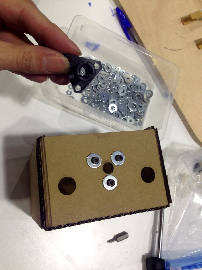
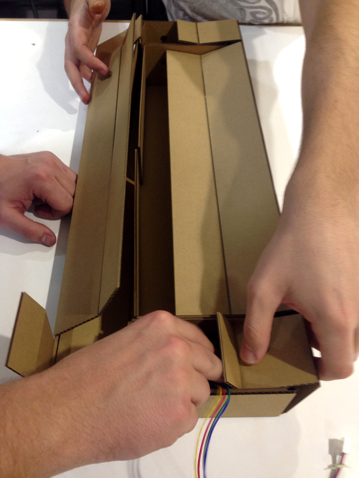
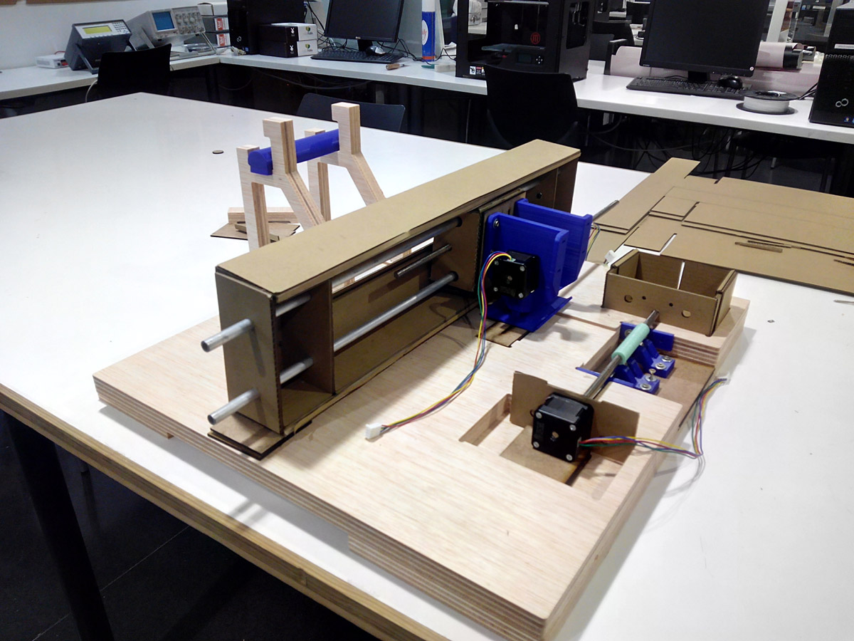
--- 6. Engine housing ---
For the roller that moves the paper sheet, we need a housing to hold the motor, I made a toolpath to the base so that the motor shaft together with the coating was at the same height as the bottom roller, and the casing was made with separate stage parts.
Software: Rhinoceros 5.0
Material: 3mm Cardboard
Re-Design plans of the box
Cut in the laser cutting machine with the same parameters as the stage.
the whole 3D design.
You can find this part of design in the file of redisigning stage.
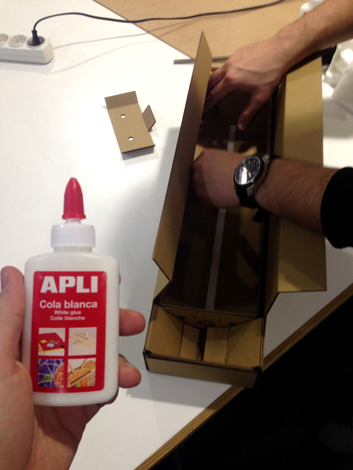
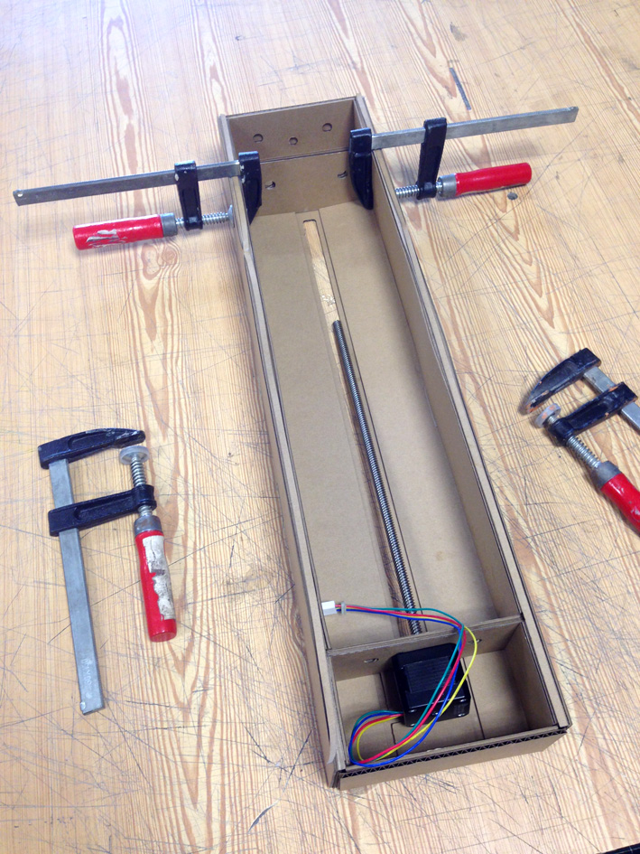
--- 7. Assembly, sanding, screwing, gluing .... ---
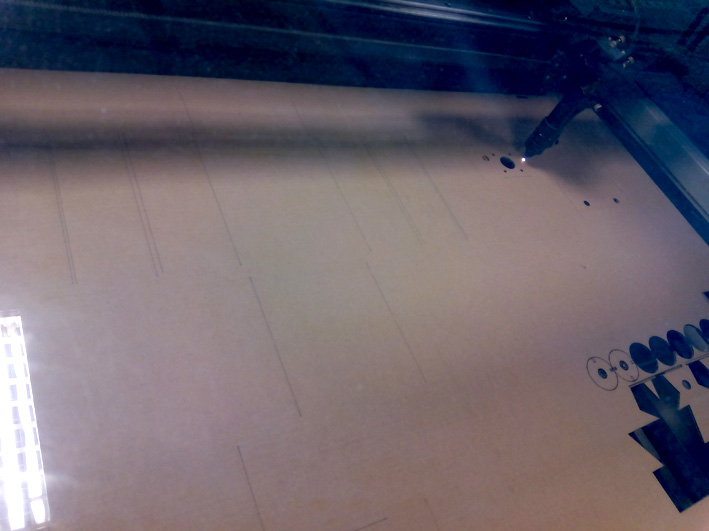
--- 8. Engraving the base with laser cutting machine. ---
ENGRAVE:
As decoration I wanted to give a personal way to our machine, I made a design to engrave the wood base in the laser cutting machine.
The design I made with several images of scores, music diagrams, musical notes and introduced letters and names.
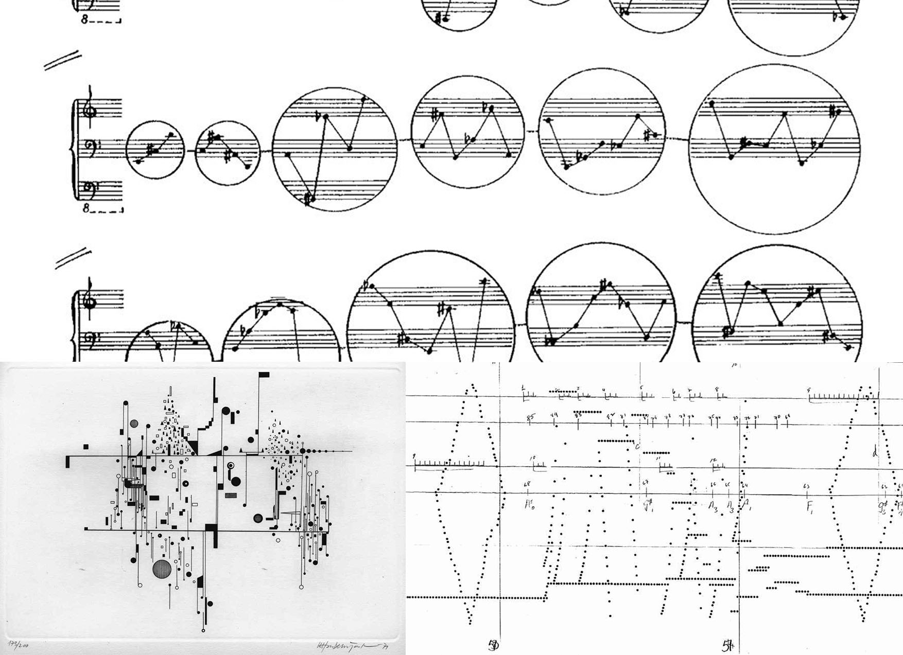
music diagrams
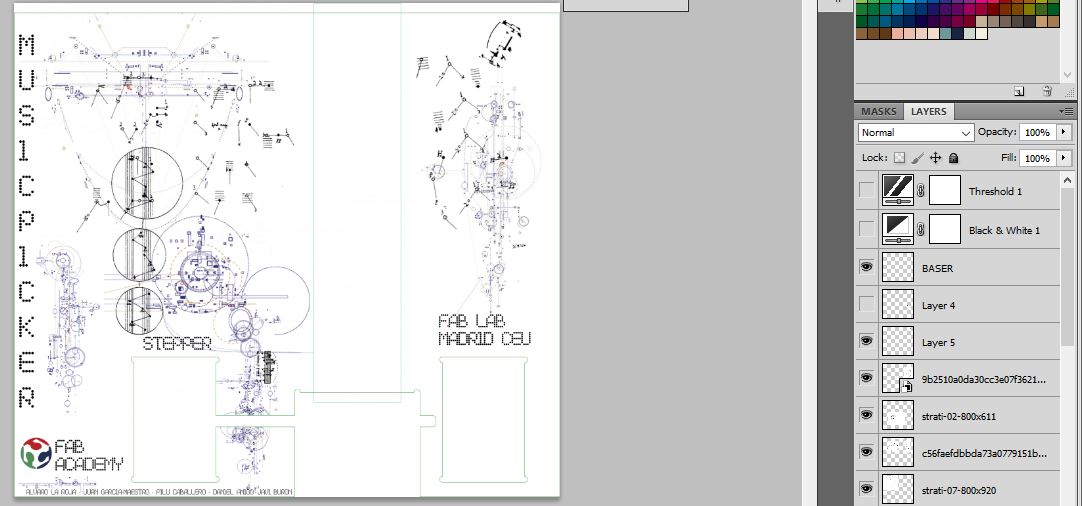
the collage with our design
black&white version
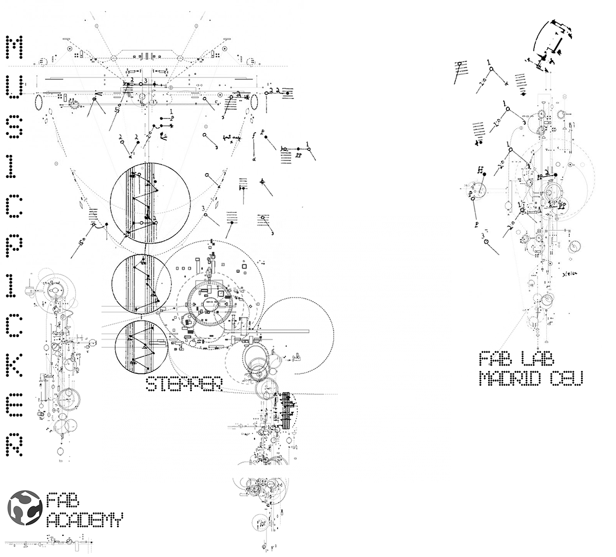
the bitmap image.
Here was a problem, was that when we went to engrave with this file, barely recognized the contours and were not seen well the engravings.
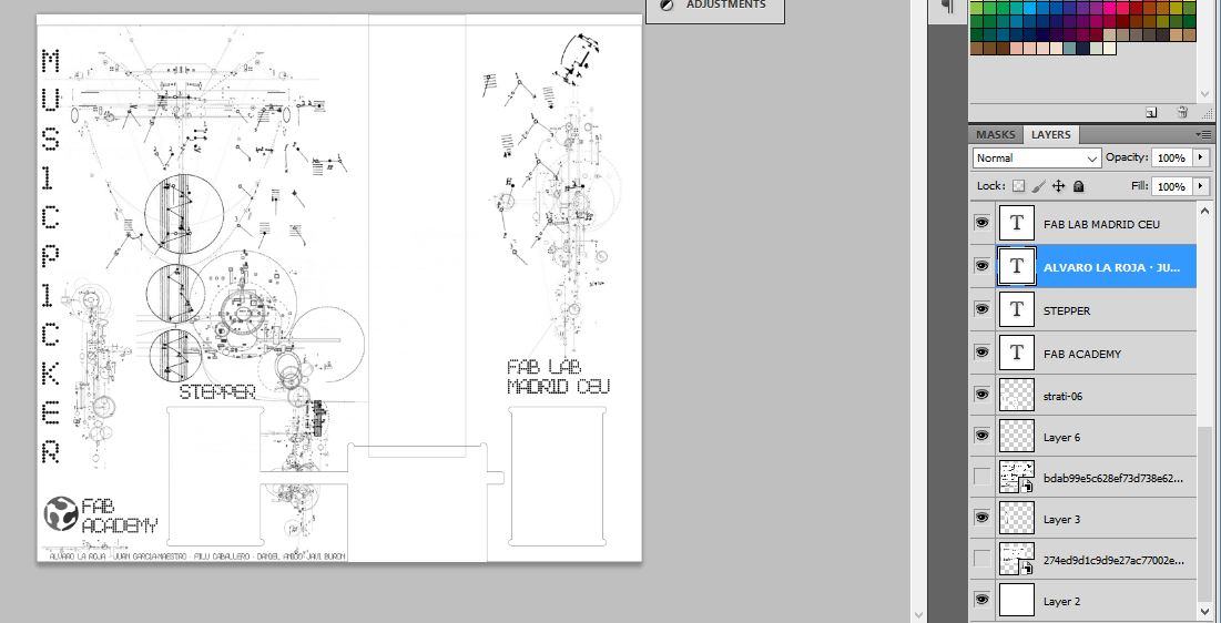
Solution, retouch the image in photoshop with the threshold tool:
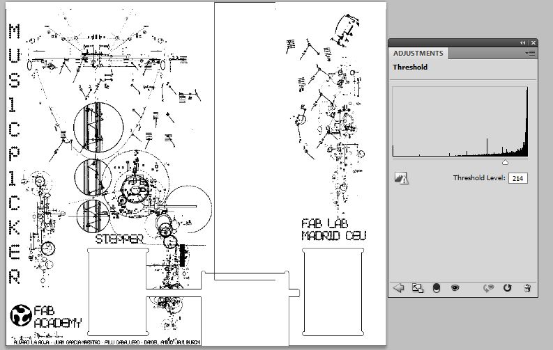
adjusting the threshold
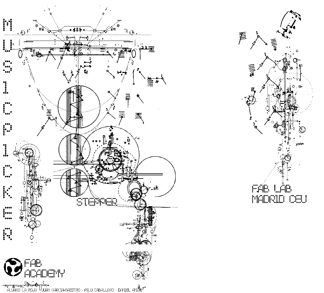
the image its more defined
raw
with threshold adjustment
Design files in the bottom.
--- 9. Making the Poster of our machine. ---
I have done it in illustrator, all the texts and the placement of the images.
Preparing the images from photoshop, making circular cutouts, and changing the tones and saturation to make them homogeneous.
finishing the logo in illustrator
The design does not have a concrete inspiration I have simply introduced all the images and the different methods of manufacture ordering them.
the result
Design files in the bottom.
the panel design has a considerable size because it has many linked images and the files in illustrator weigh too much, I uploaded the file without the linked images where the panel design is seen without linked files.
--- 10. Make a good Logo ---
I have done it inspired by the following logo, and from 2 images taken from flaticon very simple.
This is the first, it is an arm of a laser machine.
you can download from flaticon
This is the second, that is a kind of flying paper.
you can download from flaticon
This is the result of the two images converted into photoshop.
The mix of two images.
The final logo I designed it in illustrator putting the text along a curve, in this case a circle, and putting the background that we used for the slide.
finishing the logo in illustrator
The result