Assignments:
- Make an in-circuit programmer by milling the PCB, then optionally trying other processes
- Programming
For this assignment I have had to try harder to go slower than with other assignments because:
- I have never studied an electronic circuit,
- I have never soldiered
- I have never programmed a circuit.
WORKFLOW:
1. Learn how to use the machine Roland Mill MdX-20.2. List the components
3. Practice with broken components from the lab.
4. Milling the board
5. Stuffing the board.
6. Programming the board.
1. Learn how to use the machine Roland Mill MdX-20.
1. The first step was to learn how to use the machine Roland millMDX-20 that we will use to record and mill an electronic circuit.
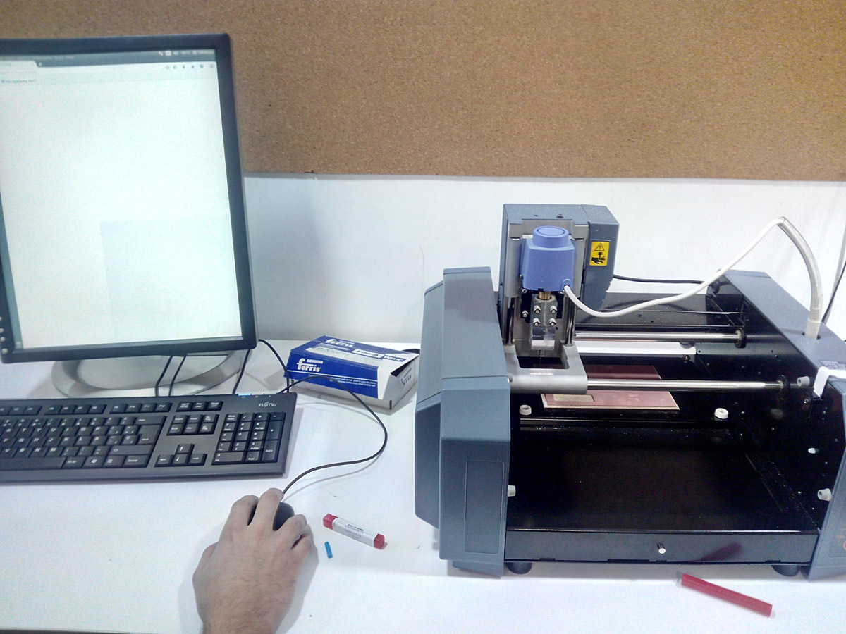
The machine and server.
The instructor taught us how to use the machine, how it works and the safety measures to follow.
Be very careful when handling the milling cutter, as there is little space and the tip of the milling cutter is very fragile.
I made a list of the the components that were necessary for the following tutorial.
FAB ISP :
2. List of the Components:
- 1 ATTiny 44 microcontroller- 1 Capacitor 1uF
- 2 Capacitor 10 pF
- 2 Resistor 100 ohm
- 1 Resistor 499 ohm
- 1 Resistor 1K ohm
- 1 Resistor 10K
- one 6 pin header
- 1 USB connector
- 2 jumpers - 0 ohm resistors
- 1 Cystal 20MHz
- two Zener Diode 3.3 V
- one usb mini cable
- one ribbon cable
- two 6 pin connectors
3. Practice with broken components from the lab.:
It is the first time that I solder, therefore I had to practice a lot with boards and reused components of the ones that we had to practice, and then to make the Fab ISP correctly without breaking the materials.
preparing the board for soldering.
First attempts at soldering.
Components are very small.
This is the preparation of my workspace:
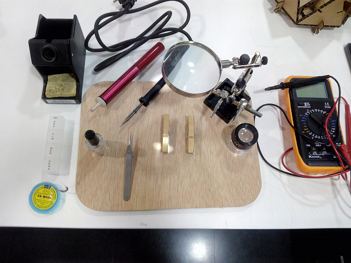
Its so tidy...
My tools:
-soldering wick or braid
-Tweezers
-Flux
-weld wire
-10x loupe
-Magnifying Glass
And these are some of the earliest soldering attempts.
4. Milling the board
Follow these steps:
- Turn on the machine and bring the carriage to the origin,
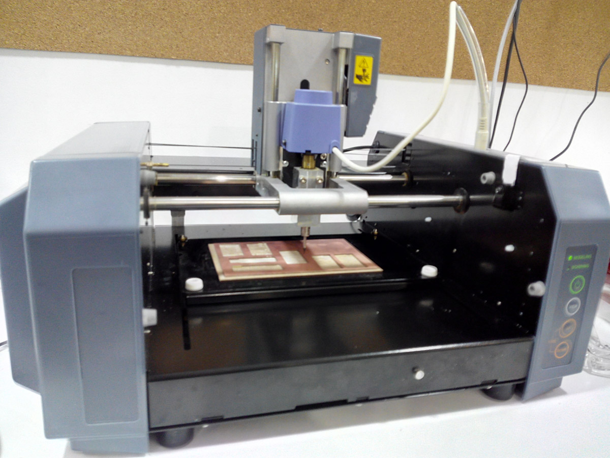
The milling machine Roland Mill MdX-20.
- Change and place the milling cutter on the spindle.
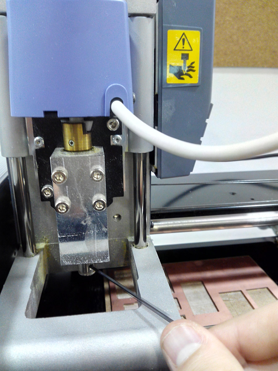
adjusting the cutter.
- Place the cutter on the z axis near the plate to be engraved.
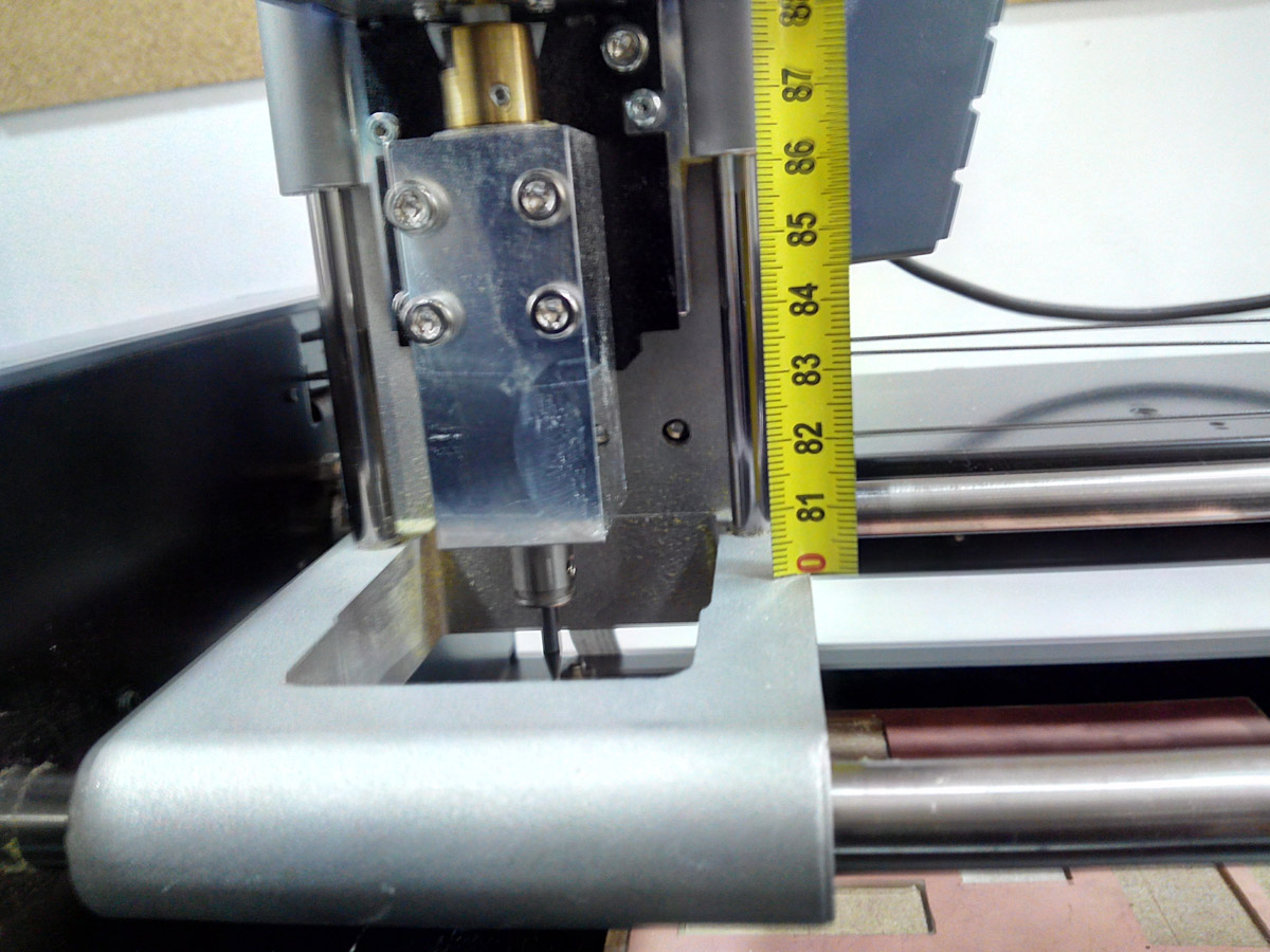
Lowering the cutter 5 mm from the stop for safety.
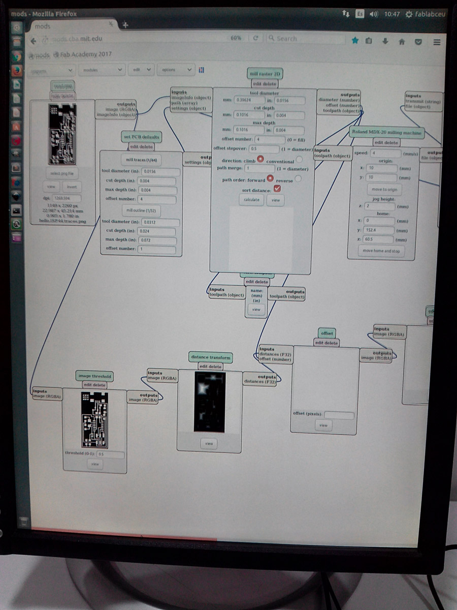
- Go to mods.mit.edu etc and choose our machine, start to choose the parameters with which we want to work, our type of milling cutter, the offsets that need to be done, the origin ... etc and point the origin.
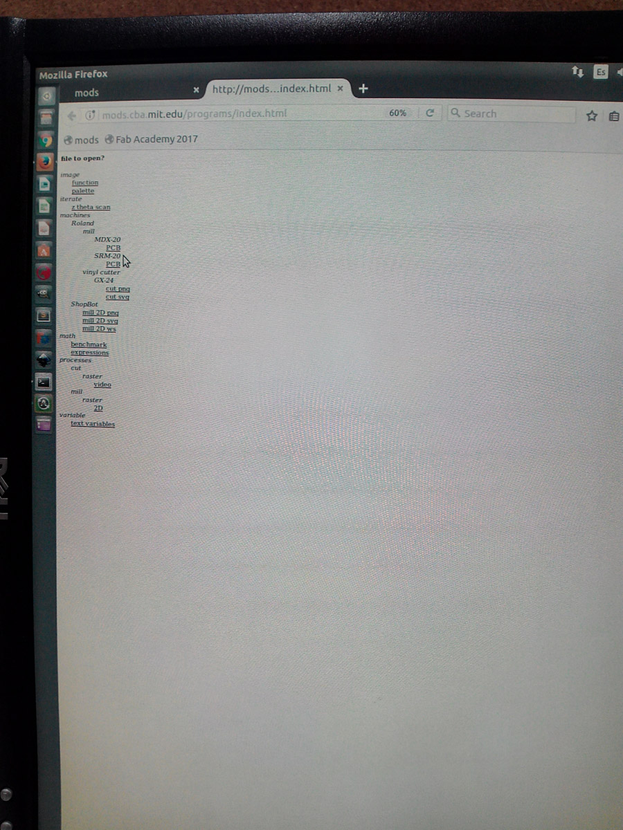
select our machine.
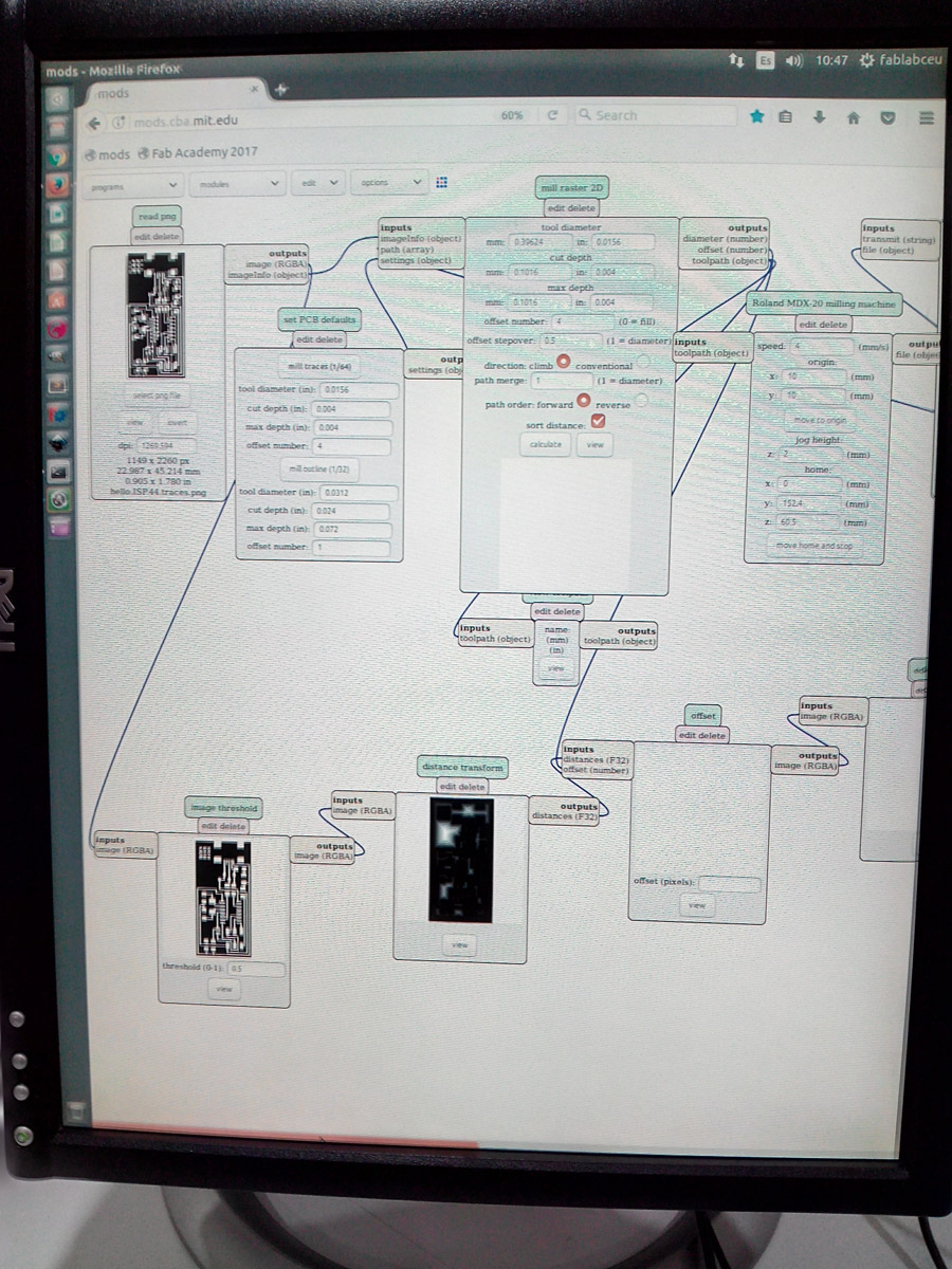
setting up the preferences and milling traces etc...
- Then we will again loosen the milling cutter and let it fall gently in until it makes contact with the board, once contact will press and hold the prey and we will tighten the fixture so that it is ready to record.
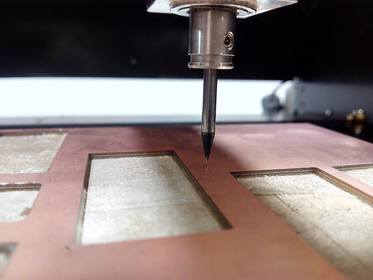
adjusting the cutter in contact of the board.
We upload the image that we want to record and we calculate the path, once calculated we send it, and the machine begins to mill.
Calculate.
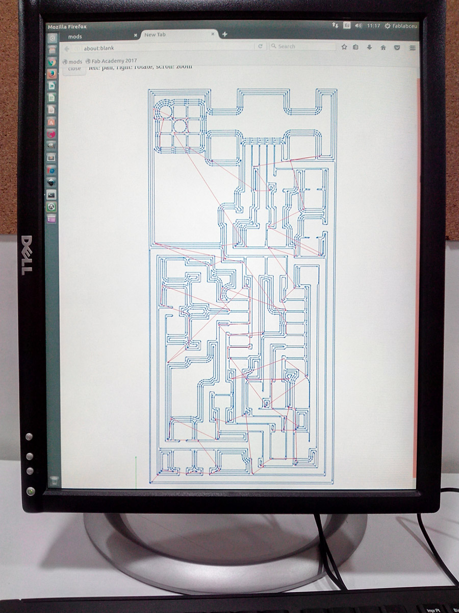
This is the path of the milling.
I will monitor the machine at all times if there is any problem pressing stop immediately
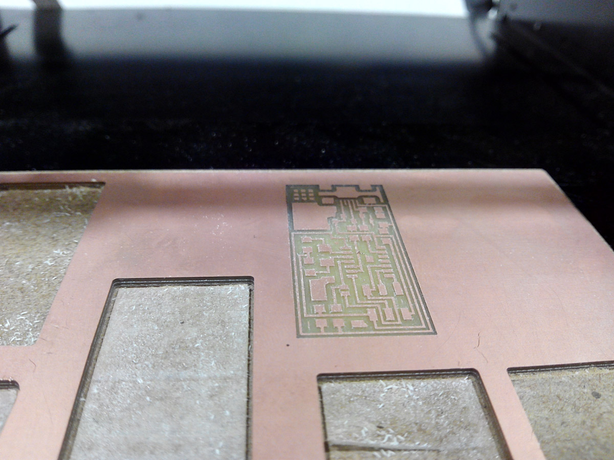
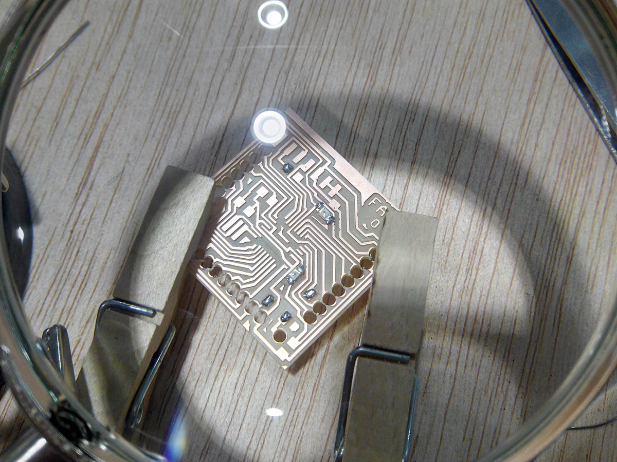
This is the result of the engraving.
We have to repeat the same process with the 1/32 milling traces and the exterior shape for cut the board.
Finally the board is extracted with the aid of a lever.
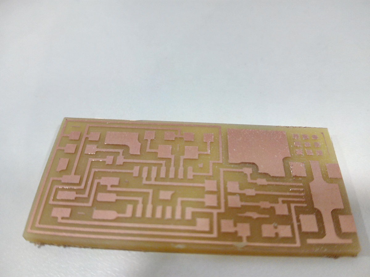
The board.
5. Stuffing the board.
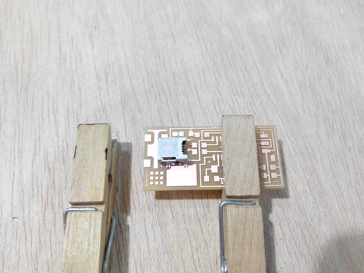
We will weld the components in the following order: 1. USB connector
2. ATTiny 44 microcontroller
3. Zener Diode
4. Resistors
5. Capacitor
6. Cystal 20MHz
7. 6 pin connectors
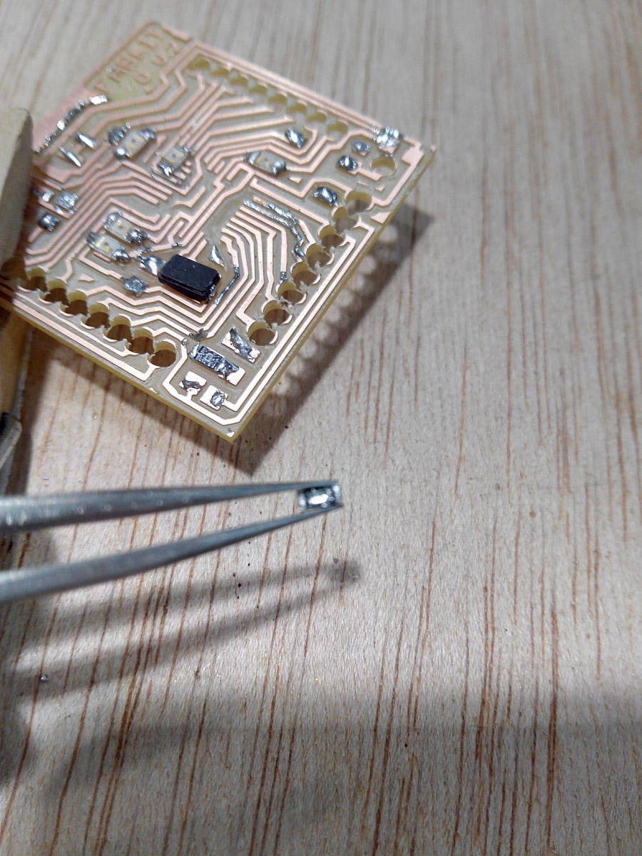
I held the board with tweezers.
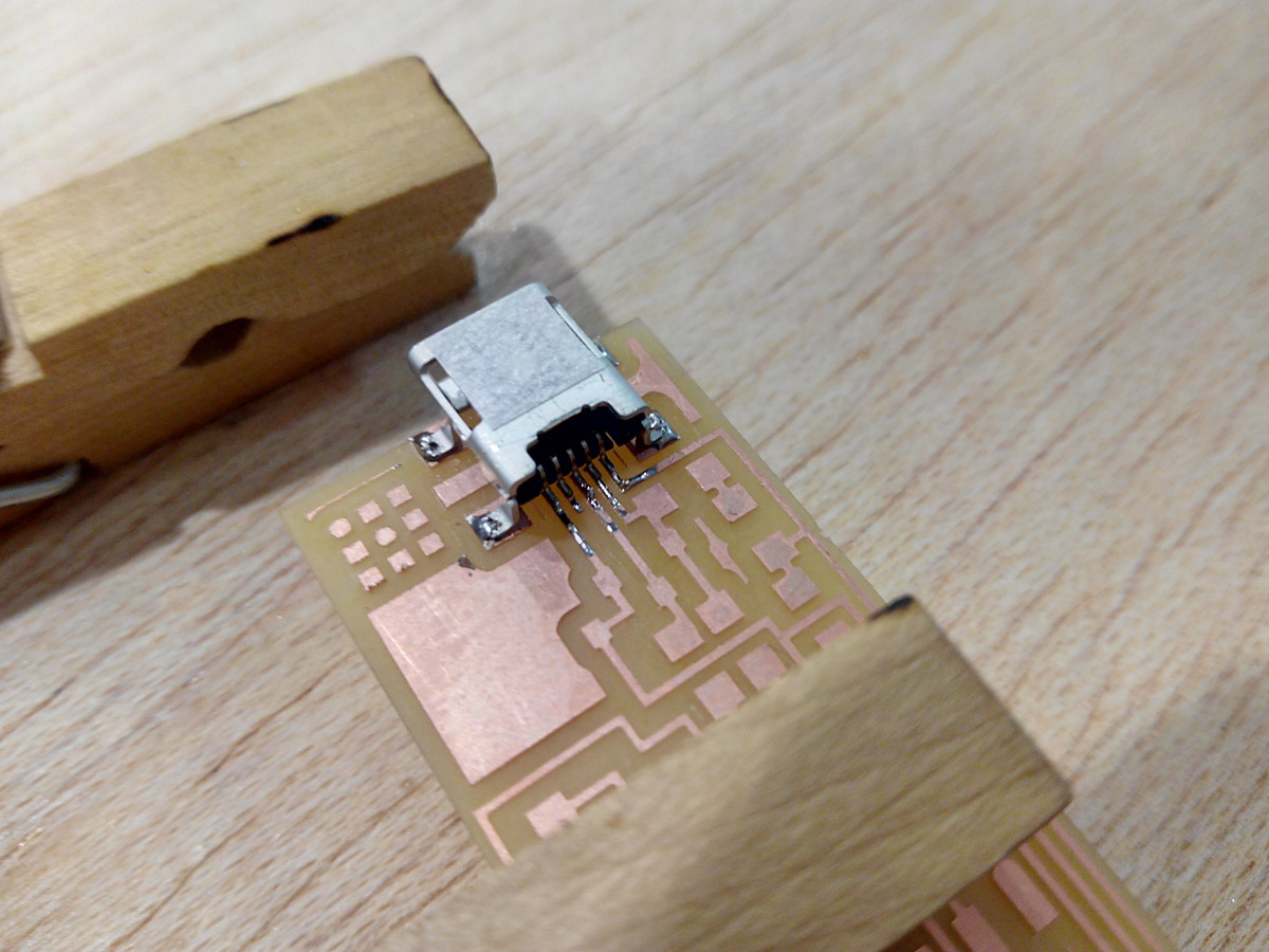
At first i soldered the usb connector.
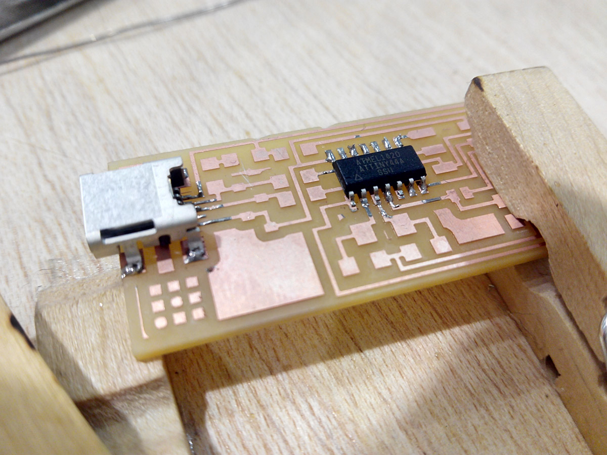
then the microchip.
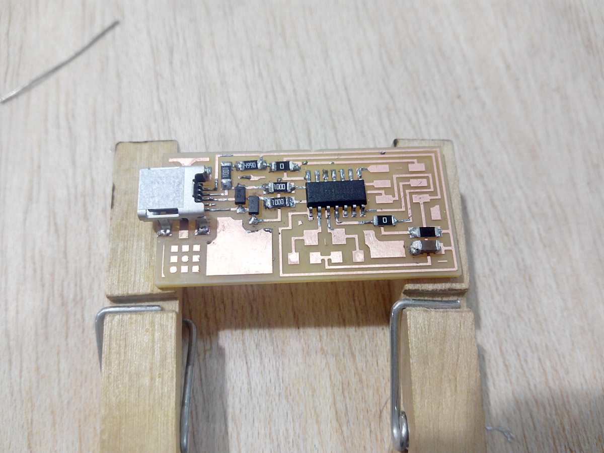
resistors and capacitors.
the 6pin conectors and crystal.
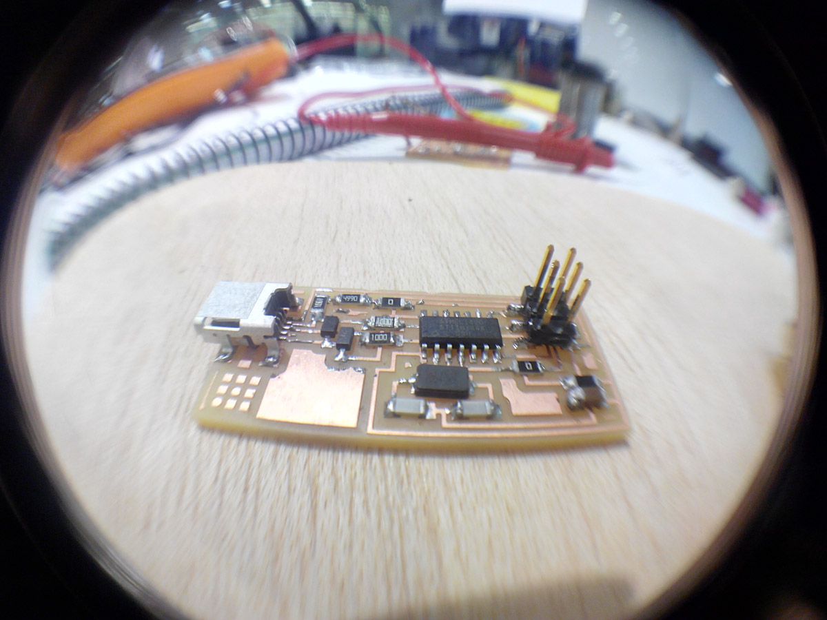
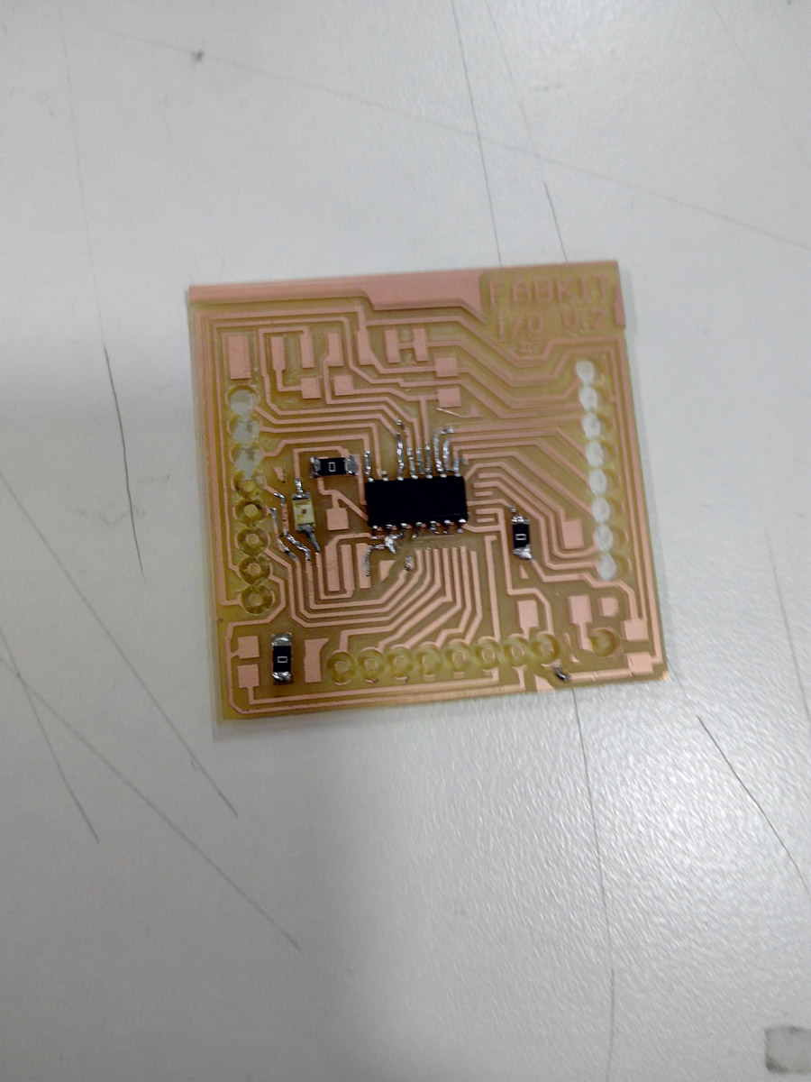
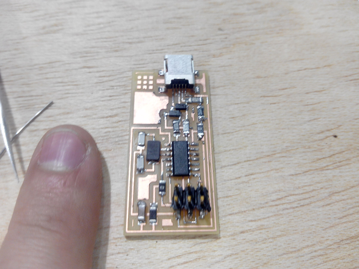
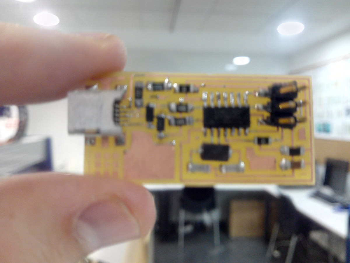
looks good.
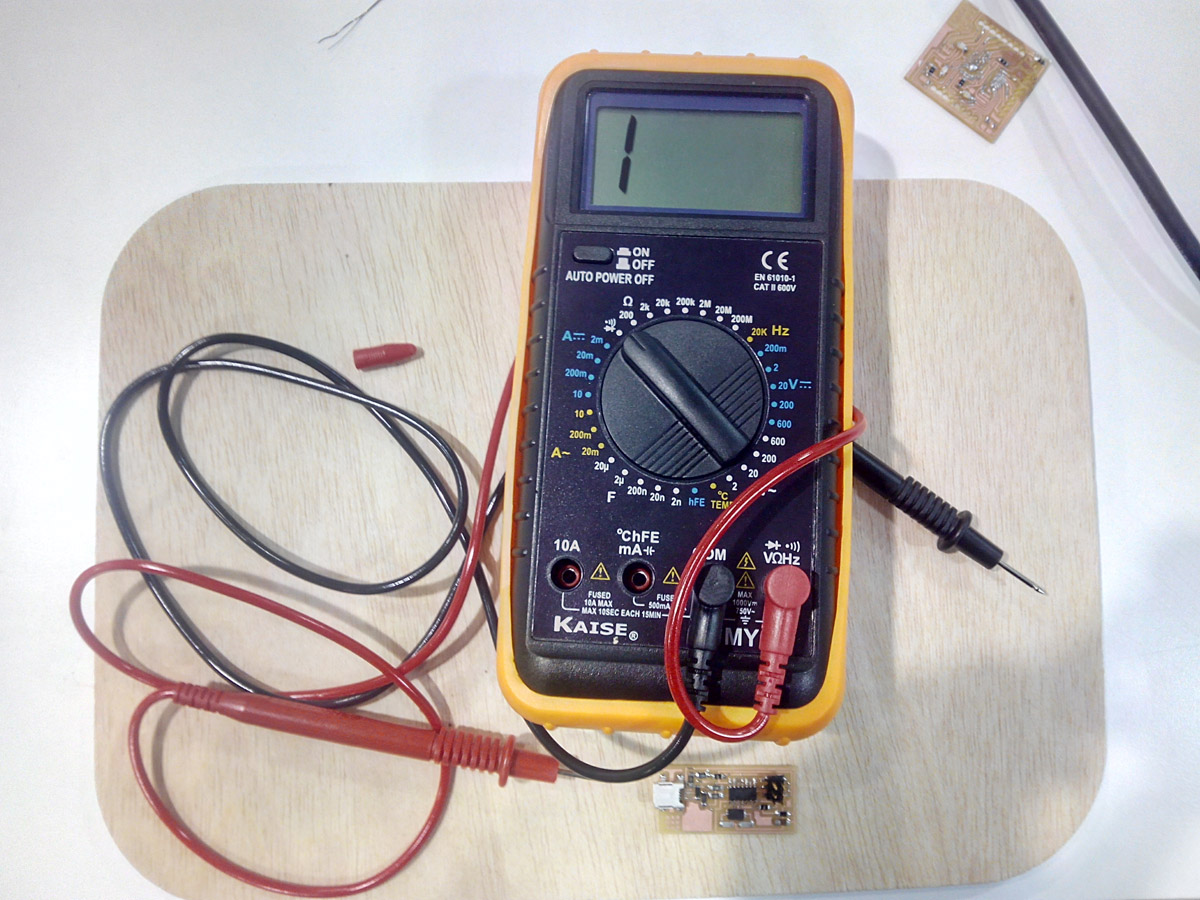
We will measure if everything is well connected.
There ar two connectors that didnt were soldered well in the microchip.
The components were re-soldered and all my board have electrical continuity .
6. Programming the board.
For the next part we will use the tutorial that comes here:
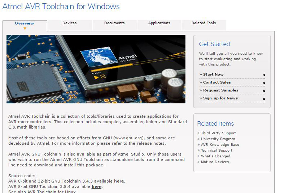
USING THE GNU AVR TOOLCHAIN IN WINDOWS 10
Problems, first to program my fab isp needed another programmer, that made me lose some time while following the tutorial.
Second problem, the S.O from my computer is old and works at 32 bits, so some programs like avrdude did not work following the tutorial.
I installed atmel GNU toolchain.
-Sparkfun schematic design tutorial Link.
And Avr Dude.
I updated the path by following the steps.
And doing a git bush in the folder of avrdude we make
The avr gcc and avr dude.
download.
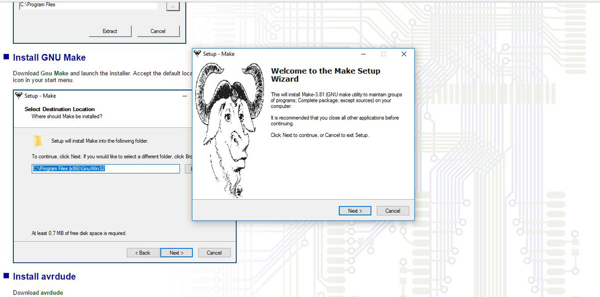
setup.
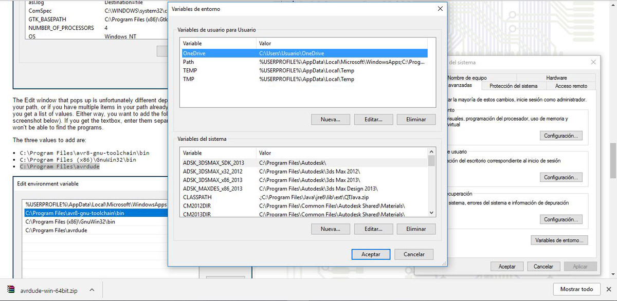
updating the path.
- This is the guide for programming FabISP
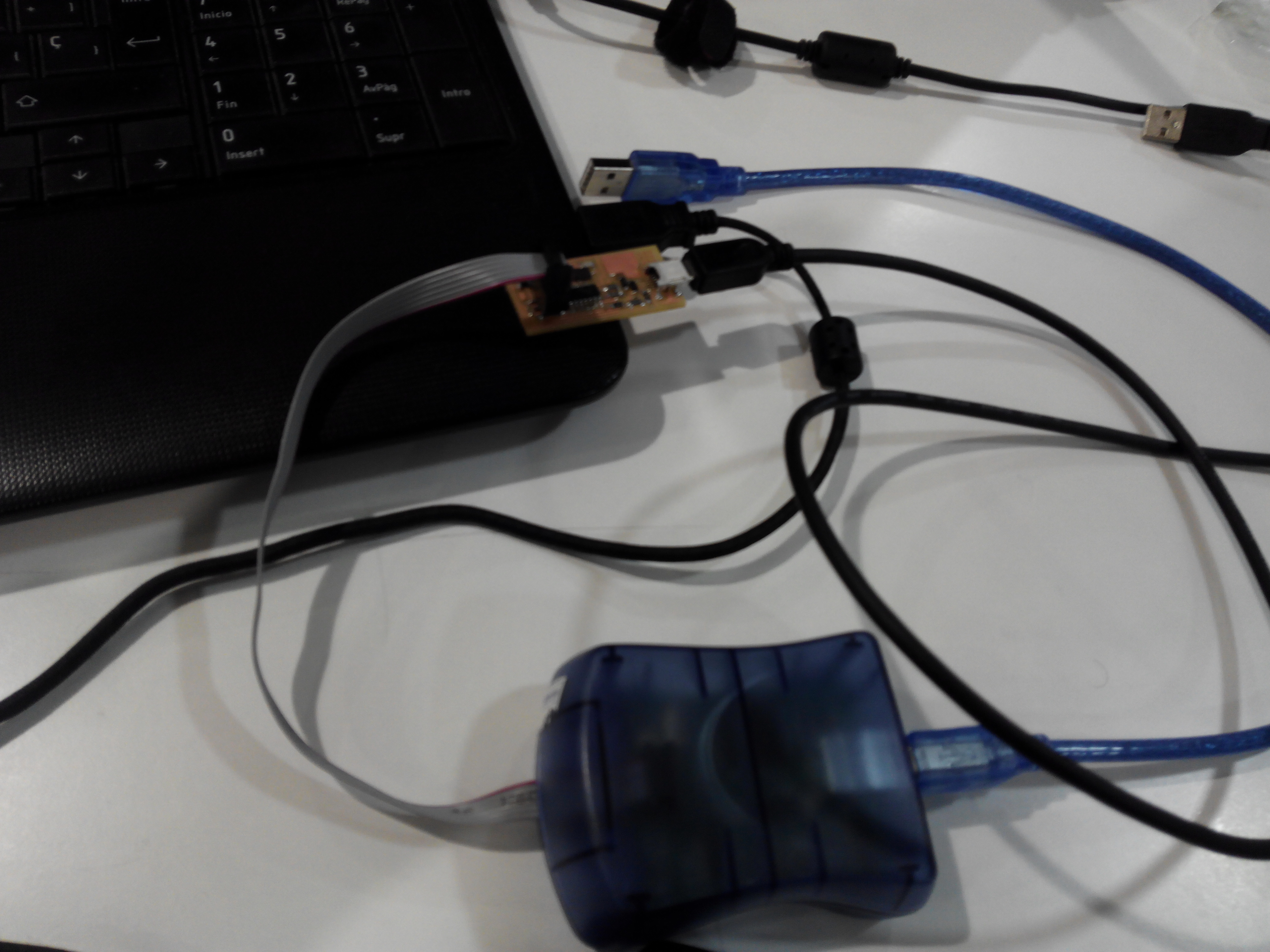
I needed to connect my PCB and the avrisp2 for transfer the bootloader to my fabisp.
I had to download the firmware.
avrisp
Then I have to programming in Zadig
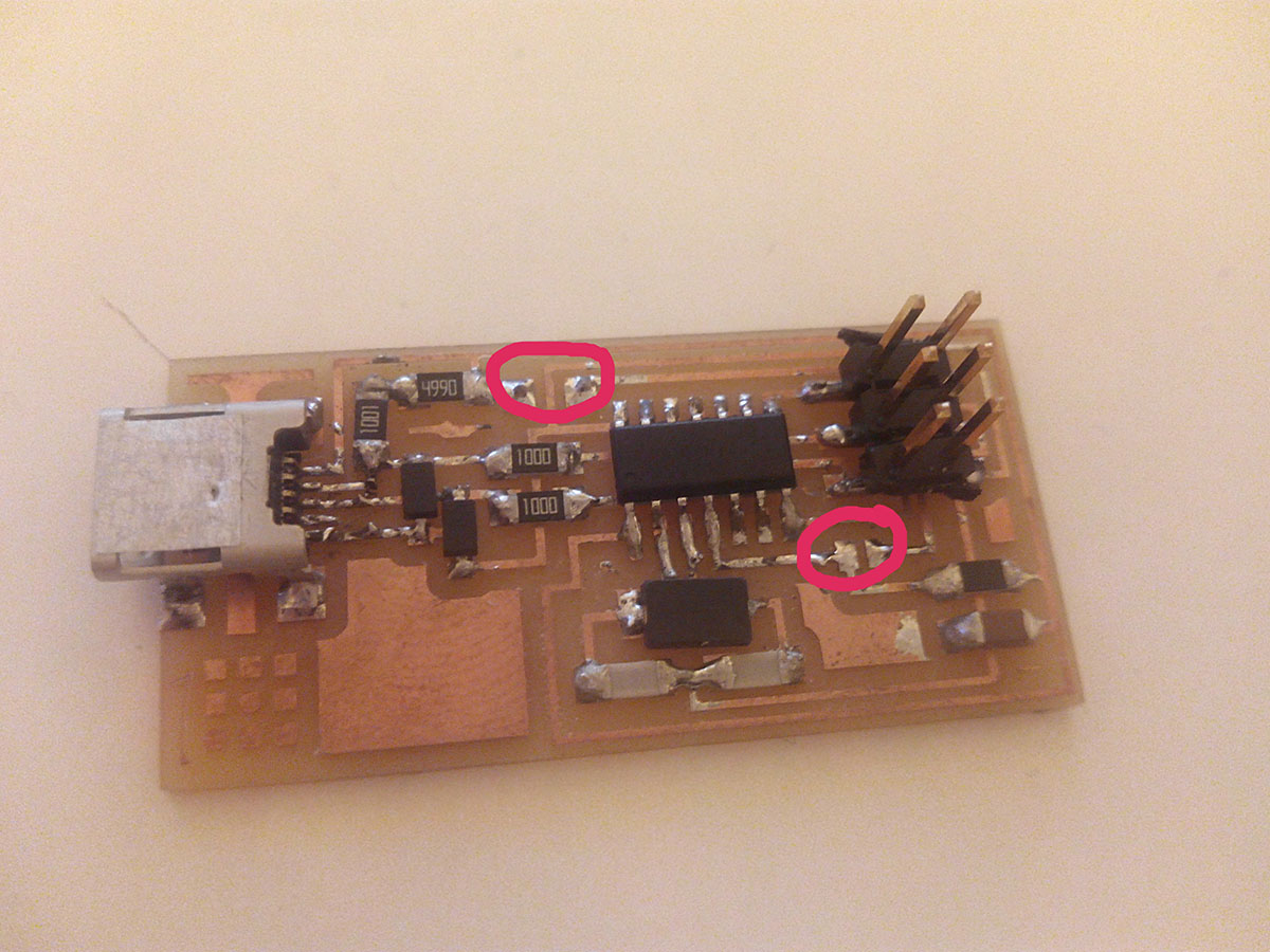
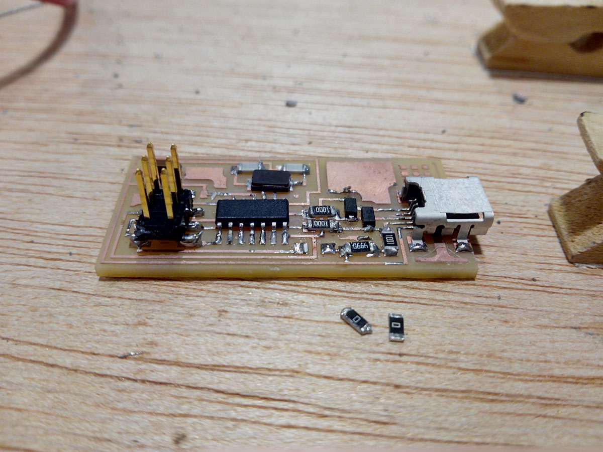
In order to enter the drivers from zadig I had to unsolder 2 jumpers.
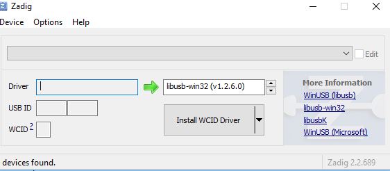
zadig
The drivers has installed succesfully!
and open the Git:
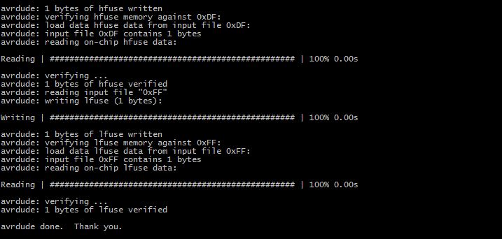
Finally I did git bash here and wrote: make clean, make hex, make fuse and make program.
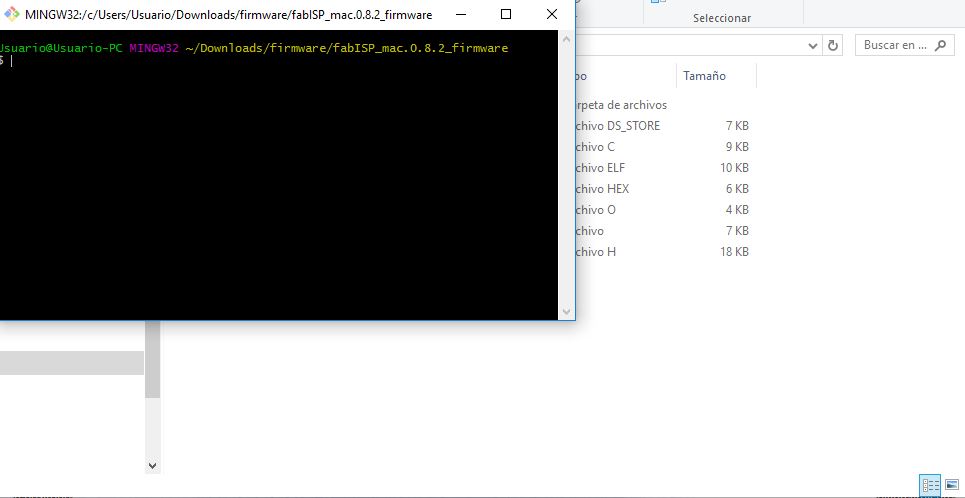
open GIT
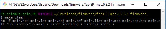
make clean
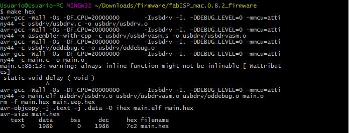
make hex
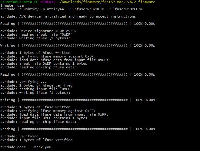
make fuse
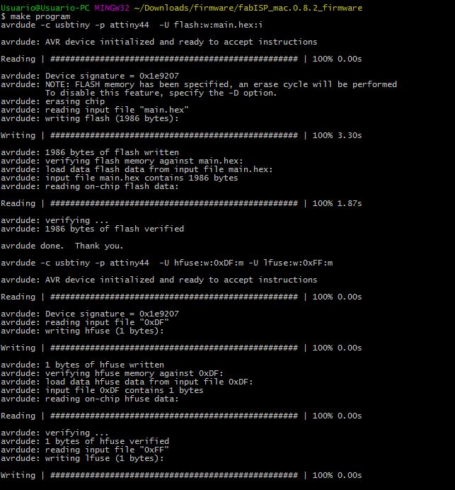
make program
Thank you!
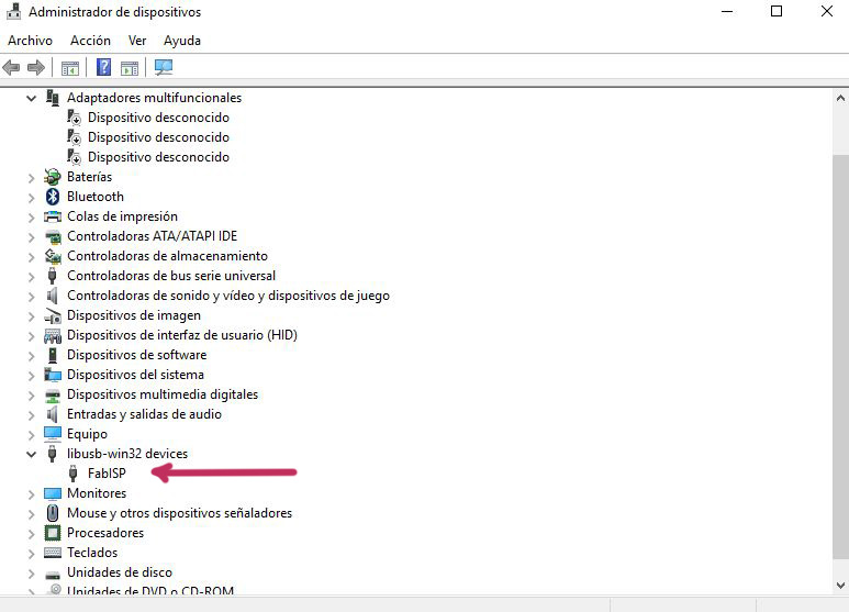
My computer recognizes fab isp in device manager
The Fabisp programmer verified that it worked when in exercise 8 I programmed the helloecho board.
Preparing the fab isp to programing
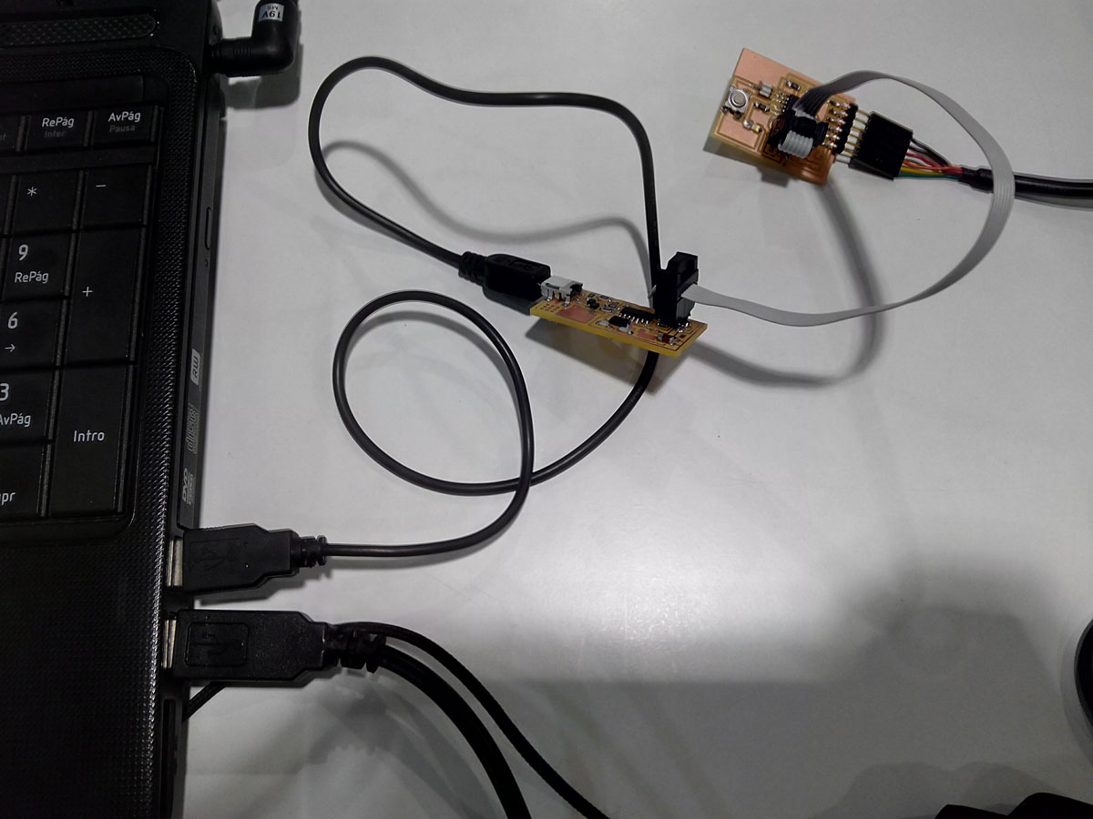
Connecting the fab isp and the hello-echo at the laptop

My Fabisp Works as programmer
LINKS USED:
Using the GNU AVR toolchain on Windows 10
-Sparkfun schematic design tutorial