So after completing networking and communication (week 16), I had a clearer idea what my final project would do. When you make wine, there are operations which may be necessary which cause air to be introduced into the wine tank. Air, or more specifically, oxegen, causes wine to spoil and creates wine faults. In order to explain the utility of my device, I must first explain some winemaking basics, and at what stages the device becomes useful.
Air inside of a fermentation tank is not much of an issue, because the tanks are usually filled nearly to the top with juice, and the remaining air in the tank helps the yeast get started. Once fermentation is started, the yeast consume all of the oxygen available, and then once all oxygen is consuimed, the yeast start to metabolize sugar into carbon dioxide and alchohol.
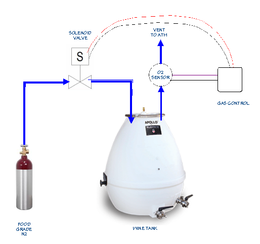
Once fermentation is complete, the dead yeast is allowed to settle to the bottom of the tank. Next, the wine is racked off, where the clarified wine is either siphoned or pumped leaving the dead yeast behind. The racked wine must be placed into a second container. This container is usually of equal size to the first container, and is full of air. There is usually a reduction of volume of 10% due to the sediment left behind. This "headspace" affects wine quality during aging. Some winemakers will take the trouble to purge the space with carbon dioxide or food grade nitrogen. Having a device which can measure oxygen level during purging is beneficial because you are no longer guessing. Furthermore, you can monitor during the aging process with the same device.
Simple device which replaces the traditional air-lock on a wine storage vessel. Must have the ability to monitor oxygen level and control flow of nitrogen gas, programmable, and remotely accessable. Skillsets used in this design are communications and networking, computer-aided design, 3-D printing, electronics production, output device, input device, application programming.
Some components which are not in the FabLab inventory were required for this project:
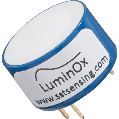
Cost: apx $90. Available from manufacturer, or from Amazon UK.
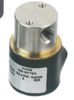
Available direct from manufacturer, or on Ebay for around $35.
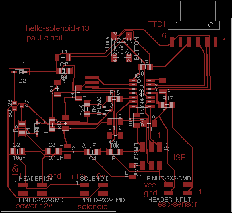
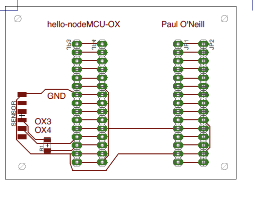
The Hello-Solenoid board is a descendant from the project we did on Week 8. This is a better version which addresses some of the failures of the earlier project. Designed using Eagle version 7.70 (Mac).

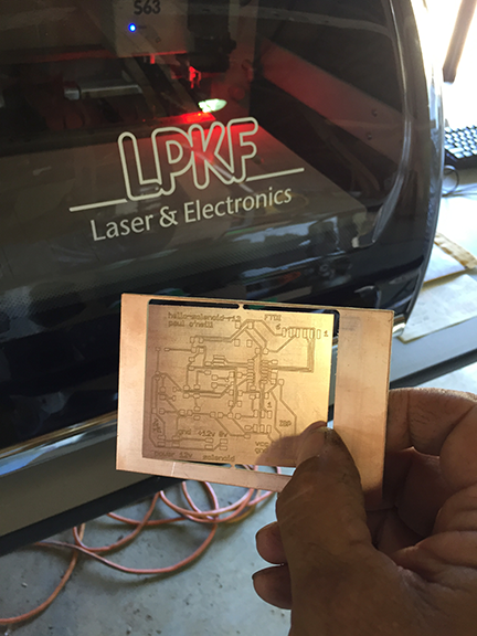
Convert Eagle file to Gerber file and cut on my LPKF board mill.
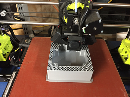
3-D Print hello-solenoid case on my 3-D printer. (file)
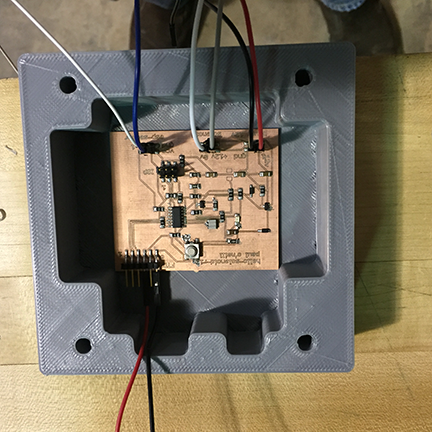
Hello-solenoid installed into case.
Note: Resistor R1 is a zero-ohm jumper.
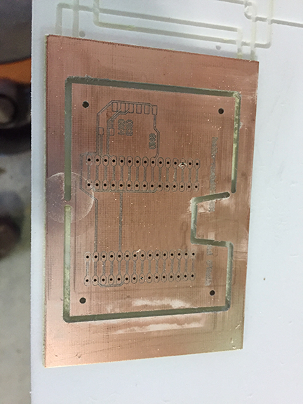
Board engraved and drilled on LPKF mill.
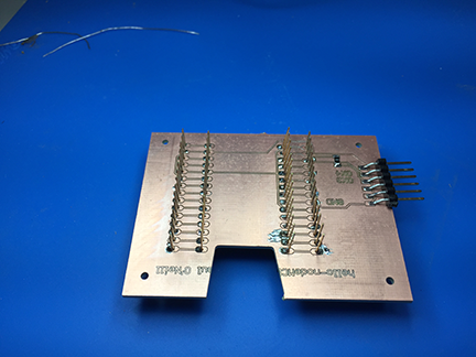
Header pins inserted into drilled holes and soldered. You need 0.80 mm
drill bit to get close tolerance hole for solder to bridge between pin and board.
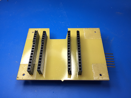
These type of header pins not found in FabLab inventory. You can find them
in the Adafruit git repository for Eagle CAD.
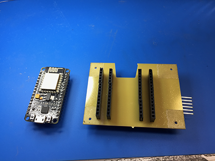
The nodeMCU before insertion intop the shield.
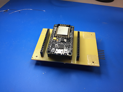
The ESP8266-12 nodeMCU installed into the shield. These can be bought for around $10.
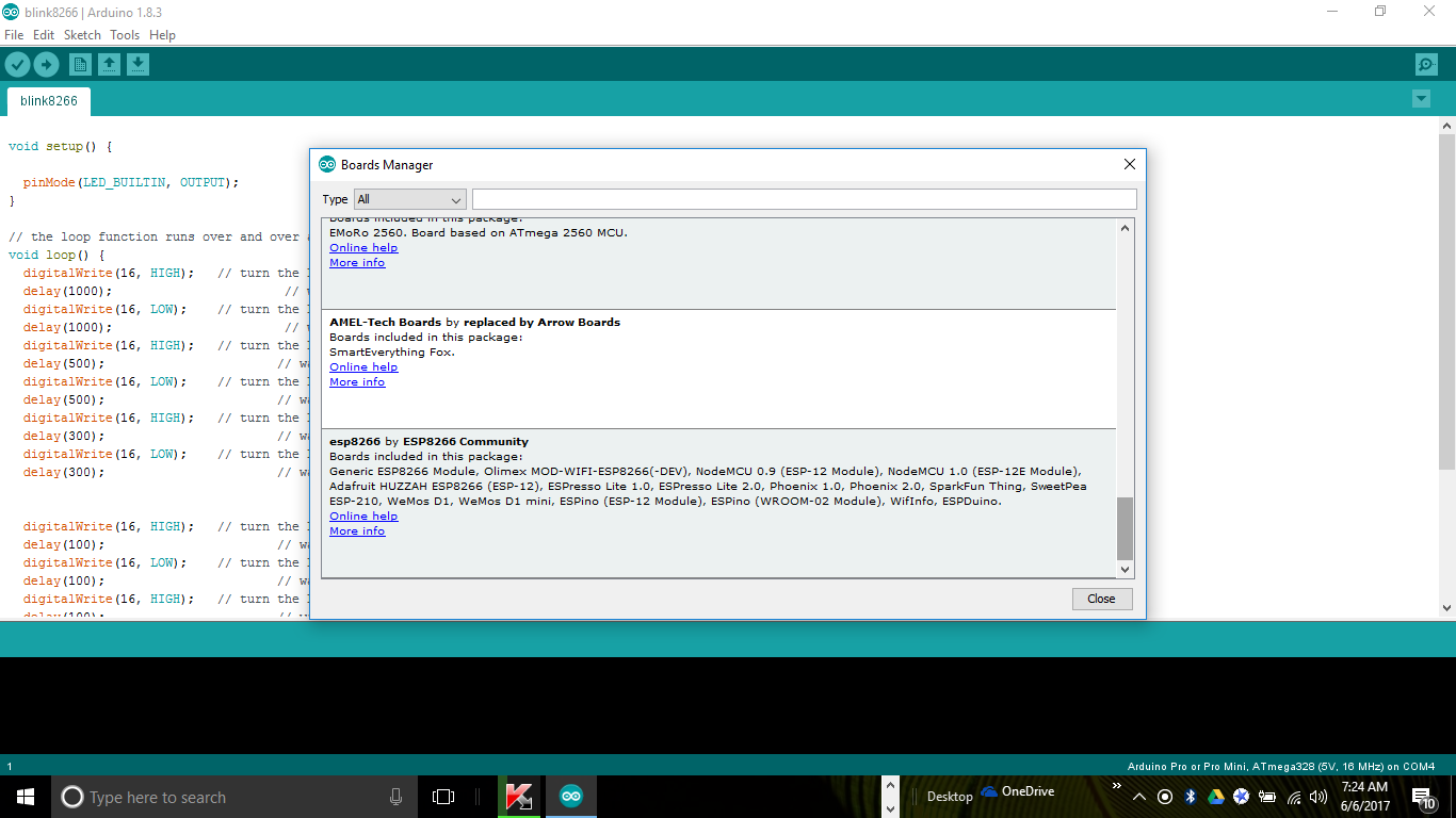
I used the Arduino IDE asd my programming environment on both a Macbook and a Windows 10 laptop. The Windows10 implementation is easier because ZCZZOM ports on the Windows machine are easier to tropubleshoot. You must add the esp8266 and ATTiny borads to the environment. You do this from the Arduino IDE main menu by drilling down Arduino - Preferfences - "Additional Boards Manager URL's" box -and click the shadow box to the right, enter the following into two seperate lines in the text box:
http://arduino.esp8266.com/stable/package_esp8266com_index.json
https://raw.githubusercontent.com/damellis/attiny/ide-1.6.x-boards-manager/package_damellis_attiny_index.json
Then go to Tools - Boards Manager and install esp8266 as well as ATMEL Tiny packages.
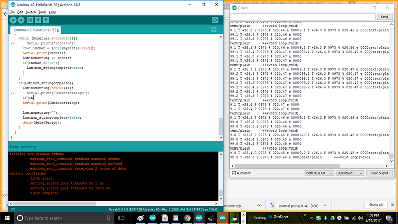
Screenshot of program "luminox-o2-HelloSerial-R2" monitoring O2 sensor. Output is sent at 9600 baud.
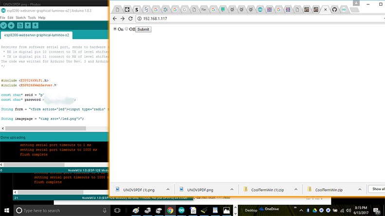
Screenshot of program "esp8266-webserver-graphical-Lumionox-o2" demonstrating graphical user interface connectivity to the solenoid device.
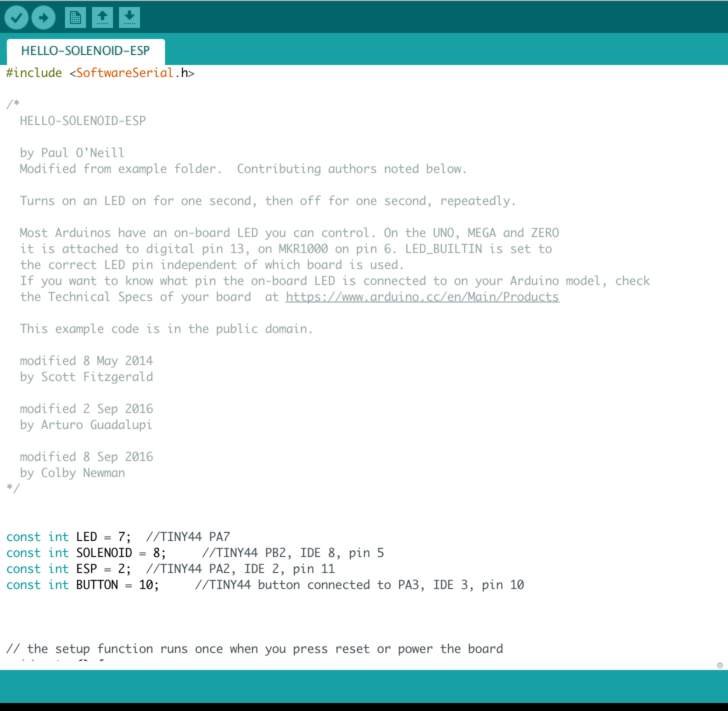
Screenshot of beginning of program "HELLO-SOLENOID-ESP" which communicates with nodeMCU board and operates solenoid valve.
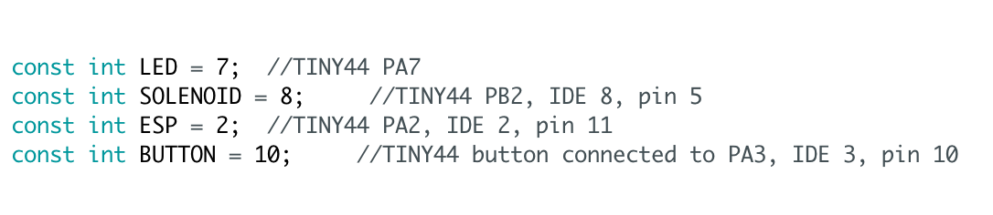
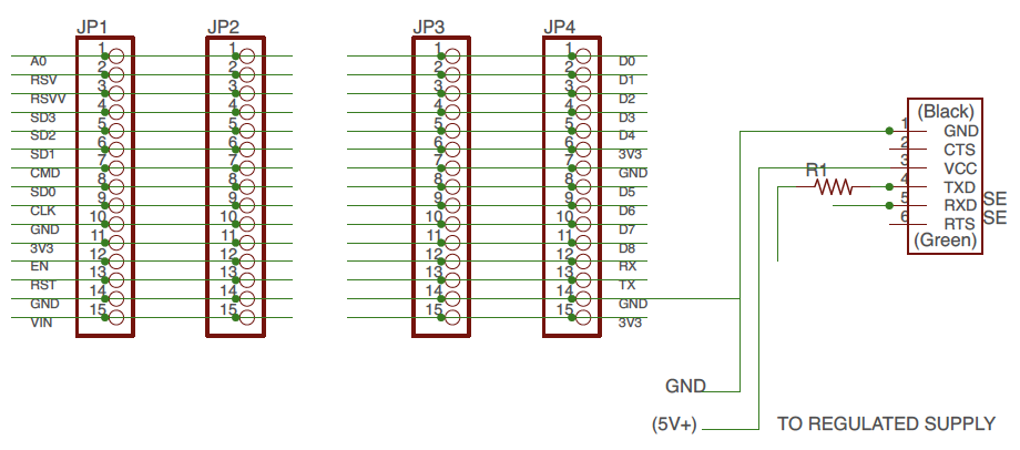
Pinout assignments for the HELLO-SOLENOID board and the hello-nodeMCU board.
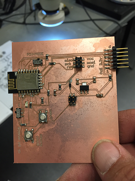
The hello-solenoid board is my 13th revision from "Week 8: Output Devices". The voltage regulator from my earlier revision burned due to being powered from two diffefrent sources. I remidied this on hello-solenoid-r13 by adding two diodes, and it seemed to do the trick. The 100ma MOFSET seems large enough to drive the coil on my solenoid valve. I used a regulated power supply set at 6 volts, and this seemed adequate for both the solenoid valve and the heating circuit of the Luminox-O2 sensor. I also utilized the micro-USB port on tthe ESP8266-12E to supply 3.3V to the serial connections for the Luminox-O2 sensor. I also made a connection from hello-nodeMCU-OX(JP2:D0) to the hello-solenoid-r13(esp-sensor:1). This allows the program executing on the hello-nodeMCU-OX board to control the solenoid valve which is physically connected to the hello-solenoid-r13 board. Port D0 on the nodeMCU also is special in the fact when you press the reset button on the nodeMCU, it causes the solenoid to open. This is useful for testing purposes. This implementation allows the possibility of controlling the solenoid via WIFI. There is also the possibility of controlling the solenoid valve through the monitoring of the Luminox-O2 sensor.
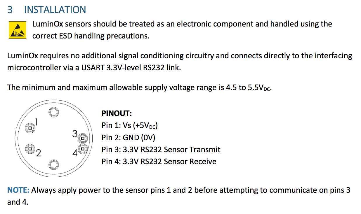
What to do next? On the hardware side, I would make a power supply board with AC adapter. There is a requirement of the Oxygen sensor that the communication lines be disconnected prior to applying power to pins 1 and 2 for heating. If the O2 sensor is powered before or at the same time as the microcontreoller, it seems to hang the microcontroller. Thus, I would provision the power supply board to time-power each of the boards and sensors in sequence. On the software side, I would clearly define application requirements and then proceed in developing code to meet those requirements. Software architecture is really, really important here. Topics such as "big data", "IOT", and "cloud computing" come to mind, and I feel is beyond the scope of Fabacademy. I thought it was important to simply demomstrate the capabilities of the device and leave application development for later.
Now that the hardware is developed, there is huge potential with software development driving the application development. For instance, this device can be installed on a wine storage tank, and wine sold to a customer can be drawn directly from the main storage tank, and as the wine is drawn, inert gas can automatically be added to the tank to prevent oxygen from getting in. This would require two devices. One device to let nitrogen into the tank. A second device to let wine out of the tank. Another example application would be installing on a tank and have the device run every 2 hours for headspace monitoring. If O2 is out of range, trigger an alarm event. The device could be used for purging empty bottles prior to filling with wine. There are a lot of different ways this hardware can be integrated.
I am currently working on combining the ESP8266-012E and the hello-solenoid all on one board. I may want to install a UART and a micro-USB.
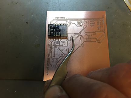
Soldering the ESP8266-12E directly to the board requires using double-stick tape to hold it straight and in place. Even still, very difficult to get the solder to flow. There are Eagle libraries for the modules. However, labels for the pinouts can be all wrong!
Combining the ESP8266 and the solenoid control on one board eliminates many of the headers and wires. This card is not finished yet. I found it extremely difficult to solder the module to the card. I will need to find someone who can demonstrate to me how to use solder paste. I also found the slide switches to be difficult to solder and rather fragile. I may replace them with surface mount male headers and jumpers. Some of the pins on the ESP8266 need to be connected when being flashed. For a one-time operation, I believe a jumper would be more than adequate.
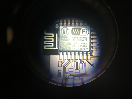
I have learned that the ESP8266 line of modules require a lot of power. They are very economical. They are difficult to flash. You must read the pinouts of the module because each manufacturer can vary what is where. Building a shield for a particular build of ESP can help in the development process. They are easily bricked, so buy more than one. They are cheap enough. Make sure your data lines are at 3.3V. The module does not tolerate 5V AT ALL! There is also an ESP8266Basic programming language I am experimenting with. I will be evaluating how much resource it provides and how well it works with string data.
I would like to improve the case, possibly making it round, and possibly try some XBee modules next. This fall, after harvest, I hope to have a few of these built and actually try in my winery. I think they will be popular with enologists.
Spiral development!
The author is happy to work with other developers on different applications for this device. Please contact paulxoneill at gmail dot com. I have decided to not openly license the product because I have not verified if I have infringed on other work. There is some competitive products you can find on Omega Engineering as well as Davis Instruments. Most of these cost in excess of $5000 and do not work quite the same way as my device.
![]()
